Excellent Machinability
Suitable grades support efficient CNC turning and intricate precision features. Free-cutting C360 is a natural starting point when the application permits a leaded alloy.

Precision Brass Shaft Manufacturing
Precision CNC turning and machining of custom brass shafts for industrial equipment, automation and OEM assemblies. Manufactured to your drawings, material specifications and quality requirements.
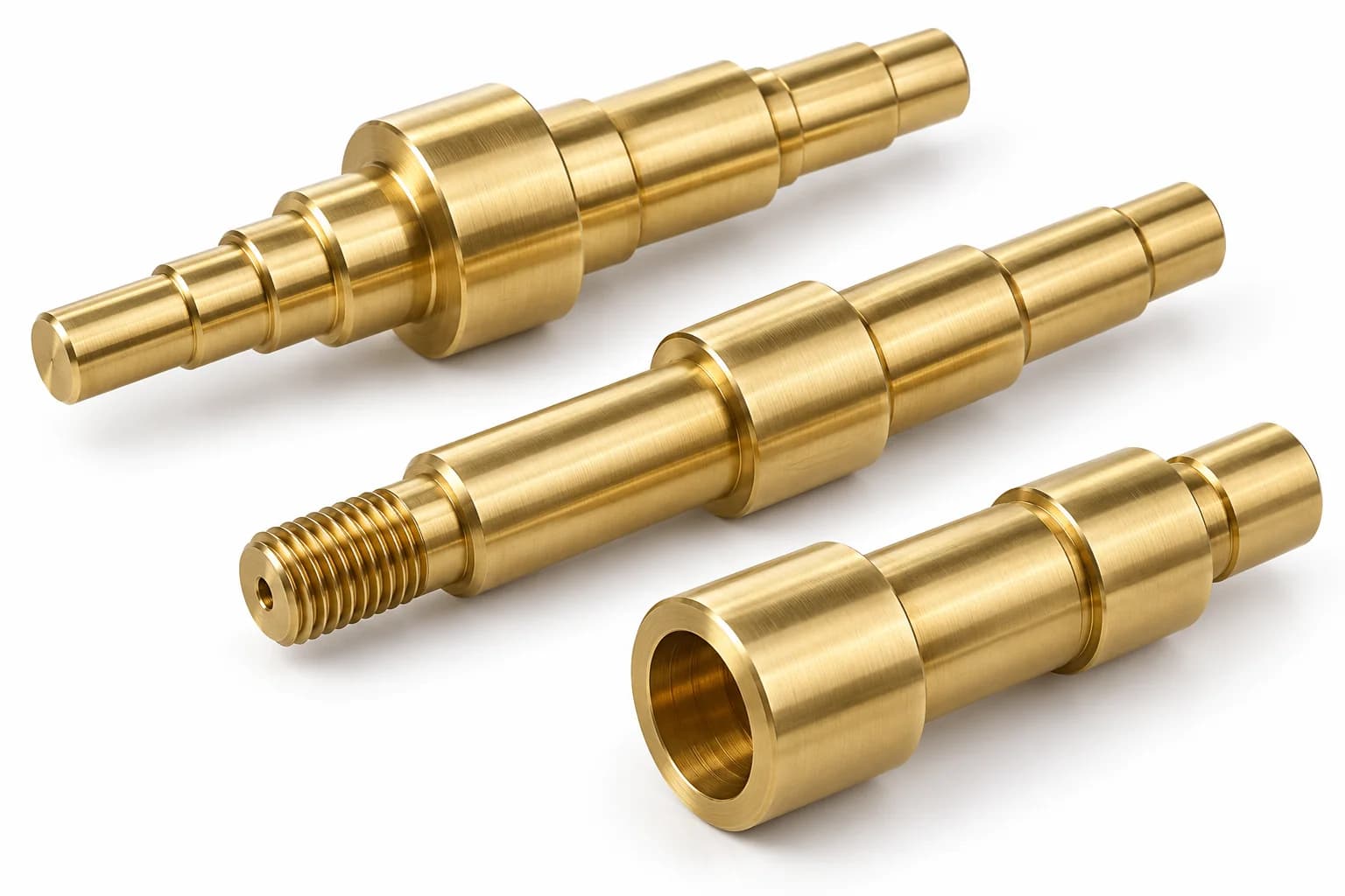
Brass shafts are cylindrical mechanical components manufactured from copper-zinc alloys. They are used in selected rotating, positioning, electrical and mechanical assemblies where machinability, corrosion behavior, conductivity or appearance are important. Custom brass shafts can incorporate stepped diameters, threads, grooves, flats, holes and other drawing-specific features.
Suitable grades support efficient CNC turning and intricate precision features. Free-cutting C360 is a natural starting point when the application permits a leaded alloy.
Useful in many atmospheric and mild service environments, subject to alloy and exposure. Review the actual fluid, temperature and stress conditions rather than assuming universal resistance.
Conductive copper alloys for selected electrical and mechanical applications. Conductivity varies by grade and is not the same as that of pure copper.
Stepped profiles, grooves, threaded ends, flats and drilled features manufactured around the functional drawing, mating components and agreed inspection requirements.
Choose the geometry around the assembly, not just the alloy. These custom brass shaft families link to the relevant existing Topshaft product pages; material suitability and final specifications remain drawing-specific.
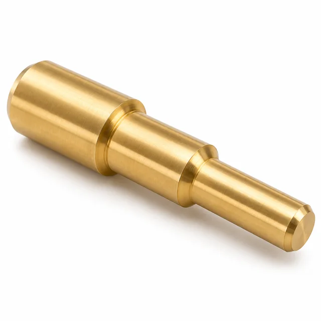
Multiple diameters and shoulders for locating components and defining assembly positions. A brass stepped shaft needs clear journal datums, shoulder relationships and suitable transition radii.
Explore shaft type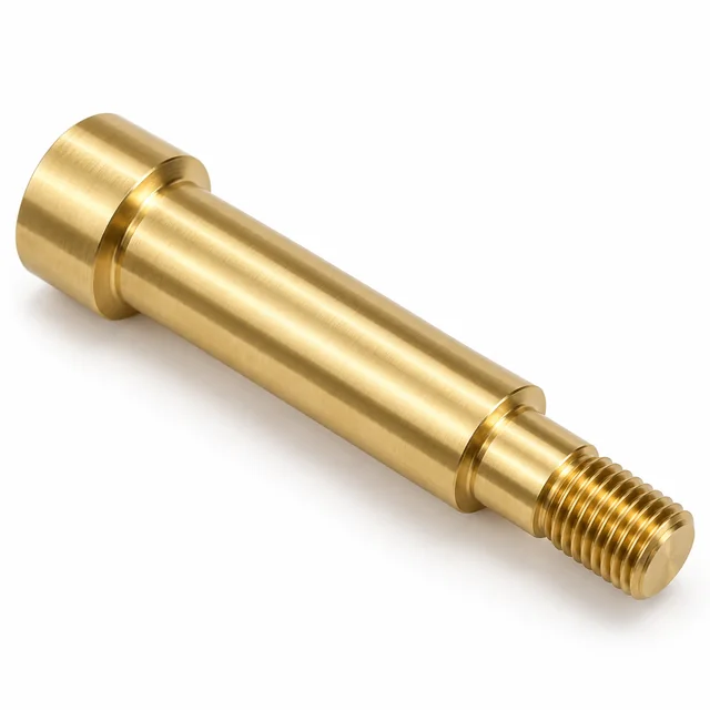
External threads and locating features combined with smooth turned diameters. Specify the thread standard, fit, engagement and any plating allowance for the brass threaded shaft.
Explore shaft type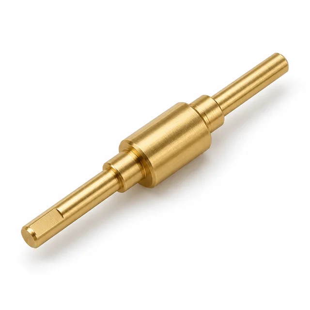
Selected small, low-load mechanisms where the design permits brass. A brass motor shaft requires a specific review of speed, bearing interfaces, stiffness, wear and torque—not a general substitution for steel.
Explore shaft type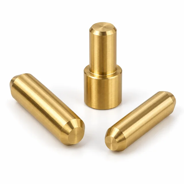
Small locating and pivot components with drawing-defined diameters, lengths and end features. Review mating fits, contact loading, retention and the required surface condition.
Explore custom shaft manufacturing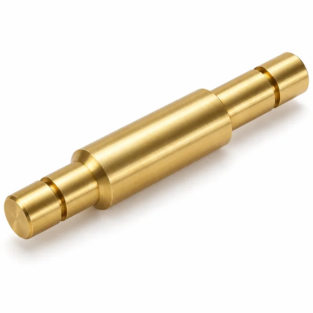
Retaining-ring and positioning grooves integrated into turned shaft profiles. Groove width, depth, edge condition and distance from the functional shoulder are controlled by the drawing.
Explore custom shaft manufacturing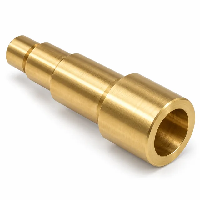
Internal bores and tubular designs for selected assembly or passage requirements. Specify bore depth, wall thickness and the relationship between the bore and external journals.
Explore shaft typeGrade selection connects machining efficiency with the part's mechanical, electrical and environmental requirements. C360 is the primary grade to discuss for free-cutting shaft work; the other grades below are considered upon request, subject to sourcing and technical review.
Swipe horizontally to compare all columns.
| Brass grade | Main characteristics | Recommended shaft applications | Supply review |
|---|---|---|---|
| C360 / C36000 | Free-cutting brass; excellent machinability; contains lead. | CNC-turned shafts, threaded shafts and precision mechanical parts. | Primary inquiry grade; specification, stock form and availability confirmed with the quotation. |
| C260 / C26000 | Higher copper content with good ductility and formability; not an equivalent free-cutting grade to C360. | Special components where formability or specified composition matters. | Upon request; sourcing, supplied condition and machining suitability reviewed. |
| C280 / C28000 | Muntz metal; considered for selected hot-worked and corrosion-related applications. | Application-specific components, subject to product form and suitability. | Upon request; stock form, procurement and application reviewed. |
| C464 / C46400 | Naval brass with tin addition; exposure-specific corrosion assessment remains necessary. | Selected marine-related components after corrosion and strength evaluation. | Upon request; no blanket seawater suitability or stock commitment. |
| C693 / C69300 | Lead-free silicon brass; review the specified composition and manufacturing route. | Projects requiring a lead-free alloy and compatible processing. | Upon request; applicable lead limits, certificates and sourcing confirmed for the project. |
This is a material-selection guide, not a confirmed inventory list. No grade is represented as routinely stocked without a project-specific supply confirmation. Material standard, product form, temper or supplied condition, certificates and any substitution require agreement before the order.
A C360 brass shaft is a practical starting point for efficient CNC turning when leaded brass is permitted. The Copper Development Association uses C36000 as a copper-alloy machinability benchmark with a rating of 100. That comparative rating is not a guaranteed cutting speed, production rate or tolerance for a particular part.
C26000 is a higher-copper brass associated with ductility and formability. It may be selected where those properties or the specified composition matter, but it should not be marketed as an equivalent free-machining grade to C360. Stock form, condition, chip control and the complete route need their own review.
C360 is generally preferred for high-volume precision turning when the material requirement permits it; C260 may be selected for other property requirements. C36000 contains approximately 2.5–3.0% lead under the CDA alloy designation. Identify application-specific restrictions before selection; a plated surface does not establish compliance or remove lead from the underlying alloy.
These references describe alloy properties, not Topshaft stock, equipment ownership or product approval. Confirm the ordered specification and application requirements for each project.
Precision brass shaft manufacturing combines the rotational features, secondary operations and final inspection condition in a coordinated plan. The right process depends on the drawing, alloy, quantity and available equipment—not every shaft needs every operation.
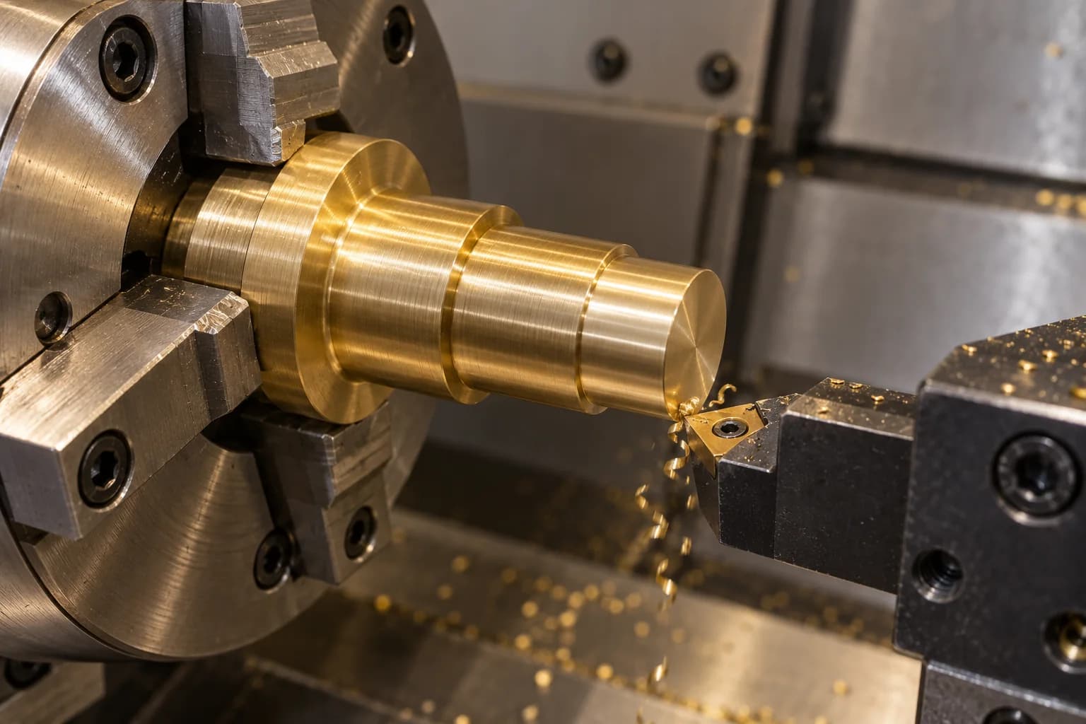
The main brass shaft machining process creates external diameters, shoulders, grooves, chamfers and threaded ends. For a CNC turned brass shaft, the sequence connects the critical journals to a practical rotational datum. Suitable workholding and a planned number of setups help control concentricity; tool condition and in-process checks support repeatability across the agreed batch. Final limits are confirmed against the actual drawing rather than a universal precision claim.
Review CNC turning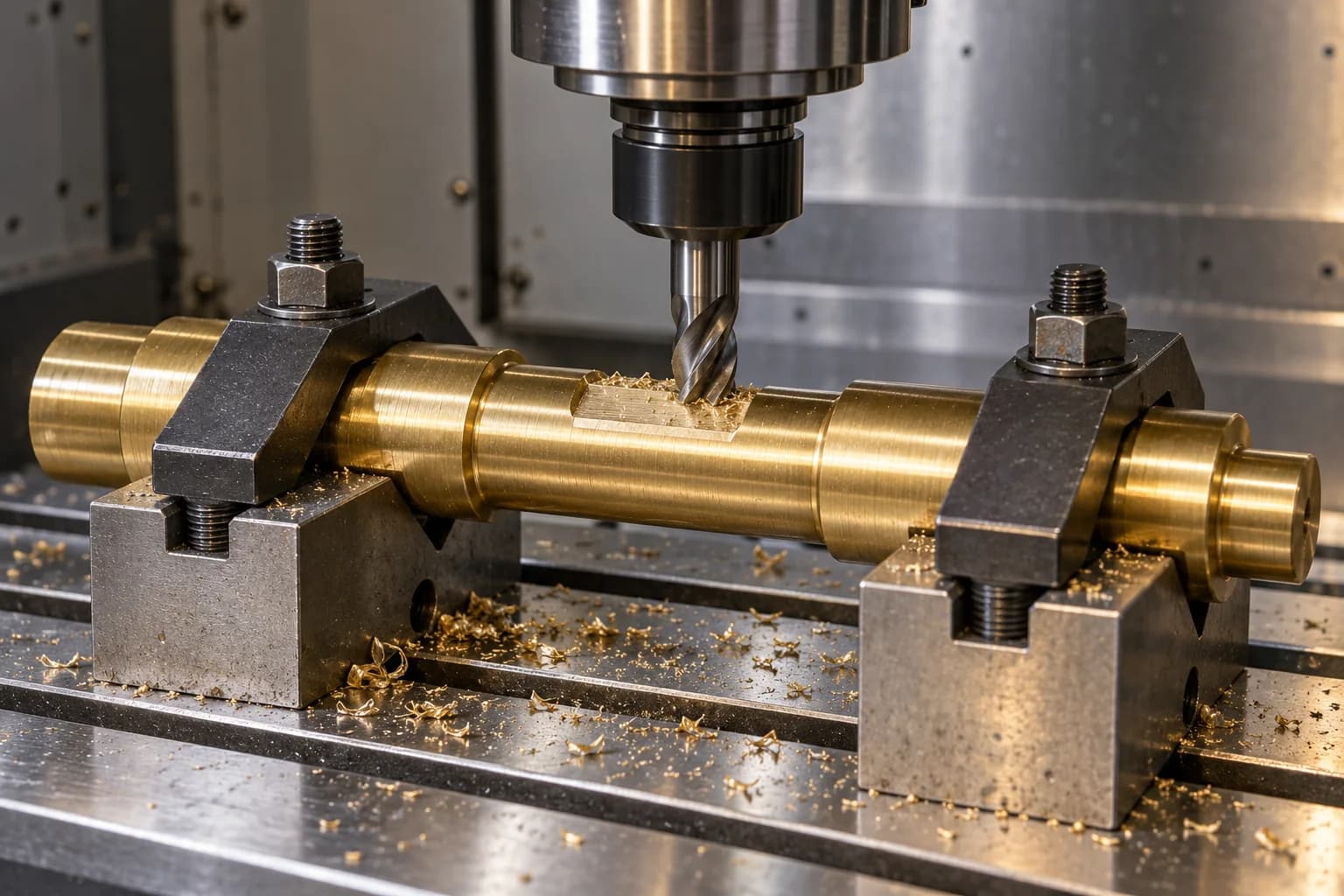
Secondary milling adds flats, slots, keyways, cross holes and other non-rotational features. Their orientation and position need to reference the functional journals or another defined datum. Specify edge breaks and burr-sensitive areas, especially where holes intersect a bore or where a flat locates a mating component. The process plan includes access, support and protection of already finished surfaces.
Review secondary machining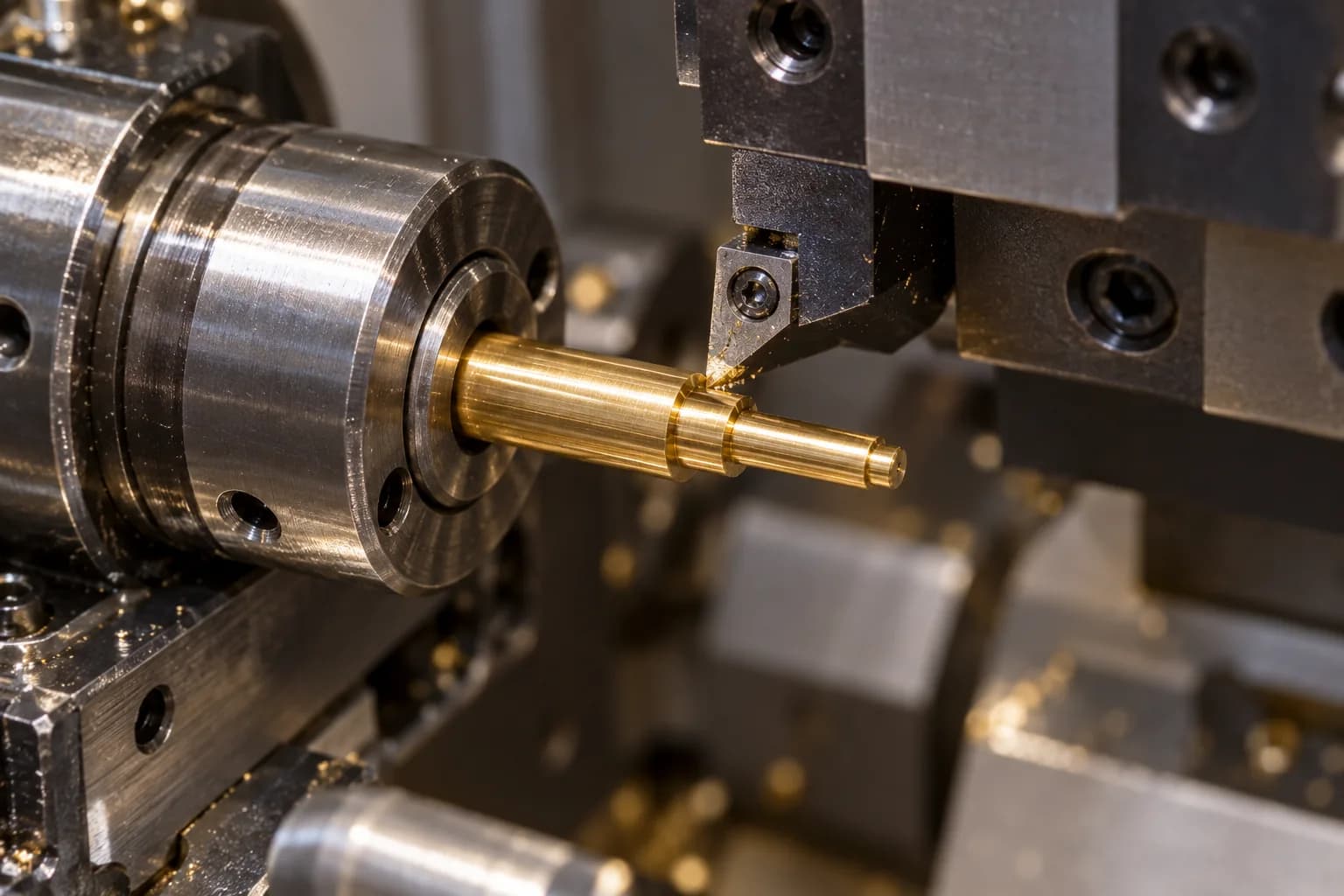
Swiss-type turning can be considered for small-diameter or slender brass designs when the available equipment, guide-bushing arrangement and tooling support the part. It is a project-dependent route, not an assumption that every brass shaft is Swiss-turned. Confirm diameter, slenderness, bar condition, feature access and quantity during review. The quotation must identify an available processing route before production is accepted.
Review custom shaft requirements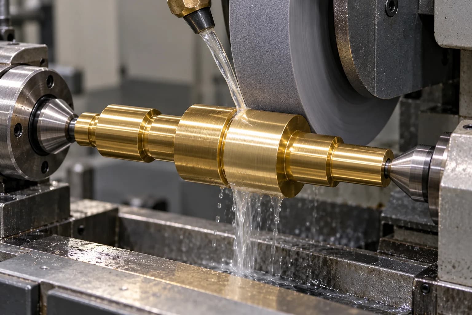
Selected critical diameters or surface-finish requirements may justify grinding or another finishing operation. Many brass shafts can meet their drawing requirements by turning alone; grinding is not automatically necessary. Review the required roughness, final size, stock allowance, support and surface integrity before selecting the route. Plating build-up, when specified, must also be coordinated with the final fit and inspection condition.
Explore precision ground shaftingUse this structured review scope to prepare a quotation. Dimensions, achievable tolerances and supported quantities are confirmed for the actual part; this table is not a blanket capacity or inventory claim.
| Specification | Manufacturing review scope |
|---|---|
| Materials | C360, C260, C280 and other approved brass grades, including C464 or C693 upon request. Ordered specification, stock form, condition and availability confirmed at quotation. |
| Manufacturing methods | CNC turning and CNC milling; Swiss-type turning when supported by the available equipment and tooling. Selected grinding and finishing where required. |
| Shaft diameter | Custom to drawing. Minimum and maximum supported diameters are confirmed after reviewing the blank, largest step, workholding and available manufacturing route. |
| Shaft length | Custom to drawing. Maximum supported length is confirmed with overall length, unsupported span, slenderness, feature access and the proposed process. |
| Dimensional tolerance | Drawing-dependent. Achievable values are quoted by feature, nominal size, geometry, process sequence and final surface condition after engineering review. |
| Concentricity / runout | According to the drawing's datum structure, applicable geometric-tolerance standard and agreed inspection plan. Define the relevant journals and measurement setup. |
| Surface roughness | Specify the required Ra or other roughness parameter, measurement region and final process. A turned, polished or plated surface has different acceptance considerations. |
| Features | Threads, grooves, flats, holes, shoulders, keyways, internal bores and other drawing-defined interfaces, subject to manufacturing review. |
| Surface treatment | As-machined, mechanical polishing and suitable plating options such as nickel or tin, with coating thickness and fit allowance reviewed. |
| Production quantity | Prototype, small-batch and volume-production inquiries are reviewed against procurement, setup, tooling and the available processing route; quantity and schedule confirmed by quote. |
| Inspection | Micrometers, optical measurement, datum-based fixtures, CMM and surface-roughness measurement as appropriate to the specified characteristics. |
| Documentation | Material certificates, inspection reports and First Article Inspection when available and agreed in the order. Confirm traceability, sampling and report scope before production. |
A turned diameter, a ground bearing journal and a long slender shaft can have different process capability and measurement requirements. Submit the critical features and final condition so the manufacturing and inspection route can be reviewed together. Verified minimum and maximum dimensions are supplied with the project quotation.
Select the finish for function, appearance and the operating environment. Confirm the acceptance condition of critical diameters and threads, especially where polishing removes material or a coating adds thickness.
Brass can tarnish naturally. Plating selection depends on the application and does not make every brass grade suitable for every environment. Conventional aluminum-style anodizing is not presented as a standard brass finishing option. Confirm coating requirements and any application-specific material restrictions before production.
Brass is considered where its machining, conductivity or selected corrosion properties support the component's job. These are application starting points, not claims of qualification for every industry or assembly.
Low-load gear and positioning mechanisms where brass properties are suitable. Review the contact surfaces, lubrication, support arrangement and expected wear before selecting the alloy.
Explore gearbox requirementsPositioning shafts, locating elements and mechanical assemblies. Define repeatability-related fits, the direction of loading, retention features and the number of operating cycles.
Explore automation requirementsMiniature shafts and precision-turned mechanical components. Small dimensions still require clear datums, stable support and practical inspection access for the functional features.
Explore machinery requirementsSpecialized conductive and mechanical parts where the chosen brass grade meets the requirement. Evaluate conductivity, temperature, contact design and mechanical loading; brass is not automatically a replacement for copper or a steel motor shaft.
Explore motor assembly requirementsFor a brass shaft vs stainless steel or carbon steel decision, compare the actual alloy and supplied condition with the loads, exposure, conductivity and manufacturing requirement. These broad tendencies do not replace an application-specific design assessment.
Swipe horizontally to compare all columns.
| Factor | Brass | Stainless steel | Carbon steel |
|---|---|---|---|
| Machinability | Excellent for free-cutting grades | Grade-dependent | Grade-dependent |
| Strength | Generally lower | Grade-dependent, often higher | Often higher |
| Corrosion resistance | Good in suitable environments | Often strong, grade-dependent | Usually requires protection |
| Electrical conductivity | Higher than steels; varies by alloy | Low | Low |
| High-torque shafts | Often not preferred | Suitable with correct design | Common choice with suitable design |
| Cosmetic appearance | Distinctive gold tone | Silver metallic | Typically gray metallic |
Choose brass for precision-machined shafts when machinability, conductivity or selected corrosion requirements are important and mechanical loads are moderate. Choose stainless steel or carbon/alloy steel when strength, fatigue resistance, stiffness or heavy-duty power transmission dominates the design.
The dedicated carbon steel material page is not yet available; its existing materials capability page covers quotation requirements.
Inspection starts with the released drawing and the evidence required for acceptance. Agree critical characteristics, datums, sampling and documentation with the manufacturing plan rather than relying on a general statement of precision.
Review the brass grade, ordered specification, supplied condition and stock identification. Request the required material certificate and traceability scope before procurement; appearance alone does not establish alloy identity.
Verify the initial part against the released drawing and agreed inspection plan. Record critical diameters, lengths, shoulders and feature relationships before approving the manufacturing setup for the planned quantity.
Check critical diameters and features at the agreed stages and sampling frequency. Monitor tool wear, burrs and handling damage so the process protects finished locating and mating surfaces.
When specified, inspect the datum-related geometry and surface roughness using a method suited to the drawing. A diameter measurement alone does not demonstrate runout, concentricity or a surface-finish requirement.
Review the final part condition, agreed sampling and required records before shipment. Plated parts require the specified final-condition checks; include material, dimensional and First Article records where ordered and available.
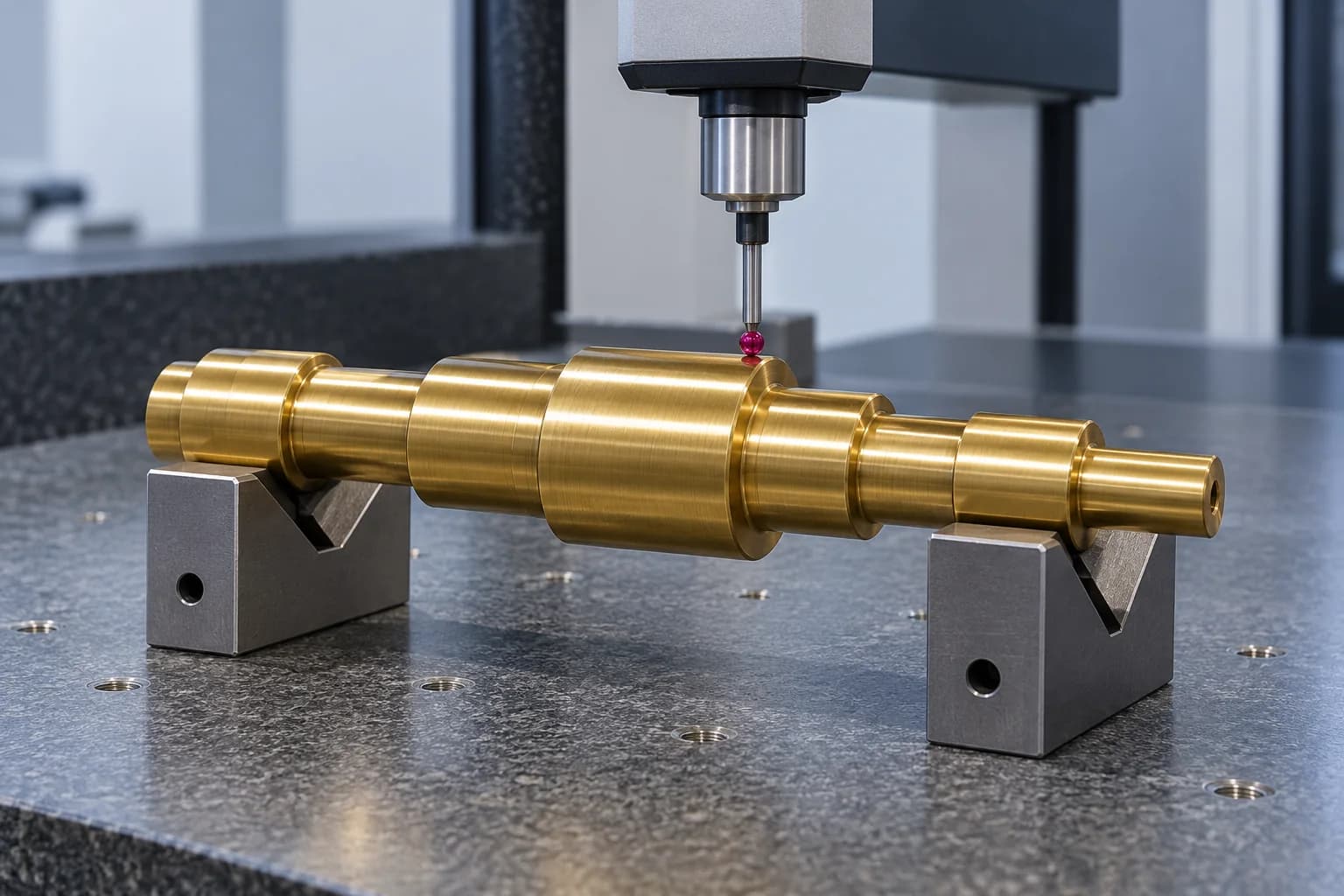
Swipe horizontally to compare all columns.
| Feature | Measurement method | Documentation |
|---|---|---|
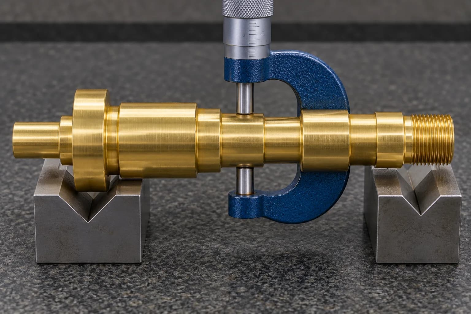
| Outside diameter | Suitable outside micrometer | Dimensional inspection record against drawing limits |
| Datum-based geometric relationships | Appropriate fixture, indicators or CMM, with defined datums | Geometric inspection results and setup reference |
| Threads, grooves and small features | Specified thread gauges and optical measurement as appropriate | Feature inspection record or agreed first-article report |
| Surface roughness | Profilometer with specified parameter and measurement region | Roughness results when required |
| Material specification | Material identification and supplier certificate review | Material certificate and agreed traceability record |
A shaft-focused, drawing-led approach connects material selection with machining, inspection and clear purchasing requirements. The quotation defines the supported manufacturing scope and the records required for your project.
Drawing review connects journals, shoulders, locating surfaces and end features to the assembly instead of treating the part as an undifferentiated brass rod.
A coordinated route considers turned diameters together with milled flats, holes, grooves and other features. Required specialist processing is included in the agreed scope.
Compare brass grades with stainless steel and alloy steel against machinability, conductivity, exposure and mechanical loading before confirming the manufacturing specification.
Functional dimensions, datum relationships and finish requirements are reviewed before machining. Acceptance is tied to the approved drawing and agreed inspection methods.
Prototype, small-batch and repeat-production inquiries are evaluated with procurement, tooling and quantity. The quotation establishes the supported route and delivery requirements.
Clarify material documentation, inspection reports, drawing revisions and shipment requirements with the order. Project-specific records support communication between purchasing, engineering and quality teams.
TOPSHAFT is the precision shaft manufacturing division of Dongguan Tops Precision Manufacture Co., Ltd., operating alongside Topsbest Precision for shaft-focused OEM projects. Learn about Topshaft.
Direct answers to common material-selection, machining and quotation questions.
C360 is a common starting point for general free-machining applications because it supports efficient precision turning. It is not the best choice for every shaft: lead restrictions, strength, corrosion exposure, product form and final processing may require another grade. A C360 brass shaft should be specified with the applicable material standard and condition. Availability and the manufacturing route are confirmed during drawing review.
Yes, when load, speed, wear conditions and the shaft design permit it. Brass can suit selected small rotating mechanisms or positioning assemblies, but it is not a general replacement for steel in heavily loaded drives. Review bearing interfaces, lubrication, stiffness, torque, bending and service cycles. The material decision needs to reflect the complete assembly and required operating life.
Achievable tolerances depend on nominal size, geometry, unsupported length, workholding, process and inspection method. Turning a short journal, finishing a long slender shaft and inspecting a plated diameter involve different constraints. Provide the critical dimensions, datum system and final surface condition so the achievable limits can be quoted after engineering review. No single blanket tolerance is promised for every brass shaft.
C360 is a leaded free-cutting brass commonly selected for machined parts; C260 is a higher-copper brass associated with ductility and formability. C260 should not be described as an equivalent free-machining substitute. C360 contains approximately 2.5–3.0% lead under the CDA alloy designation, so application-specific restrictions must be reviewed. Select the grade for both the required properties and a compatible manufacturing route.
Brass can perform well in suitable atmospheric and mild service environments, but resistance depends on the alloy, medium, temperature and stress condition. Certain environments can cause dezincification or stress-corrosion cracking; ammonia exposure is a particular concern for stressed brass. A naval-brass designation or a plated surface does not establish universal suitability. Describe the actual operating environment and acceptance requirement before selecting the material.
Send Topshaft your 2D drawing or 3D model for a manufacturing feasibility review and quotation. Include grade, standard, quantity, critical tolerances, datum relationships, surface finish and application requirements. File upload supports PDF, STEP, DXF and other listed formats. As a custom brass shaft supplier, Topshaft confirms sourcing, supported operations, inspection records and delivery requirements for the specific project rather than selling generic retail shaft stock.
Brass is usually not the preferred starting material for demanding torque, fatigue or heavily loaded power transmission. Steel, alloy steel or a suitable stainless grade is often more appropriate when strength and stiffness dominate. The final decision still requires the actual torque, bending, stress concentrations, support span and duty cycle. A material change alone cannot compensate for an unsuitable shaft geometry or mating connection.
Yes, subject to the specified coating system, processor availability and project review. Agree the nickel thickness, adhesion, appearance, service environment and final inspection requirements. Coating build-up affects bearing diameters, threads and other close fits, so the drawing must identify the acceptance condition and any masked areas. Plating does not remove the need to check the underlying brass grade or application-specific lead restrictions.
Drawing-Based Manufacturing Review
Submit your engineering drawings and specifications for a manufacturing feasibility review and quotation.
Include the material grade, 2D drawing or 3D model, quantity, critical tolerances, surface finish and application requirements. If a requirement is undecided, describe the operating conditions so the review can identify what still needs clarification.