
Tapered Shaft Interfaces: Geometry, Seating and Inspection
A tapered shaft interface can look simple on a model: a diameter gradually changes along the axis. Yet a supplier needs more than a visually plausible slope. The drawing must establish the intended cone, where its size is defined, how the mating part seats and what evidence demonstrates acceptance. A taper that appears correct can still locate an assembly at the wrong axial position or contact a shoulder before its intended surface seats.
This guide helps OEM procurement and engineering teams prepare a complete requirement before quotation. It concerns the specification and verification of the interface, not a universal assembly recipe. The numerical example is hypothetical geometry, not a recommended fit, load rating or TOPSHAFT capability. Engineering must approve the actual tolerances, mating arrangement, surface requirements and assembly procedure for the application.
1. Explain the Function of the Taper
State whether the taper locates a component, supports a removable tooling interface, participates in torque transfer or serves another purpose. The complete connection can also involve a key, thread, nut, shoulder or other feature. Do not assume that the cone alone provides every function. Identify the mating component and provide its controlled specification when it affects the shaft requirement.
Discuss how the connection is assembled and removed. The approved method can influence access, end features and inspection needs, but it should not be guessed from the taper's appearance. A shallow angle is not sufficient evidence for a particular retention behavior under every material, lubrication and loading condition. Leave service-specific retention and safety assessments with the responsible design authority.
Distinguish a functional seating surface from a lead-in or cosmetic transition. A conical chamfer can resemble part of a taper without sharing its acceptance requirements. Identify where the working surface begins and ends, which adjacent surfaces must clear and which end condition is delivered. This avoids an inspection plan that measures an easy entrance feature while missing the functional interface.
2. Define the Cone Without Contradictory Dimensions
Name the applicable standard interface and edition when a standard connection is intended. For a custom taper, give an approved set of dimensions and tolerances that defines it unambiguously. The ISO 3040:2016 overview describes graphical dimensioning and tolerancing of cones within its scope. Its public overview does not replace the actual drawing rules or the project's approved specification.
Keep the controlling definition clear if the drawing also includes reference information. Nominal end diameters, axial length and angle can become contradictory when separately rounded or independently toleranced. Engineering should decide which requirements govern and how the remaining information is indicated. A supplier should not select the most convenient combination from conflicting dimensions.
Avoid copying an interface name from a catalog without the associated size and variant. Similar names or nearby nominal dimensions do not establish interchangeability. If a mating part is customer-supplied, confirm its drawing revision and actual acceptance basis. Record unresolved questions with feature identifiers so the answer can be linked to the correct interface rather than a general approval of the model.
3. Distinguish Diameter Taper From Half-Angle
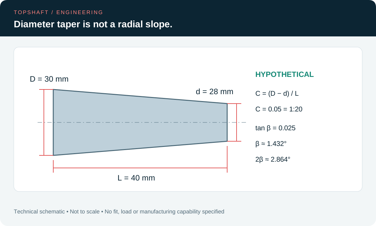
For an ideal circular cone, let D and d be diameters at two sections separated by axial distance L. The diameter taper is C = (D − d) / L. The half-angle β satisfies tan β = (D − d) / (2L), while the included angle is 2β. State clearly which quantity the drawing uses rather than labeling every slope value simply angle.
As a hypothetical example, D = 30 mm, d = 28 mm and L = 40 mm give C = 2/40 = 0.05, or 1:20 as a diameter taper. The radial change is 1 mm over 40 mm, so tan β = 0.025. The half-angle is approximately 1.432 degrees and the included angle approximately 2.864 degrees. These values describe one nominal geometry, not independently approved tolerance limits.
Do not interpret 1:20 as a radial change of one unit in twenty axial units. That would describe a different cone. Likewise, replacing an included-angle value with the same numerical half-angle changes the geometry. Keep enough calculation precision for review and avoid treating rounded explanatory angles as additional binding dimensions. Use the unit conversion guide when documents use different units.
| Requirement | Question to resolve | Evidence to request |
|---|---|---|
| Cone definition | Standard interface or custom geometry? | Approved designation or detail |
| Size location | Where is the reference diameter defined? | Identified plane and dimension |
| Seating | Which surface contacts first and which must clear? | Approved assembly requirement |
| Surface condition | Which finish and treatment apply? | Final-state specification |
| Inspection | Which characteristic does each method evaluate? | Agreed inspection record |
4. Locate the Reference Diameter and Axial Seating
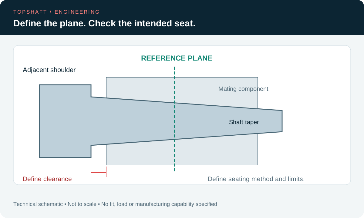
A cone has different diameters at different axial sections. If a reference diameter is used, identify its plane relative to a controlled feature. A size value without its location can leave the axial position ambiguous. A visible physical end is not automatically the intended reference plane, especially when a chamfer, relief or finishing allowance changes that end.
Review how the mating component's axial position is established. It may be evaluated through an approved reference plane, a specified gauge relationship or another defined method. Do not invent a universal gauge stand-off or assume that every taper is accepted by the same seating test. State the method, condition and acceptance values needed for the actual connection.
Check the available clearance to adjacent shoulders and end features. A component can stop against an unintended face while leaving the taper insufficiently seated. Conversely, assuming unlimited axial travel can conflict with the rest of the assembly. Include the relevant stack of interfaces and consult the axial tolerance stack guide when individual dimensions affect the final assembly position.
5. Relate the Taper to the Drawing Datum System
Define the relationship between the tapered interface and the rest of the shaft. Bearing journals, a bore, shoulders or the taper itself may participate in the approved datum system. The manufacturing setup does not decide that system automatically. A convenient between-centers inspection may describe a different reference arrangement from the one required by the product drawing.
Ask how the proposed measurement realizes the specified reference. If rotational variation is checked, identify the reference axis, evaluated region and reported characteristic. A single indicator reading should not be relabeled as proof of every taper requirement. The datum and inspection setup guide helps distinguish the drawing definition from its practical implementation.
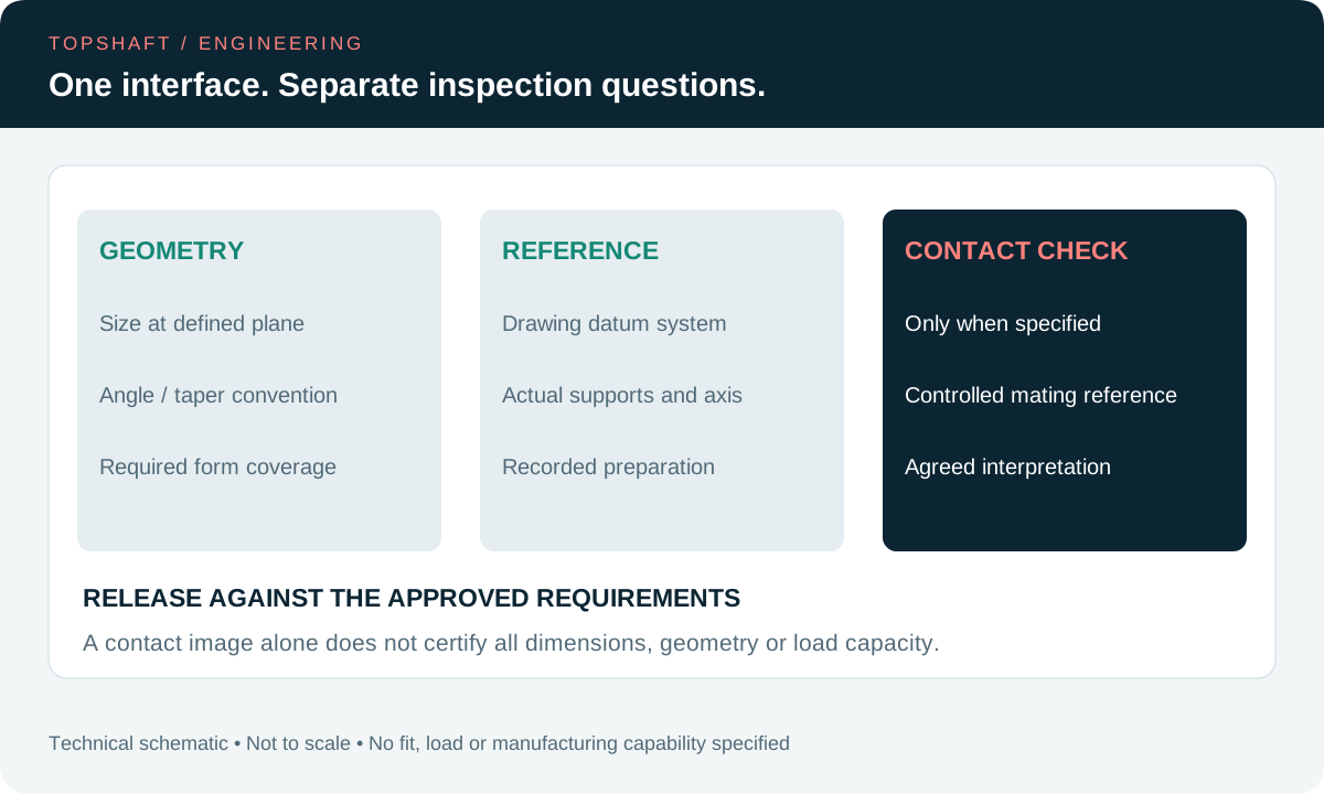
Keep size, angle, form and relation to other features as distinct review questions. Passing one does not automatically prove the others. For example, two section diameters can agree with their nominal values while local surface form still needs assessment under the actual specification. Define the required coverage and method rather than relying on a minimal set of convenient measurements.
6. Specify the Final Surface Condition
State the surface texture requirement for the working taper and distinguish it from neighboring chamfers or reliefs. Specify the parameter and applicable evaluation requirements, not only a vague polished appearance. The surface finish guide discusses why different texture parameters should not be substituted simply because the numbers look similar.
Coordinate the geometry with heat treatment, coatings and final finishing. A requirement before treatment is not automatically a requirement for the delivered part. Identify which dimensions and surface conditions apply after all specified operations. Where a supplier proposes a different sequence, review the resulting final state rather than assuming the nominal taper remains functionally unchanged.
Also agree the condition for assembly or inspection: preservation material, cleaning, dryness or other specified preparation may matter. Do not apply a generic friction assumption or prescribe lubrication from this article. The approved connection procedure must address those conditions. Inspection results should identify relevant preparation so another party does not compare measurements taken under a different condition without knowing it.
7. Agree What a Contact Check Demonstrates
If the customer requests a contact-pattern check, define the mating tool or component, preparation, application procedure and acceptance interpretation. Such a check can provide evidence about contact under the defined conditions. It does not automatically replace dimensional inspection or establish a load capacity. Avoid inventing a universal minimum contact percentage for every shaft taper.
Keep the check compatible with the surface and subsequent operations. Any marking medium or residue must be handled according to the approved cleaning requirements. If a production mating component is used, identify it and control its condition. A worn or damaged reference can change the observation without showing which part caused the difference.
For first articles, review the actual evidence together with the dimensional report. The first article inspection guide can organize the handover. Resolve discrepancies before repeated production, and document any agreed limitations. A photograph of a contact pattern may support review but should not silently become the sole contractual acceptance method.
8. Control Gauges and Measurement Records
Where gauges are used, agree their identification, applicable interface, condition and required control. Do not assume that a tool with the right general name is suitable for the specified size or variant. Define how the result is interpreted and recorded. If the method uses an axial reading, include its reference and units rather than reporting an unexplained number.
Record the part identifier, drawing revision, characteristic, requirement, method and result. Keep contact-check observations separate from numerical dimensions and geometric results. Near a limit, consider the measurement system and agreed decision rule; more displayed decimal places do not by themselves establish better measurement capability. The measurement uncertainty guide addresses that acceptance question separately.
9. Review Rework and Handling
A damaged or nonconforming taper should not be corrected informally by removing material until a mating component appears to fit. Rework can change size at the reference plane, seating position or adjacent clearances. Obtain the required engineering authorization and define the inspections to repeat. Retain the approved disposition with the affected parts and records.
Protect the working surface during storage and shipment without introducing incompatible residue or hiding the identification. Receiving inspection should know what protection to remove and what final state to expect. The shaft packaging guide supports coordination between surface protection, records and access. Packaging is part of preserving an accepted interface, not evidence that the geometry was inspected.
10. Prepare a Complete Tapered-Shaft RFQ
Provide the released drawing and model, interface designation or custom definition, reference plane, datum system and mating-part requirements. Add the final material condition, treatment and surface requirements, assembly preparation, inspection needs, quantity and protection. Ask the supplier to identify ambiguities and proposed alternatives explicitly in the quotation before the order is released.
For custom shafts, share the package through TOPSHAFT contact and confirm the actual manufacturing and inspection approach. This guide does not promise a particular gauge, machine, tolerance or test capability. Use the precision shaft RFQ checklist for the remaining purchasing information and retain approved technical answers with the order.
FAQ
Does 1:20 specify the included angle directly?
No. In the diameter-taper convention used here it means diameter difference divided by axial distance. The half-angle follows from half that diameter change over the same distance. Identify the convention explicitly on the approved drawing.
Is a reference diameter enough without a plane?
Not for an unambiguous axial definition. A cone's diameter varies along its axis. Identify where the diameter applies and how that plane relates to the controlled part geometry.
Can a contact check replace every dimensional inspection?
Not automatically. It answers a contact question under an agreed setup. Define dimensional and geometric verification separately and specify exactly how any contact check contributes to acceptance.
Can a taper be reworked until its mate seats?
Only under the approved disposition. Seating alone does not prove all drawing requirements. Review effects on geometry and axial position, authorize the work and repeat the required inspections.