
Shaft Datum Selection: Bearing Journals, Centers and Repeatable Inspection Setups
A shaft passes inspection at the supplier but appears to fail when the customer rotates it on another fixture. Before changing a tolerance or rejecting the shipment, ask whether both teams established the same reference. Supporting a shaft between centers, resting it in V-blocks and fitting an axis to a measured journal can produce different reference conditions. Those arrangements are not automatically interchangeable simply because the part rotates in each one.
For OEM buyers, datum selection connects assembly function with drawing interpretation and inspection cost. This guide explains what to agree before ordering: which physical features establish the reference, how axial and angular location are controlled, and how another inspector can reproduce the setup. It is an engineering review framework, not a universal GD&T procedure or a statement of TOPSHAFT's equipment or tolerance capability. Apply the standard and edition specified on the released drawing.
1. Start With the Assembly, Not the Easiest Surface
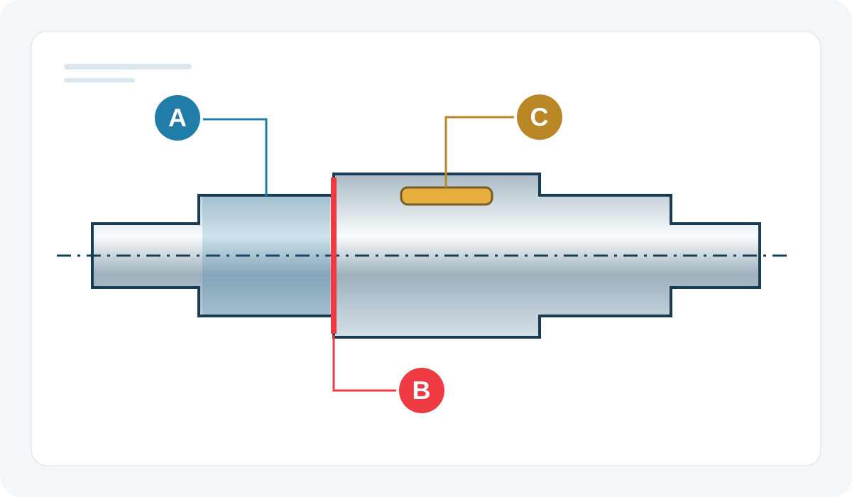
List the surfaces that actually locate the shaft in service. Bearing seats may guide rotation, a shoulder may establish axial seating, and a keyway or other feature may establish angular orientation. A convenient end face or unfinished diameter is not necessarily an appropriate functional reference. Inspectors need to understand why a feature was selected, particularly when a drawing contains several stepped diameters that look equally suitable for support.
Ask what a controlled feature must do relative to its mating parts. A seal journal may need a defined relationship to the bearing-supported axis; a coupling face may need a defined relationship to that axis and its axial stop. Record these relationships before choosing symbols. The bearing journal specification guide provides related fit considerations, while the shaft runout guide addresses the controlled variation. Neither replaces an explicit datum definition.
2. Distinguish a Datum Feature From the Datum
A datum feature is an actual feature of the manufactured part. The datum is the theoretically exact reference established from that feature according to the applicable specification. A real journal has form deviations, surface texture and possibly interrupted areas. Its reference axis therefore cannot be described adequately as simply the visually obvious centerline. The drawing and evaluation rules determine how the real surface establishes the reference used for other measurements.
This distinction matters in procurement language. Asking for a shaft to be concentric to its center does not identify a reproducible reference. Identify the designated feature, its extent and the relevant drawing requirements instead. Do not assume that a software best-fit axis, a physical fixture axis and a design centerline must coincide. They may serve different purposes, and an acceptance plan must explain which one evaluates each requirement.
3. Define Which Journal or Journals Establish the Axis
One journal may establish the primary reference for a particular requirement. Another design may use two separated bearing seats to establish a specified common reference. A drawing may also reference cylindrical features in a sequence. These are different specifications; do not combine them informally into a single axis because that seems convenient for a measuring program. The functional design and the invoked drawing standard must govern the selection.
Identify the usable lengths, excluded reliefs and interrupted surfaces. On a short bearing seat, a small local defect or limited measurement coverage can strongly influence an evaluated axis. On separated seats, their spacing and individual form affect the reference establishment. If the intended reference is unclear, obtain a drawing clarification before quotation approval. A fixture photograph alone is not enough to resolve a disagreement about the underlying requirement.
4. Add Axial Location and Angular Orientation Only Where Needed
An axis alone does not locate every feature completely. In a simplified locating model, a cylindrical axis establishes transverse position and tilt, an appropriate shoulder establishes axial location, and another suitable feature can establish angular orientation. This model explains the functions; it does not prescribe a universal datum sequence, simulator or modifier. Actual constraints depend on the drawing and the geometry of the chosen datum features.
For a shaft with a timed keyway, define which feature controls angular orientation and what surface establishes its axial position. A rotationally symmetric seal surface may not need an angular reference at all. Avoid adding a reference merely to fill three boxes. Each reference should support a functional relationship and a practical inspection strategy. Review shoulder seating and clearance using the shoulder and fillet guide, especially where a radius could prevent intended contact.
5. Treat Center Holes as Specified Features, Not Automatic Datums
Center holes are useful manufacturing and inspection features, but their presence does not make them the acceptance reference for every journal. A shaft finished between centers can still require evaluation relative to its bearing seats. Conversely, a drawing may explicitly require a center-based condition. Inspectors must follow that condition rather than silently substituting the support arrangement that is available on the shop floor.
If center holes are required for an agreed method, specify their delivery condition and protection as appropriate. Damage, contamination or inconsistent seating can change the support condition. Document whether the centers remain accessible after assembly-related operations. Never add or rework center holes on a finished customer part without the necessary approval. A proposed center-based check should be described as a method for a stated characteristic, not proof that all drawing relationships have been verified.
6. Explain What the Fixture Actually Does
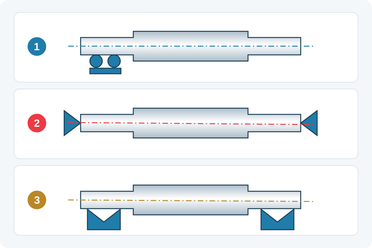
A V-block check can be useful, but contact geometry and shaft form influence the observed indicator variation. A chuck or collet can introduce seating effects or deform a slender section. A between-centers arrangement depends on the center condition and applied support. Rather than declaring one arrangement universally correct, connect the proposed fixture to the datum requirement, the measured characteristic and the expected uncertainty of that complete measurement process.
Describe contact locations, support span, axial restraint, drive method and clamping conditions. Separate supporting the part from establishing the specified reference: a support can prevent sag without defining the datum, provided that the method accounts for its effect. Avoid a fixture that forces the part into an acceptable shape. Where flexibility matters, agree the free-state or restrained condition required by the drawing, and document any assembly-representative restraint explicitly.
7. Control Digital Alignment and Measurement Coverage
For coordinate measurement, record the alignment strategy and the relevant evaluation settings, not just the machine model. State which features establish the reference, the order of reference establishment, the sampled regions and the treatment of excluded areas. A dense collection of points on the wrong surface does not establish the intended reference. Likewise, a report screenshot without the program revision may be insufficient to reproduce the result.
Sampling must address the feature geometry and the inspection objective. Consider axial coverage and circumferential coverage rather than assuming that a few convenient points represent the whole journal. The NPL good practice guide collection includes guidance on CMM measurement strategies and interpreting engineering drawings. Use suitable qualified metrology advice for the actual task; this article does not prescribe a universal point count, fitting algorithm or software setting.
8. Separate Setup Repeatability From Drawing Compliance
Unload and reload a representative part using the proposed procedure, then compare the results for the critical characteristic. If the result changes substantially, investigate seating, cleanliness, contact force, support and alignment before blaming the shaft. Repeatability is valuable evidence about the process, but a highly repeatable measurement can still evaluate the wrong requirement. Agreement between repeated readings does not establish that the chosen datum interpretation is correct.
Where acceptance is close to a tolerance limit, compare the measurement process and its uncertainty with the agreed decision rule. Do not average incompatible setups merely to obtain a passing result. Retain the results and explain any method change. The measurement uncertainty guide discusses near-limit decisions; the datum review should happen before that decision, not become an improvised explanation after a disputed shipment.
9. Put the Reference Strategy Into the RFQ
| RFQ item | What the supplier needs | Why it matters |
|---|---|---|
| Drawing authority | Released revision and invoked standard edition | Prevents mixed interpretations |
| Datum features | Identifiers, usable extent and exclusions | Establishes the intended reference |
| Locating condition | Supports, stops and specified restraint | Makes the setup reproducible |
| Evaluation plan | Characteristic, coverage and report reference | Connects evidence to the requirement |
| Change control | Approval route for method or fixture changes | Prevents silent substitutions |
Ask the supplier to identify assumptions and any inaccessible datum features before accepting the quotation. Separate a preliminary manufacturing proposal from an agreed acceptance procedure. If the design requires a special simulator or a customer fixture, identify responsibility for its design, availability, maintenance and approval. Avoid promising interchangeable results between methods until their suitability has been assessed for the actual part and requirement.
10. Use First-Article Approval to Close the Loop
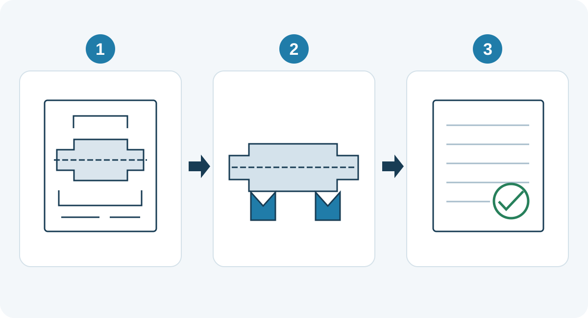
For a first article, connect each critical reported result with the drawing characteristic, datum arrangement, manufacturing condition and approved method. Where useful, include a setup sketch showing contact areas and excluded regions. The sketch should supplement the drawing, not create a competing specification. Record program and fixture identifiers so production and receiving inspection can recognize whether they are using the approved arrangement.
If receiving inspection obtains a different result, preserve the part condition and compare procedures before reworking anything. Confirm part identity, revision, temperature condition, cleanliness, support, reference establishment and evaluation settings. Escalate unresolved interpretation questions to the responsible engineering authority. The first-article guide offers a broader approval checklist; use it to connect the datum review with material, dimensional and production evidence without claiming that one successful sample proves every future part.
11. A Practical Pre-Order Review
- Identify the surfaces that locate the shaft in its assembly and map them to the designated datum features.
- Confirm the applicable drawing standard, edition, reference sequence and any explicit modifiers with engineering.
- Mark usable journal lengths, interruptions, reliefs and surfaces that must not become fixture contacts.
- Agree axial stops, angular orientation, support and any required restraint without inventing additional requirements.
- Verify that the final manufacturing and delivery condition leaves the agreed reference features accessible.
- Record inspection coverage, evaluation settings, fixture identity and the approval route for later changes.
- Plan a repeatability check and agree how a near-limit or disputed result will be reviewed.
Use this list during the technical review rather than attaching it as a blanket purchase specification. Each item needs an application-specific answer or a clear statement that it is not relevant. For a custom shaft enquiry, send the released drawing, mating arrangement, quantity and critical inspection concerns. TOPSHAFT can review the request and confirm the proposed scope during quotation; no equipment, capability or acceptance commitment is implied by this general guide.
FAQ
Is the longest diameter always the best datum feature?
No. Length can help establish an axis, but functional location, accessibility, form and the drawing requirement matter. Do not replace a designated bearing seat with a longer nonfunctional surface without engineering approval.
Can an inspector use centers when the drawing references a journal?
Not automatically. The method must evaluate the specified relationship. A center-based setup may require additional validation or a separate measurement strategy; convenience does not change the drawing reference.
Does low runout prove that the datum strategy is correct?
No. A small reading only describes the result obtained under that setup and procedure. Confirm that the reference, controlled feature, coverage and interpretation match the drawing before accepting the result.
Should every shaft have an angular datum?
No. Angular orientation is relevant when the function requires clocking, such as a timed feature. A purely rotationally symmetric requirement may not need that additional reference. Apply the released drawing, not a generic template.