
Shaft Axial Tolerance Stack-Up: A Practical OEM Drawing Review
Every measured length on a stepped shaft can fall within its drawing limits while an assembled axial gap is still outside the customer's requirement. The problem may be the relationship between dimensions rather than an incorrectly machined part. A shoulder position, two mating widths and a retaining face can accumulate variation that the overall shaft length does not describe. Asking for tighter tolerances everywhere is not the most informative first response.
Start by defining the functional result and the dimensions that actually influence it. This guide explains a simple axial stack review for OEM buyers and engineers. It is not a complete bearing arrangement calculation, a preload specification or a promise that TOPSHAFT supplies tolerance-analysis services. The responsible design authority must approve the model, acceptance limits and any drawing changes. Confirm the manufacturing and inspection scope during quotation.
1. Define the Functional Gap Before the Dimensions
Describe what the axial result means: a free gap, an engagement length, a relative face position or another controlled assembly characteristic. Identify the exact surfaces that bound it and the condition in which it applies. A room-temperature unloaded check may answer a different question from a running assembly under load. State the requirement as an approved range, not merely a preferred nominal value.
Identify who owns the assembly model and who supplies each contributing component. A shaft manufacturer may have no access to the housing, spacer or retaining element data needed for the full chain. Provide the relevant controlled information instead of asking the supplier to infer it. The shaft RFQ checklist helps organize the enquiry, but the customer's functional requirement remains a design input rather than a manufacturing assumption.
2. Draw a Closed, Signed Dimension Chain
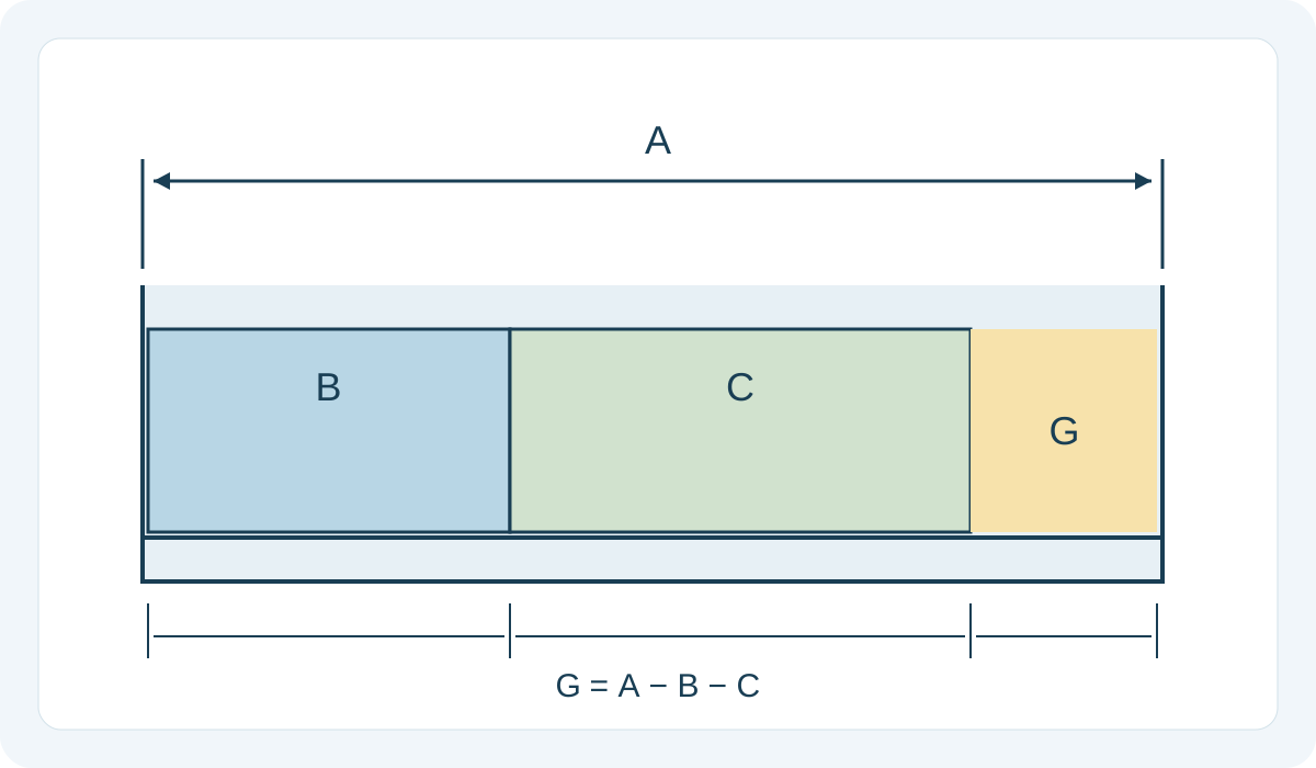
Make a sketch showing the start face, end face and every contributing dimension. Assign a consistent positive direction and write an equation before entering values. For a simple rigid one-dimensional arrangement, a remaining gap may be written as G = A - B - C. Increasing A opens this gap, while increasing B or C closes it. Another assembly can require a different equation.
Include a dimension only once and check that the path genuinely connects the two functional surfaces. Overall length, shoulder spacing and dimensions measured from a common face may not be independent inputs. Do not mix reference dimensions with controlling dimensions without understanding their relationship. Use the shaft datum guide to keep physical references and inspection setups connected to the drawing interpretation.
3. Use Limits Rather Than Nominals Alone
For every contributor, record the nominal, upper and lower limits, units, source drawing and revision. Check whether a general tolerance applies and whether later finishing changes the delivered dimension. A tolerance written as a plus/minus value must be interpreted correctly; its half-range is not its total width. For asymmetric limits, calculate directly from the stated endpoints instead of pretending the tolerance is centered.
Nominal arithmetic shows only the center of a proposed arrangement, not the full possible range. NIST's report on design tolerancing distinguishes worst-case and statistical approaches. For the simple equation here, the minimum gap uses the smallest A and largest B and C; the maximum uses the opposite endpoints. These results apply to the defined model and input limits, not every unmodeled effect in a real assembly.
4. Work Through a Clearly Labeled Example
The following numbers are invented solely to illustrate arithmetic. They are not TOPSHAFT capability claims, recommended shaft dimensions or limits for an actual bearing system. All dimensions are in millimeters, all three contributors are assumed to be the controlling rigid axial lengths, and the equation is G = A - B - C. Geometry, loading, thermal effects and seating behavior are excluded from this numerical example.
| Item | Illustrative value | Meaning in this model |
|---|---|---|
| A | 60.00 ± 0.10 mm | Available axial space |
| B | 25.00 ± 0.05 mm | First occupied width |
| C | 34.60 ± 0.05 mm | Second occupied width |
| G nominal | 0.40 mm | 60.00 - 25.00 - 34.60 |
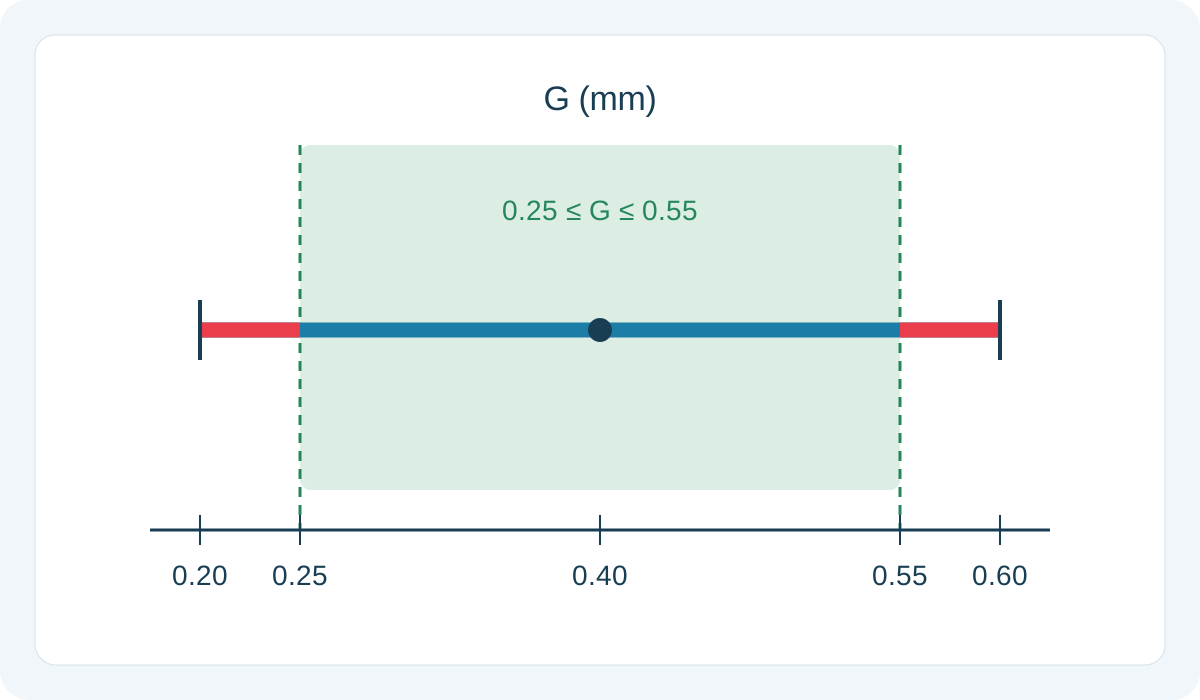
| G limits | 0.20 to 0.60 mm | Endpoint combinations of A, B and C |
The minimum is 59.90 - 25.05 - 34.65 = 0.20 mm. The maximum is 60.10 - 24.95 - 34.55 = 0.60 mm. If an independently specified illustrative requirement were 0.25 to 0.55 mm, the nominal result would look acceptable but the worst-case interval would not fit inside it. That does not prove the real application fails; it shows that this proposed model and tolerance allocation do not establish the illustrative requirement for every allowed combination.
5. Look for the Contributors Before Tightening Everything
In this example, the worst-case half-range is 0.10 + 0.05 + 0.05 = 0.20 mm. A contributes the largest individual half-range, so it is a useful first discussion point. That is not an instruction to tighten A automatically. Ask whether the correct surfaces are in the chain, whether the requirement is justified and whether the dimensioning strategy creates an avoidable accumulation of tolerances.
Review feasibility, inspection access, process sequence and cost before reallocating tolerance. A direct functional distance may communicate the requirement better than several indirectly related lengths, but changing the drawing must not introduce conflicting controls. The shoulder and relief-groove guide helps identify relevant seating features. Do not remove necessary reliefs or change a shoulder merely to simplify a spreadsheet without checking the mating component.
6. Do Not Substitute RSS Without an Approved Basis
A root-sum-square calculation can produce a smaller number than the arithmetic sum, but it is not a new guaranteed limit for every permissible component. Statistical analysis requires an appropriate model of process variation, dependence and the chosen risk criterion. Drawing tolerance limits are not automatically standard deviations. Do not insert plus/minus drawing values into a statistical formula and label the output a demonstrated assembly yield.
The Fritz Scholz report hosted by the University of Washington discusses statistical approaches and their assumptions. Common setups, shared tools, process shifts or selective assembly can matter to the chosen model. If a statistical route is proposed, the design and quality authorities should approve the data, assumptions and acceptance implications. Keep its prediction separate from a worst-case statement and from evidence of actual production performance.
7. Check the Physical Assumptions Behind the Lengths
A scalar axial chain does not automatically cover face orientation, form, burrs, incomplete seating or contact at a fillet. Confirm that the parts actually contact the surfaces represented by the equation. A nominal shoulder position may not describe the assembled position if the mating part bridges a radius or stops against an unintended feature. The model should identify these assumptions rather than hide them inside an unexplained allowance.
Keep geometric controls and assembly requirements explicit. For a particular bearing arrangement, use the bearing manufacturer's instructions and the approved system design for location, clearance and preload. A generic free-gap example cannot specify those requirements. Likewise, do not add an invented adjustment for a retaining ring or threaded fastener; establish the relevant component condition and seating relationship before including it in the chain.
8. Separate Delivery Inspection from Operating Conditions
State the reference condition for the drawing and measurement. Temperature, load and material behavior may change the operating assembly, but those effects require an appropriate separate assessment. A dimensional tolerance is not a general allowance for thermal expansion or elastic movement. If the functional gap is specified at operating conditions, identify who evaluates that condition and how it relates to the delivered-part limits.
Use the inspection temperature guide when defining measurement conditions. Record the relevant mating-part data rather than assuming every component has the same material or temperature. Where the calculation excludes an effect, state the exclusion and its responsible reviewer. This keeps a useful manufacturing discussion from being misrepresented as complete operating validation.
9. Translate the Review into Inspectable Requirements
For each controlled shaft dimension, agree the measurement references, final manufacturing stage, reporting format and decision rule. A calculated gap assembled from separate measurements is not identical to a direct assembly check; each has its own scope and limitations. Link the results to component identities and revisions so the calculation can be reproduced. Never report a theoretical worst-case bound as though it were a measured value on the shipped shaft.
The measurement uncertainty guide explains why near-limit decisions need an agreed basis. Keep numerical rounding and unit conversion consistent, and retain enough calculation detail to reproduce the endpoint arithmetic. If a required assembly check cannot be performed by the manufacturer, state that exclusion in the quotation and identify the party responsible instead of leaving an empty report field that appears to mean acceptance.
When the review is maintained in a spreadsheet, identify the input cells, calculation cells and source documents explicitly. Separate a proposed tolerance from the currently approved one so an exploratory change is not mistaken for a released instruction. Have another reviewer check the sign convention and at least one endpoint calculation independently. A correctly typed formula can still describe the wrong physical path. If a dimension is derived from other controlled dimensions, document that dependency before treating it as another variable. Do not narrow a contractual input range merely because the first few measured parts cluster near the nominal. Actual process data can support a separately approved assessment, but it does not silently rewrite the allowed limits. Finally, record whether any component pairing or selective assembly is assumed; the customer must know if the proposed result depends on matched sets rather than unrestricted interchangeability.
10. Approve the Chain and Control Later Changes
Before ordering, retain the functional requirement, sketch, equation, input limits, source revisions, assumptions and approved review outcome together. Identify unresolved items and the authorization required before production. The drawing revision control guide helps keep the purchase order, manufacturing instructions and inspection records consistent. A spreadsheet revision should not silently change a controlled drawing requirement.
Revisit the stack when a mating width, shoulder, material, process stage or assembly method changes in a way relevant to the model. A previously successful sample does not validate every future revision. For a custom shaft enquiry, send the relevant dimension chain and explain the functional concern separately from the requested machining tolerances. A clear review gives the manufacturer something specific to assess without transferring assembly design responsibility by assumption.
Frequently Asked Questions
Can every part be within tolerance while the assembly gap is wrong?
Yes. Individual limits must be allocated to satisfy the assembly requirement under the chosen model. Nominal fit alone does not establish that relationship.
Does an RSS result guarantee all assemblies will fit?
No. It belongs to a statistical model with stated assumptions and risk criteria. It is not an automatic replacement for endpoint analysis or contractual requirements.
Should every axial dimension use the tightest possible tolerance?
No. Identify the functional chain and review sensitivity, feasibility and inspection before changing limits. Blanket tightening may add cost without resolving an incorrect model.
Does this example define bearing endplay or preload?
No. It is a simplified rigid-length example. Actual bearing arrangements require the relevant manufacturer guidance and an approved application-specific design.