
Shaft Drawings: Inch and Metric Conversion Without Lost Tolerances
A shaft quotation can involve an inch drawing, a millimeter CAD model and an inspection report exported from software configured for another market. Each file may look reasonable on its own. The risk appears when a rounded reference value becomes a manufacturing target, or when a decimal-place tolerance is applied after conversion. A correct multiplication does not by itself establish which document governs acceptance.
For OEM procurement teams, the objective is to preserve the approved geometry and its permitted variation across that document chain. This guide describes a practical review for new orders, legacy shaft transfers and supplier changes. The examples are hypothetical arithmetic, not recommended fits or statements of TOPSHAFT process capability. Resolve conflicting requirements with the design authority before production release.
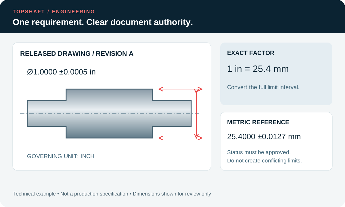
1. Name the Governing Units and Document
Begin with the drawing number, revision, units and contractual document hierarchy. If a drawing and model disagree, the purchase package must say how the conflict is resolved. Do not assume that the newer file date, a native CAD file or the larger displayed number automatically has priority. An explicit answer is cheaper than reconstructing an undocumented interpretation after parts arrive.
Keep primary requirements separate from reference dimensions. A converted value can help a supplier plan work without becoming an additional independent acceptance condition. Clearly identify its status through the approved drawing practice. If both unit systems are intended to be binding, engineering must reconcile the two sets of limits and specify how a disagreement is handled; the supplier should not select the easier one.
Include the original approved file with any working conversion sheet. Give that sheet a revision and an owner, and state whether it is a planning aid or a released requirement. For a broader record of changed requirements, use the drawing revision and change control guide. A conversion worksheet should remain traceable to the source rather than becoming an anonymous screenshot.
2. Convert the Limits, Not Just the Nominal
The international inch is exactly 25.4 millimeters, as explained by NIST's length reference. That exact factor does not make a rounded display exact. Work from the original stated limits, retain enough numerical precision during calculation and review the final presentation. These are different tasks from deciding which tolerances are appropriate for the application.
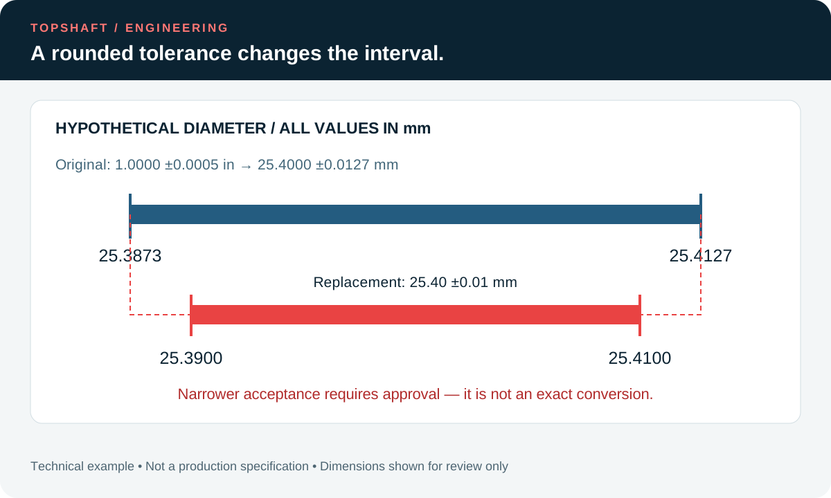
Consider a hypothetical diameter of 1.0000 ±0.0005 in. Its limits are 0.9995 and 1.0005 in. Multiplication by 25.4 gives 25.3873 and 25.4127 mm, with a nominal of 25.4000 mm and a half-width of 0.0127 mm. The arithmetic preserves the original interval; no bearing fit, surface texture or measurement method follows from those numbers alone.
Rewriting that requirement as 25.40 ±0.01 mm instead creates limits of 25.39 and 25.41 mm. That interval is narrower than the original, so some originally permitted sizes are excluded. Conversely, 25.4 ±0.02 mm creates a wider interval. Neither rewrite is an exact conversion. If the drawing must change, obtain approval for the resulting limits and document the engineering reason.
3. Review Decimal Places and General Tolerances
Some drawings assign general tolerances according to the number of displayed decimal places. Changing 1.000 to 25.4 can therefore change the apparent tolerance category if a reader applies the title block mechanically. The number of digits used to display a converted value does not independently authorize that change. Review explicit tolerances, general notes and any invoked standard together.
Prepare a characteristic-by-characteristic reconciliation for important journals, shoulder locations, grooves and mating features. Record which requirements are directly toleranced and which inherit general tolerances. Resolve missing or contradictory instructions before the quotation is finalized. Do not automatically attach the metric title block of a conversion template to a legacy inch drawing and assume functional equivalence.
| Review item | Conversion risk | Required resolution |
|---|---|---|
| Journal diameter | Nominal converted, tolerance omitted | Preserve approved upper and lower limits |
| Shoulder location | Decimal-place rule changes | Identify the applicable general tolerance |
| Reference dimension | Planning value becomes binding | Mark its approved reference status |
| Thread callout | Diameter treated as full designation | Retain standard, size, pitch and class |
| Inspection output | Rounded result hides proximity to a limit | Agree units, reporting precision and decision rule |
4. Keep Threads and Fits as Complete Designations
A thread is not defined by a converted major diameter. Its standard, nominal size, pitch or threads per inch, form, tolerance class, handedness and engagement requirements remain relevant. A nearby metric nominal size is not automatically interchangeable with an inch thread. Do not replace the callout simply because a calculator produces a familiar diameter.
Likewise, converting a shaft dimension does not select a new fit class. The mating bore, assembly method and operating conditions still belong to the approved design. If a supplier proposes a standard metric bearing or coupling as an alternative, treat that as a design change with an interface review. The shaft thread specification guide explains the additional thread information to keep in the RFQ.
Check purchased mating parts by their full identifiers and specifications. A catalog title may use a rounded size while the detailed drawing supplies actual limits. Confirm which dimensions govern the shaft interface, including locating shoulders and reliefs. Record questions with a feature identifier so the customer's engineer can answer the specific uncertainty rather than approving a vague statement that all units were converted.
5. Check Model Scale Before Programming
An imported model should be checked against known dimensions from the governing drawing. Compare an overall length and at least one critical diameter rather than relying solely on a software import message. Record the import units, the resulting measured values and the file revision. A visually plausible shaft is not proof that its scale is correct.
The design can also be wrong at only one interface if geometry was copied from a differently configured library. Check feature relationships, not only the bounding box. If the model is deliberately simplified, identify which omitted details are controlled by the drawing. Do not regenerate missing threads, chamfers or reliefs from general modeling defaults and treat them as customer-approved geometry.
When machining programs, setup sheets or checking fixtures are derived from a converted model, their approval trail should point back to the same released source. A later model replacement should trigger a review of affected downstream documents. The appropriate review scope depends on the actual change; conversion alone does not justify skipping the first article inspection review.
6. Treat Other Quantities Separately
Not every number on a shaft drawing is a length in the main drawing units. Surface texture, angles, hardness, coating thickness and torque may use separately stated units or defined scales. Read the symbol, parameter and note before applying a factor. In particular, hardness scales are not ordinary linear length units and should not be converted with a dimensional multiplier.
For surface texture, preserve the specified parameter and evaluation conditions as well as its units. A value for Ra cannot be substituted for Rz merely by changing the unit label. For a coating, determine whether the requirement describes thickness per surface or the final size of the coated part. The surface finish guide provides a separate checklist for these distinctions.
Angle values are not multiplied by 25.4, while a linear positional tolerance may be. Thread pitch expressed as distance per turn and threads per inch require different arithmetic. These examples show why a global find-and-replace operation is unsafe. Classify each requirement first, then verify the conversion against its meaning and the approved standard or customer instruction.
7. Agree How Inspection Results Will Be Reported
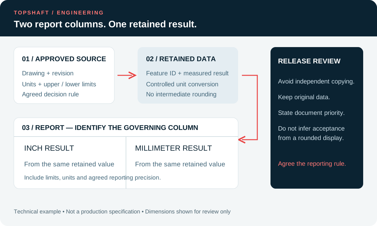
The report should identify the drawing revision, feature number, nominal or specified limits, measured result and unit. If a measurement system works internally in another unit, keep a controlled conversion process rather than copying a rounded display into a second spreadsheet. The reported precision should be sufficient for the agreed acceptance process without implying more measurement capability than the system provides.
Do not infer conformance from a display that merely rounds to a limit. For example, a displayed 25.41 mm does not reveal whether the underlying result was 25.409 or 25.414 mm. The appropriate decision depends on the governing limits, retained data, measurement uncertainty and agreed decision rule. The measurement uncertainty and acceptance guide discusses that separate decision.
If the customer requires both inch and metric report columns, identify which column governs and derive both from the same retained result. Do not perform two independent manual transcriptions. Include enough context for receiving inspection to reproduce the comparison, and agree the reporting convention before production rather than changing the number of digits after a disputed measurement.
8. Use a Conversion Review at Supplier Handover
Assign one owner to prepare the conversion and another competent reviewer to check critical characteristics. Review the original limits, arithmetic, output rounding, feature identity and status of reference values. The review should address functional interfaces and documentary authority, not simply confirm that every cell contains a formula. Keep questions open until the responsible design authority answers them.
For repeat work, retain the approved conversion record with the quotation and inspection plan. Do not silently reuse a spreadsheet from a similar shaft; its general tolerances, thread system or source revision may differ. Recheck links to CAD models and purchased part specifications when the order changes. A familiar part name is not a reliable revision identifier.
9. Prepare a Clear RFQ Package
Send the approved drawing and model, document priority, governing units, explicit limits and applicable general tolerances. Add the quantity, material condition, finish requirements and requested inspection output. Identify any converted reference sheet separately. Ask the supplier to list unresolved unit or interpretation issues in the quotation so the commercial scope and technical scope can be closed together.
For custom shafts, share this package through TOPSHAFT contact and confirm the available manufacturing and inspection approach for the actual geometry. This article does not establish a universal achievable tolerance, equipment list or acceptance service. The precision shaft RFQ checklist helps assemble the remaining procurement information without replacing engineering approval.
10. Unit Reference and Release Check
NIST provides the exact inch relationship in its SI length reference and discusses factors and rounding in its unit conversion resource. Those sources support unit arithmetic, not a particular shaft fit or a contractual tolerance hierarchy. The workflow and examples here are practical review suggestions that must be adapted to the approved project requirements.
Before release, verify that the drawing, conversion sheet, model, purchase order and inspection template all identify compatible revisions and the same governing limits. Check a sample calculation in both directions without rounding intermediate values. Archive the approval and remove superseded working copies from production use. That closes the document chain while leaving any intentional design change visible and reviewable.
FAQ
Does 1 inch always equal 25.4 millimeters?
For the international inch used here, yes: the relationship is exact. A printed converted value may nevertheless be rounded. Distinguish the exact factor from the precision of the displayed requirement and from the uncertainty of a physical measurement.
Can we round the metric tolerance to a convenient value?
Only if the responsible authority approves the resulting requirement. Compare the new upper and lower limits with the original interval. A convenient display can narrow or widen acceptance and should not be treated as an unchanged conversion.
Should both units appear in the inspection report?
They can when useful or required, but establish one governing basis and an agreed reporting convention. Generate both values from the same retained result, identify units clearly and avoid repeated rounding or independent transcription.
Does converting a thread diameter create a metric thread?
No. Preserve the complete thread designation and mating requirements. Substituting a metric thread is an interface change that needs engineering review, including pitch, form, class and the mating component.