
Shaft Center Holes: Drawing Requirements, Condition and Inspection
A small recess at the end of a shaft can influence several operations without being part of the assembled product's working interface. It may support turning, grinding, inspection or later maintenance. Buyers often focus on bearing journals and overlook whether the center holes must remain, may remain or must be removed. That missing instruction can become a disagreement when finished parts arrive with unexpected end features.
This guide helps OEM engineers and procurement teams define center-hole requirements before quotation or supplier transfer. It separates the delivered feature, the manufacturing support and the inspection setup. The diagrams are explanatory, not dimensioned production drawings. Hole size, permitted load, contact pressure and machine settings require a project-specific assessment; nothing here establishes TOPSHAFT equipment, achievable accuracy or a universal process capability.
1. Decide Whether the Finished Shaft Keeps the Holes
State the final condition at each end independently. A shaft can need a retained center hole at one end while the other end has a threaded interface, a sealed face or a finished appearance requirement. An instruction for both ends should be explicit rather than inferred from a symmetric model. Identify the relevant end with a drawing view or feature number.
If holes are optional manufacturing features, define the boundary of that permission. A supplier's convenient support feature should not interrupt a specified sealing face, reduce an approved interface or conflict with an assembly drawing. If no holes are allowed on the delivered part, discuss removal and subsequent finishing in the quotation. Do not assume that facing them away leaves all other dimensions unchanged.
For retained holes, explain their future use. A hole needed only for current machining may require a different acceptance package from one reserved for customer inspection or service regrinding. Agree the final surface condition, protection and records accordingly. Changing a retention instruction after production planning can affect stock allowance and sequencing, so route it through drawing revision control.
2. Specify a Form and Size Through an Approved Definition
Do not rely on a note that simply says center drill. Name the governing standard and edition, the selected form and size, or provide a complete custom detail. The DIN Media listing for DIN 332-1 identifies that document as covering 60-degree center holes of types R, A, B and C. Its public listing is not a substitute for the actual dimensional requirements.
A designation must be read with the applicable standard or customer drawing. A familiar angle does not establish the full geometry, and a drill catalog reference does not automatically define the finished part. SPPW's centering application overview distinguishes center-drill forms and spotting tools. This supports checking the intended tool and hole function separately, not treating every conical recess as interchangeable.
When a custom shape is necessary, define the contact region, entrance, clearance and depth information needed to interpret it. Avoid supplying unrelated dimensions that contradict a standard callout. Have the design authority resolve the governing definition before the supplier chooses tooling. Do not select a standard size from shaft diameter alone without considering the actual support arrangement and approved requirements.
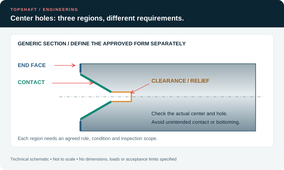
3. Separate Contact, Clearance and End-Face Requirements
The surface intended to seat against a center is different from the small relief region beyond it and from the surrounding end face. Identify which region has a controlled finish, geometry or damage criterion. A drawing that gives only an opening diameter can leave the working contact surface insufficiently defined even when that diameter is easy to measure.
Check the proposed support against the actual hole. Its intended contact should not be defeated by bottoming, interference at another region or contamination between surfaces. The diagram shows the concept, not a permissible contact pattern or a setup approval. The supplier must confirm compatibility with its selected center and operating conditions; the buyer should not prescribe an arbitrary axial force from a generic example.
Keep end-face requirements visible in the review. A retained recess can share limited space with a thread, marking, lubrication feature or removal allowance. Review the complete end configuration rather than approving each feature in isolation. If a center hole intersects another bore, treat the intersection and cleaning access as explicit issues instead of assuming a conventional blind-hole detail still applies.
| Drawing question | Risk if left open | Information to agree |
|---|---|---|
| Must the hole remain? | Unexpected feature on delivered end | Final condition at each end |
| Which form and size apply? | Tool choice substitutes for part definition | Approved standard designation or detail |
| Which surface supports the center? | Unintended contact or interference | Contact and clearance regions |
| What axis governs inspection? | Setup result mistaken for drawing compliance | Datum system and measurement arrangement |
| May the hole be corrected? | Rework changes approved geometry | Authorization and required reinspection |
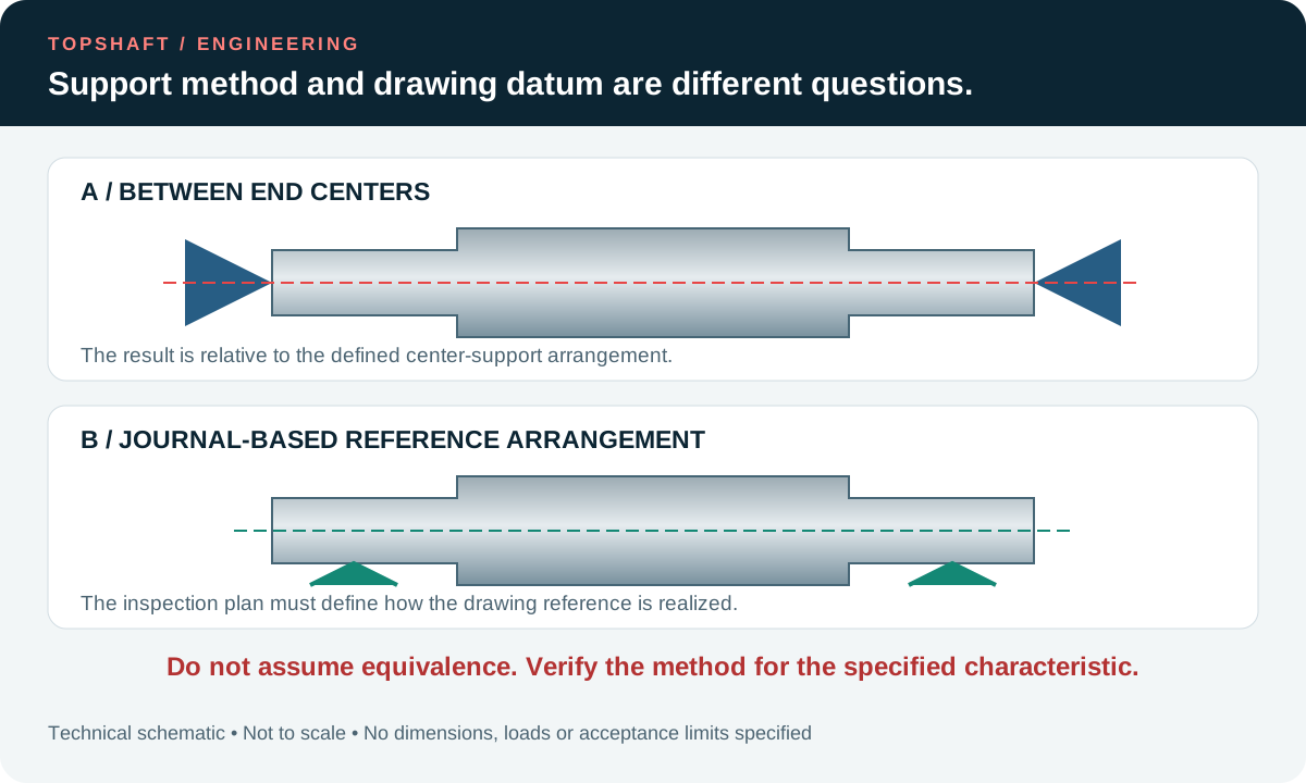
4. Keep Manufacturing Support Separate From the Datum System
Machining between centers does not automatically make the center holes the drawing datums. The product may be functionally located by bearing journals, a bore, shoulders or another defined datum system. Explain the relationship between that system and any proposed between-centers measurement. A setup that is convenient and repeatable can still answer a different question from the drawing requirement.
For example, measuring a journal while supporting the shaft on its end holes describes variation relative to that support arrangement. It should not be relabeled as compliance to a journal-based datum axis without demonstrating that the method evaluates the specified characteristic appropriately. The datum selection and inspection setup guide explains why the datum and its physical realization need to be reviewed together.
If the customer explicitly defines the center features as part of the datum arrangement, document how they are contacted and how the relevant axis is established. Include required preparation and any setup restrictions in the inspection plan. Resolve disagreements during the method review rather than letting the supplier and receiving inspector use different supports while reporting the same characteristic name.
5. Plan the Condition After Heat Treatment and Finishing
Ask when the holes are produced and what later operations can alter them. Heat treatment, surface treatment, cleaning and handling may change the condition available for subsequent support. The process plan should address the required final state rather than merely record that a center-drilling operation occurred earlier. Do not assume every hole will be finished again after treatment.
Where a supplier proposes cleaning, restoring or finishing the contact region, agree the permitted scope. Removing material may alter depth, opening or the relationship to adjacent features. A process recommendation is not permission to change a released requirement. Link the discussion to the heat treatment specification guide when sequence and final inspection condition affect the order.
Also consider coatings and preservation materials. A temporary protective film is not necessarily intended to remain during measurement, while a specified permanent surface treatment must not be removed casually. State the condition for checking and shipment. If different stages use different conditions, make those stages identifiable in the records so results are not compared without their preparation context.
6. Define Cleanliness and Damage Acceptance
Debris in a support recess is not simply an appearance issue when the feature is later contacted. Define cleaning expectations and the condition in which the part is presented for setup. Avoid a vague requirement such as perfectly clean without a method or acceptance basis. Where relevant, use the shaft cleanliness guide to agree accessible regions and verification scope.
Address burrs, dents, corrosion and other indications in the actual contact region separately from allowable marks elsewhere. A visual check can identify visible conditions but does not prove every geometric or material requirement. Specify the observation conditions and escalation path for unclear findings. Do not turn an unexplained shiny patch into an automatic pass or fail criterion after delivery.
If contact marking is proposed to examine seating, agree the method and interpretation before use. It is supporting evidence for the defined question, not a universal substitute for dimensional verification. Any cleaning agent or marking residue must be compatible with later operations and removed as required. Confirm the available method with the supplier rather than assuming it is included in every inspection service.
7. Make the Inspection Record Reproducible
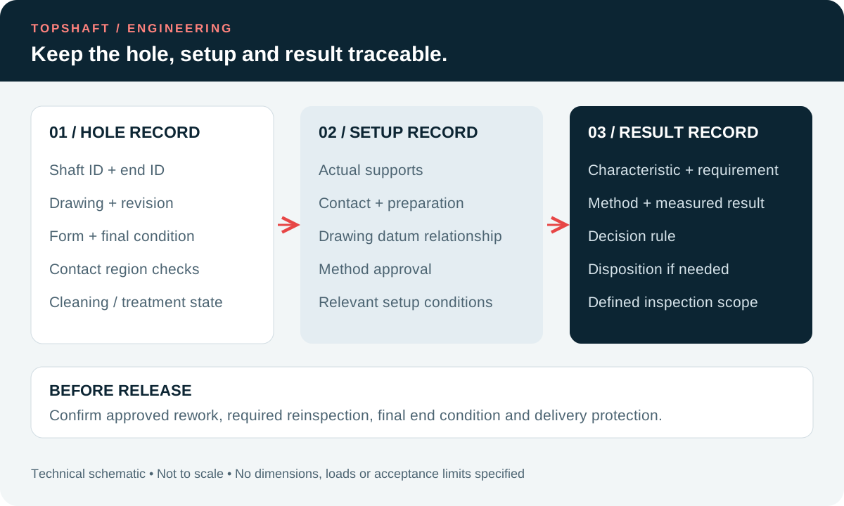
Record the shaft identifier, drawing revision, hole or end identifier, specified requirement, method and result. For between-centers checks, identify the support arrangement and relevant setup conditions sufficiently for review. A result without its reference arrangement can be misleading when another party repeats the measurement differently. Keep the method tied to the characteristic rather than using one generic setup note for every feature.
Separate inspection of the holes themselves from inspection of journals or other surfaces while supported by them. These are related tasks but they are not identical. A journal result does not automatically certify all center-hole requirements, and a conforming center hole does not prove the rest of the shaft conforms. Define what is checked, what is reported and what remains outside the agreed scope.
For first articles, review representative setup records and clarify discrepancies before repeating production. The first article inspection guide can structure that handover. If results depend strongly on setup or are close to a limit, consider the measurement system and agreed decision rule. Adding decimal places to a report does not resolve an unsuitable reference arrangement.
8. Control Rework and Future Reuse
Do not allow a damaged center hole to be corrected informally merely because the shaft still fits a machine. Assess the applicable hole requirements, adjacent geometry and intended later use. Obtain authorization before material removal changes an approved feature, and define which inspections must be repeated. Keep the disposition associated with the affected parts and revision.
For service regrinding, retained holes can be useful only if their suitability is confirmed at that time. Their presence is not a guarantee of preserved alignment or condition after storage and operation. A future service procedure must evaluate the actual shaft and support strategy. Avoid promising unlimited reuse or a particular recovery accuracy from a drawing note alone.
9. Include Protection in the Delivery Package
Agree how retained holes and end faces are protected without contaminating critical surfaces or obstructing customer handling. Identify any plugs, protective material or preparation that must be removed before measurement or assembly. The appropriate method depends on the complete part and transport conditions; a standard packaging photo does not define the agreed requirement.
Receiving inspection should know whether the holes are retained functional support features, permitted process remnants or prohibited on the final part. Include that distinction with the relevant records and packaging instructions. The precision shaft packaging guide helps coordinate surface protection with identification and inspection access, rather than leaving the end condition to an unpacking assumption.
10. Send a Complete Center-Hole RFQ
Provide the released drawing and model, final condition for each end, approved geometry definition, contact-surface requirements and intended future use. Add the datum system, proposed inspection needs, material condition, treatment sequence, quantity and delivery protection. Ask the supplier to identify unresolved requirements and any proposed alternatives explicitly in the quotation.
For custom shafts, share the package through TOPSHAFT contact and confirm the actual manufacturing and inspection approach before ordering. This review should clarify scope, not create unsupported capability claims. Use the precision shaft RFQ checklist for the remaining procurement details and retain the approved technical answers with the order.
FAQ
Must every precision shaft have center holes?
No. The design, permitted final geometry and selected manufacturing route determine whether they are appropriate. Specify whether they must remain, may remain or must be absent; do not treat them as an automatic feature of every precision shaft.
Does a 60-degree callout fully define the hole?
No. It does not establish the complete form, size, clearance or delivered condition. Use an approved standard designation or a complete drawing detail, and check compatibility with the intended support.
Is between-centers runout the same as runout to a journal datum?
Not automatically. The support arrangement and the drawing's datum system may establish different references. Agree a method that evaluates the specified requirement rather than renaming a convenient measurement.
Can a supplier restore a damaged hole without approval?
Not when that work changes an approved requirement or exceeds agreed process permission. Review the effect, obtain the necessary authorization and repeat the inspections identified by the approved disposition.