
How To Specify Shaft Heat Treatment: Hardness, Case Depth And Final Grinding
Heat treatment can give a shaft the strength, wear resistance, fatigue response, or dimensional stability its application needs. It can also change size, straightness, runout, surface condition, and the correct machining sequence. A usable shaft heat-treatment specification therefore identifies more than a hardness number. It connects material, treatment route, hardened area, verification method, and final finished dimensions.
This guide explains what an engineering or sourcing team should put on the drawing and RFQ. It is not a substitute for material selection, metallurgical design, or approval by the responsible design authority.
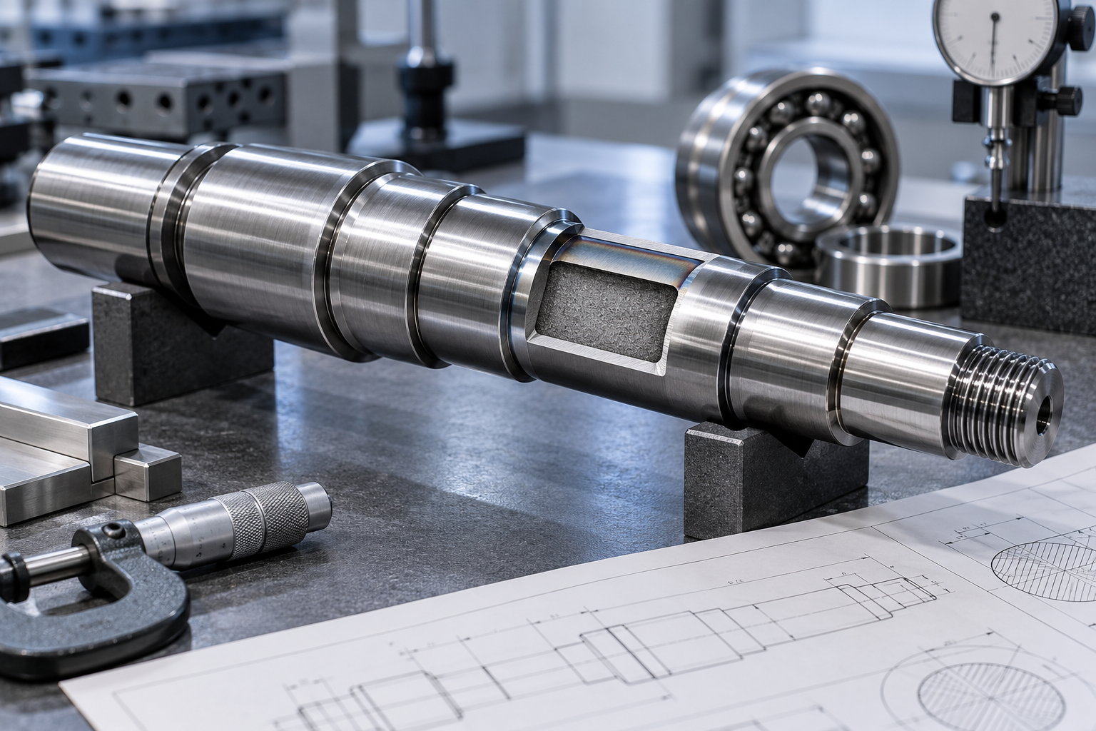
*Illustrative technical image: a finished shaft and drawing show why the hardened zone, core, and final journal geometry must be considered together. It is not a photograph of a TOPSHAFT facility.*
Start With The Function, Not A Generic Hardness Note
The correct heat treatment follows the operating problem. A bearing journal may need localized wear resistance. A loaded drive shaft may need strength and toughness through a larger section. A gear interface can need a hard working surface while the supporting core must resist shock. A corrosion-exposed shaft may instead depend on a stainless grade and a specified condition.
Writing only “heat treat to 58 HRC” leaves important questions unanswered. Which material is being treated? Which surface needs that hardness? Is the result measured at the surface, at a sectioned depth, or across the full cross-section? Does the value apply before or after grinding? Can a small non-functional area be softer? Those questions affect routing, tooling, distortion allowance, inspection, cost, and acceptance.
Start the drawing review with these functional inputs:
- The shaft material, material standard, and delivery condition.
- The loaded, sliding, rolling, or sealing surface that needs treatment.
- The required hardness range and hardness scale.
- The required case depth or effective hardened depth, if applicable.
- Whether hardening is local or extends over the full part.
- The final dimensional, form, and surface-finish requirements.
- The required test method, sampling plan, and records.
For many projects, the material cannot be separated from the treatment. A medium-carbon steel, a low-carbon carburizing steel, a through-hardening alloy steel, and a precipitation-hardening stainless steel do not respond to the same route. If the customer drawing specifies an exact grade and condition, a supplier should not silently substitute a “similar” steel. Any alternative needs design authority approval.
Choose The Treatment Route That Matches The Required Property
Different routes create different hardness distributions. The route should be selected around the functional area, the shaft cross-section, and the final manufacturing plan.
| Treatment direction | Typical reason to consider it | Key drawing questions |
|---|---|---|
| Quench and temper | Strength and toughness through a larger section | Material grade, final hardness range, section size, final machining allowance |
| Induction hardening | Localized hardening on journals, splines, or wear surfaces | Hardened band position, axial length, hardness, effective depth, transition limits |
| Carburizing or carbonitriding | Hard case with a supporting core on suitable steels | Grade, case-depth definition, areas to mask, final grinding allowance |
| Nitriding | Controlled surface hardness and wear response with limited post-process stock removal | Nitriding depth, compound-layer requirement if applicable, finish sequence |
| Precipitation hardening | Specified strength condition in suitable stainless or alloy grades | Exact condition, material specification, final property and distortion controls |
| Stress relieving | Reduce residual-stress effects between machining stages | Stage in the route, allowable final machining, dimensional verification point |
These are process directions, not automatic choices. Heat-treatment response depends on composition, initial microstructure, geometry, furnace or induction setup, quench method, and prior machining. A large stepped shaft with abrupt shoulders can behave differently from a simple small-diameter rod even when both use the same material.
Induction hardening is often discussed for shafts because it can focus treatment on a journal or spline. The drawing must show the treated region. State the axial boundaries, the relevant diameters, and whether blend zones or adjacent faces are functionally sensitive. A note such as “induction harden journal” is incomplete if the purchaser has not defined the length, depth, hardness, and final dimension of the journal.

*Illustrative technical image: a copper coil heats one defined shaft journal. It is not evidence of a TOPSHAFT process line.*
State Hardness With The Measurement Method
Hardness is a measured result, not a self-explanatory material property. A drawing should state the required range and scale, such as HRC, HRB, HV, or HK, plus the test location and the applicable test method where the project requires one. The location matters because a reading at a journal surface may not describe the core of a large shaft, and a single reading on a complex part may not represent the full condition.
Rockwell testing is widely used for acceptance and process control. ASTM E18 describes Rockwell and superficial Rockwell testing and notes that a hardness reading at one location may not represent the physical properties of the whole part. That is a practical reason to show where the test should be taken rather than writing only a number.
The reporting instruction should answer:
- What hardness scale is required?
- Where is the test location or permitted test coupon?
- Is the measured surface the delivered surface or a designated sacrificial location?
- How many readings are required, and how should the results be recorded?
- Does the value apply after final grinding, coating, or other finishing?
Very small hardened zones may need microindentation rather than a conventional surface test. ASTM E384 explains that microindentation can quantify localized hardness variations and gradients over short distances. That makes it relevant to treated cases, nitrided layers, and other areas where the condition changes rapidly from surface to core. The responsible specification must still define the acceptance criterion. A generic “microhardness check” is not sufficient on its own.
Define Case Depth Instead Of Assuming It
“Case depth” is often used loosely. It can mean the visibly altered zone, the depth to a defined hardness threshold, or a nominal processing result. Those definitions are not interchangeable. The drawing or referenced specification needs to state what depth means for the project.
For a functional case requirement, clarify at least four items:
- The depth reference: total case, effective case, or another agreed definition.
- The hardness threshold used to define effective depth, if required.
- The measuring method: sectioned metallography, hardness traverse, or another approved method.
- The measuring location and orientation on the part or coupon.
An effective case is commonly demonstrated with a sectioned sample and a hardness traverse from surface toward core. A value taken only at the surface cannot establish the depth profile. Microindentation is useful because it can evaluate hardness changes over small distances, but the sample preparation, force, spacing, and reporting requirement need to be controlled. If a coupon is used instead of the production shaft, its material, thermal exposure, and representativeness should be agreed before production.
Do not specify a deeper case merely because “more is better.” Excess depth can change distortion risk, cycle time, cost, and the balance between surface wear response and core performance. The required depth should come from contact stress, loading, material, geometry, and design validation.
Draw The Hardened Zone As A Functional Feature
For a localized treatment, use the shaft drawing to define the zone. Show the axial length, start and end positions, diameters, shoulders, reliefs, splines, or gear features that are inside or outside the treatment boundary. State whether the adjacent face, fillet, or transition area has a requirement.
This is especially important around bearing and seal interfaces. A hardened journal can meet a surface hardness requirement while a sharp transition or an unintended treated shoulder creates an assembly concern. The drawing should identify any surface that must remain machinable, retain a specific finish, or stay untreated for a subsequent operation.
Where a shaft contains several functional regions, use separate notes instead of applying one broad heat-treatment note to every feature. A rotating motor shaft may need a hard bearing zone, a controlled fit for a rotor seat, and a different requirement for a threaded end. A gear shaft can add tooth, spline, or shoulder considerations. Clear zoned callouts reduce disagreement during quotation and first-article review.
Plan The Machining Sequence Before Committing To Tolerances
Heat treatment should be planned as part of the manufacturing route. It is not simply a final external operation. Rough machining can release residual stress. Heating and cooling can change size and shape. Finish machining can remove part of a treated layer. Grinding can correct a journal dimension but must not remove more hardened material than the design allows.
For a shaft with critical journals, a practical route may include rough machining, treatment, a controlled straightening step if appropriate, and final grinding or finish machining. The exact sequence depends on the material, shaft geometry, property targets, equipment, and drawing tolerances. It should be reviewed before accepting an unusually tight diameter, straightness, or runout value.
ASM technical literature on heat-treatment distortion identifies component design, initial condition, machining procedure, and heat-treatment conditions as connected factors. That connection matters for buyers: a distortion problem cannot always be solved by asking for a tighter final inspection result. The better approach is to define the critical features early, retain appropriate finish allowance where needed, and agree on the final inspection condition.

*Illustrative technical image: a shaft is supported between centres for controlled finishing after treatment. It is not a photograph of a TOPSHAFT facility.*
Specify whether dimensions apply before or after treatment and before or after coating. For example, a bearing journal may need a final diameter and surface finish after grinding. A thread or press fit may need a separate before-coating limit. A heat-treatment note that ignores the final state can produce an inspection result that is technically true at an intermediate stage yet unsuitable for assembly.
Tie Surface Finish, Form And Treatment Together
Hardness alone does not establish a working journal. A bearing seat, seal land, or sliding surface may also need a defined finish, diameter tolerance, roundness, cylindricity, straightness, or runout. These controls interact.
For a bearing journal, connect the treatment note to the bearing journal specification guide, the shaft surface-finish guide, and the shaft runout tolerance guide. The part should be evaluated as a system: material condition, local hardness, final surface, datum relationship, and inspection method.
Avoid applying a strict finish to every surface by default. Functional lands deserve focused requirements. Non-contact clearance diameters may not. This makes the drawing clearer and can prevent unnecessary processing cost.
Define Inspection Records During Quotation
Inspection evidence should be part of the order review, not an afterthought. Ask for the specific records that the project needs. Depending on the agreed scope, this may include a material certificate, heat or lot traceability, treatment certificate, hardness report, case-depth report, dimensional report, first-article report, or certificate of conformity.
The buyer should also define the sampling logic. Is hardness checked on every part, by lot, on a coupon, or only during first article? Are test locations allowed on a non-functional extension? Is destructive sectioning permitted on a representative coupon? These choices affect cost and lead time, so they belong in the RFQ when they are mandatory.
TOPSHAFT’s inspection and quality capability is designed around drawing-defined dimensions and agreed records. For a treatment-controlled shaft, submit the drawing with the material, property, and documentation requirements so that the manufacturing and inspection route can be reviewed together.
Common Specification Mistakes To Avoid
Specifying hardness without a scale or location. A number alone does not define the instrument, test point, or acceptance basis.
Calling for case depth without a definition. State whether the requirement is total or effective depth, the threshold if applicable, and the verification approach.
Treating all shaft surfaces as equal. Identify the functional journals, splines, teeth, or contact zones. Do not impose the same treatment and finish everywhere unless the design requires it.
Ignoring the post-treatment process. Tight journals may need finish stock and a final grinding route. The drawing must allow it.
Accepting a material substitution by name alone. A proposed alternative may change hardenability, distortion behavior, corrosion resistance, or documentation. Obtain engineering approval.
Requesting reports after the purchase order. If traceability or destructive case-depth verification is required, define it at quotation and order review.
A Drawing Note Checklist For Shaft Heat Treatment
Before requesting a quote, check that the package answers the following questions:
- What material grade, standard, and starting condition apply?
- Which treatment route or final metallurgical condition is required?
- Which surfaces require treatment, and what are the exact zone boundaries?
- What hardness range, scale, and test location apply?
- Is case depth required? If so, how is it defined and verified?
- Which dimensions and finishes apply after treatment and final grinding?
- What straightness, runout, or datum relationships remain critical after treatment?
- What records, samples, coupons, and inspection reports are required?
- What quantity and project stage apply: prototype, validation, or repeat production?
Frequently Asked Questions
Can A Shaft Be Heat Treated After Final Machining?
It can, but the route must account for dimensional change, distortion, and potential surface changes. Critical features often require final finishing after treatment.
Is A Higher HRC Value Always Better For A Shaft?
No. The required hardness depends on wear, load, toughness, fatigue, material, geometry, and the mating component. Excess hardness can be inappropriate for some applications.
How Is Case Depth Checked?
The agreed method may use a sectioned specimen and a hardness traverse. The drawing must define the case-depth basis, measuring location, and acceptance criterion.
Can Only One Journal Be Induction Hardened?
Yes, localized hardening can be reviewed for a defined journal or feature. The drawing should state the treated area, hardness, depth, transition limits, and final dimensional condition.
Ready To Review Your Shaft Requirement?
Send the shaft drawing, material and treatment requirements, functional zones, quantity, tolerance and inspection needs for a practical manufacturing review. If a heat-treatment route or material alternative is still open, include the load, wear, corrosion, temperature, and mating-component information that affects the decision.
---
Source Notes For The Draft
- ASTM E18: Rockwell hardness testing
- ASTM E384: Microindentation hardness testing
- NIST Recommended Practice Guide: Rockwell hardness measurement
- ASM Handbook: Control of distortion in tool steels
Draft Quality Scorecard
| Dimension | Score (1-10) |
|---|---|
| Search Intent | 9.7 |
| SEO Keyword Coverage | 9.6 |
| Technical Accuracy | 9.6 |
| Content Depth | 9.7 |
| AI Search / GEO | 9.6 |
| Readability And Structure | 9.6 |
| Internal Linking | 9.7 |
| E-E-A-T | 9.6 |
| Commercial Conversion | 9.6 |
| Overall | 9.6 |