
Shaft Case Depth Inspection: Define Your Requirements
Shaft case depth inspection needs a defined depth criterion, representative specimen locations and an identified surface reference. Surface hardness alone cannot establish the hardness profile beneath your journal. Agree the measurement and acceptance basis before ordering hardened shafts or approving a laboratory report.
Define Which Depth You Need
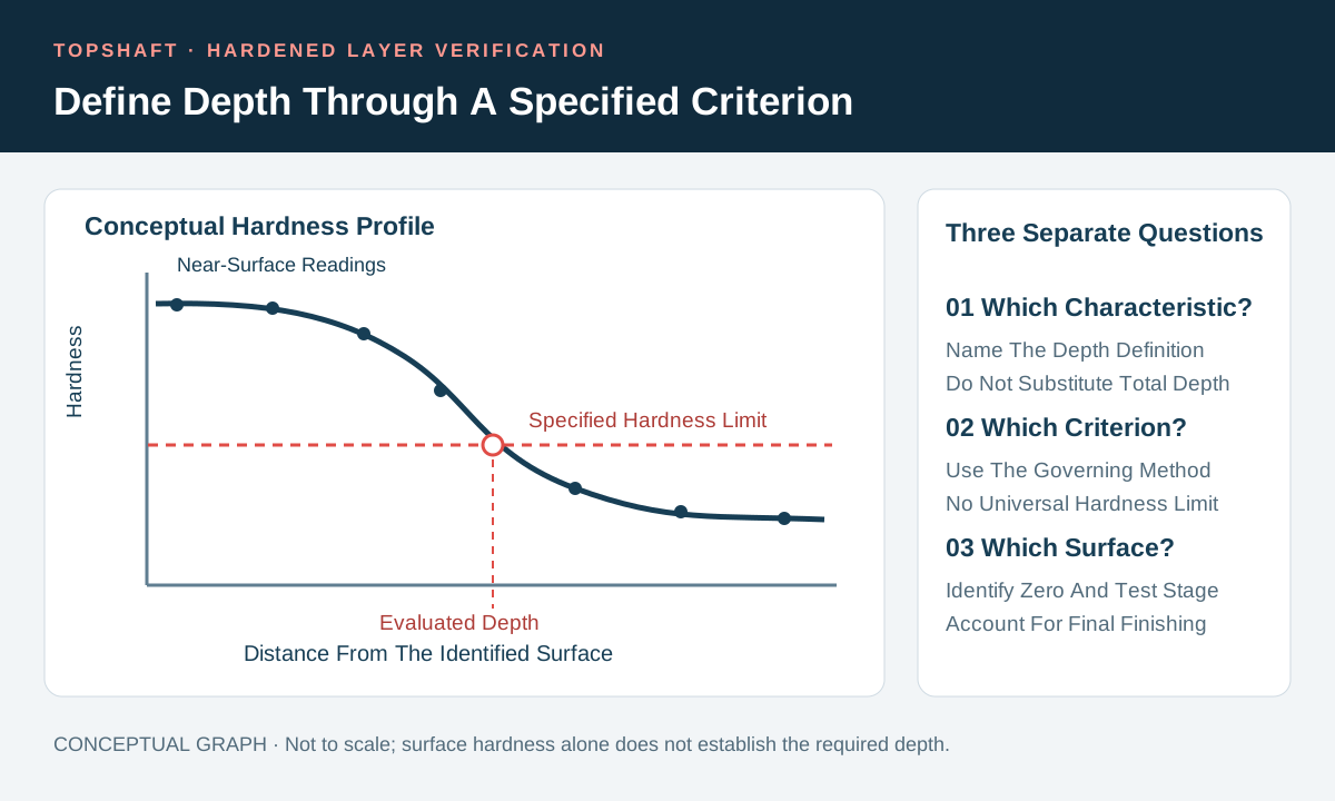
Your case depth requirement should name the measured characteristic rather than provide an unexplained depth number. Case hardening depth, surface hardening depth and nitriding hardness depth follow different evaluation concepts. Total hardened-layer thickness is another characteristic. Do not treat their abbreviations or reported values as interchangeable.
ISO 18203:2026 covers several depth determinations for surface-hardened steel layers. Its scope includes thermal and thermochemical treatments. Select the applicable definition through your engineering requirements and contractual documents. The standard's public scope does not supply a complete laboratory procedure or establish your shaft's acceptable depth range.
State the required limits, units and applicable edition on the controlled specification. Resolve legacy drawing terminology before quotation. A supplier should not choose whichever definition produces a favorable result. Use your heat treatment specification to connect the required final condition with the inspection characteristic. Keep process instructions and measured acceptance requirements distinguishable.
Separate Surface Hardness From The Depth Profile
Your surface hardness result and case depth result answer different questions. A surface measurement characterizes hardness at its test location under its method. A depth determination investigates the specified change beneath an identified surface. One compliant surface reading does not demonstrate that the hardened layer reaches the required depth.
For hardness-based depth determination, you need readings associated with known distances into a prepared section. The evaluation uses the applicable hardness criterion and method. Struers explains this relationship in its Vickers hardness guidance. Keep the measured hardness values and their positions available, rather than retaining only the calculated depth.
Specify core hardness separately when your design requires it. Avoid using a depth result as a substitute for every material property. The relevant alloy, treatment condition, geometry and requirements affect your verification plan. Consult your hardness location and reporting guide when defining separate surface or core checks. Keep their identities linked without merging their acceptance rules.
Match The Definition To The Treatment
Your depth evaluation should match the treatment and its governing requirements. Carburized, induction-hardened and nitrided shafts should not automatically share one threshold or calculation rule. Identify the actual treatment condition before selecting the measurement. Ask the laboratory to confirm the applicable definition and any limitations.
Do not assume every depth requirement uses the same fixed Vickers limit. Some definitions use a specified hardness threshold; others depend on different reference conditions. Obtain the governing instructions and engineering decision. This article deliberately avoids prescribing a universal threshold. A familiar value from another drawing may describe a different treatment or contractual requirement.
Keep nitriding hardness depth separate from compound-layer thickness where both are required. A visible boundary does not automatically establish a hardness-based depth. Equally, a hardness traverse does not answer every microstructural question. Identify the characteristics that matter to your application. Require separate results where the specification calls for different measurements.
Identify The Surface That Starts The Measurement
Your inspection plan should state which manufacturing surface defines zero depth. Identify whether the result represents the treated surface or the finished surface after material removal. Grinding changes the location from which remaining layer depth is measured. Do not compare reports from different reference surfaces as though they were equivalent.
ISO 15787:2016 addresses presentation of the final condition of heat-treated ferrous parts on drawings. Use controlled documentation to connect treatment, finishing and acceptance requirements. Mark any required intermediate condition separately. A note saying case depth after treatment may leave final grinding consequences unresolved.
A simple subtraction may illustrate the geometry, but it does not independently verify the finished hardness profile. Actual removal, location and processing effects need consideration. Ask engineering which evidence establishes the final requirement. Connect the plan to your surface finish specification. Do not approve additional grinding solely because an earlier report showed sufficient depth.
Choose Representative Section And Traverse Locations
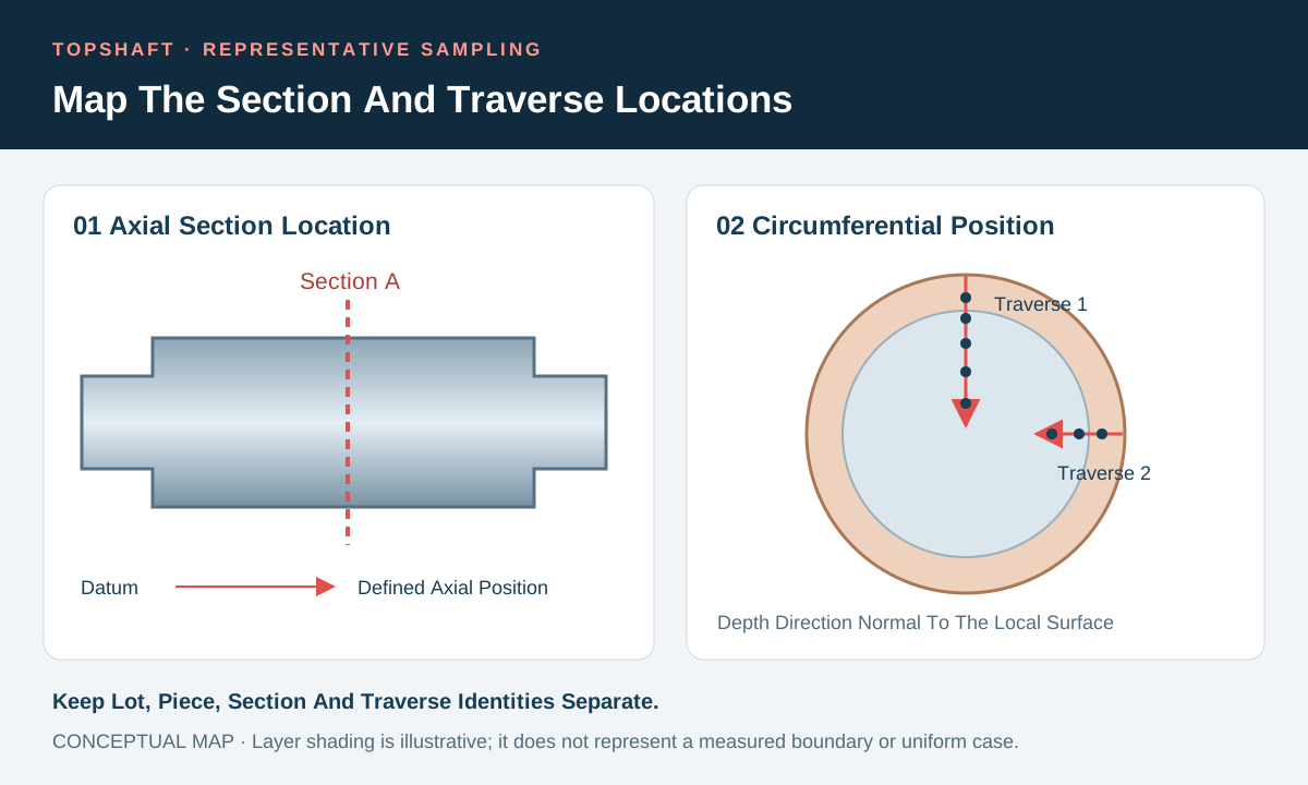
Your sampling plan should identify where each section and hardness traverse comes from. State axial position, circumferential position and relevant shaft feature. A journal midpoint result does not automatically describe a shoulder transition or groove. Mark the required locations on a drawing or controlled specimen map.
Keep section orientation and measurement direction explicit. Depth normally needs the direction required by the governing method, referenced to the relevant surface. An oblique distance can differ from the intended depth. Curved journals and local transitions need suitable preparation and location control. Ask the laboratory to describe its arrangement before destructive sampling begins.
Distinguish specimen quantity from spatial coverage. Several traverses on one section do not represent several delivered shafts. Conversely, samples from several pieces may leave a critical feature unexamined. State the lot, selected pieces and locations independently. Use your inspection sampling plan to define the agreed basis without claiming certainty for every untested location.
Agree Destructive Sampling And Witness Specimen Limits
Your order should authorize destructive sampling and define what the chosen specimen can represent. Sectioning a delivered shaft changes its usability. Agree sacrificial pieces, replacement quantities and disposition before scheduling the work. Purchasing should include these consequences in the quotation, rather than discovering them when the laboratory requests material.
A witness specimen can support an agreed verification plan, but its relationship to the shaft needs justification. Material, geometry, treatment exposure and subsequent processing may differ. A coupon sharing the furnace load does not automatically reproduce every shaft feature. Ask the responsible authority to approve its intended use and limitations.
Keep qualification evidence separate from routine production evidence. A development section may demonstrate one setup under identified conditions. It does not automatically cover later changes or every production lot. Link significant changes to your manufacturing change review. Confirm whether material, geometry, processing or sampling changes require renewed evidence.
Preserve The Edge During Specimen Preparation
Your preparation method should preserve the surface reference and permit reliable indentation measurement. Cutting damage, edge rounding or poor polishing can undermine a traverse. Ask how the laboratory controls these risks for the actual specimen. Do not describe preparation as an unimportant step before the real inspection.
Struers' hardness testing guidance explains how surface preparation affects reliable indentation measurement. The relevant principle is preserving the feature you intend to measure. It does not justify copying one preparation recipe across every alloy or geometry. The laboratory should select and control its applicable preparation method.
Require specimen orientation and identity to survive cutting, mounting and transfer. A polished section without a known original surface or location cannot establish the intended result. Retain a suitable specimen image when required. Document preparation concerns before evaluation. Repeating measurements on an unsuitable edge does not necessarily resolve the underlying problem.
Specify The Hardness Traverse And Evaluation Basis
Your traverse specification should identify the hardness method, test conditions and evaluation rule. The selected force, indentation spacing and distance measurement must suit the applicable method. Let the competent laboratory establish compliant details under the governing instructions. Do not prescribe arbitrary tiny spacing merely to make the graph look more detailed.
ISO 6507-1:2023 specifies the Vickers hardness test method and describes optical measurement limitations. ASTM E384-22 addresses microindentation hardness testing, including sources of error. Neither citation alone defines your complete case depth acceptance requirement. Keep the depth definition, hardness procedure and product limits connected in the contract.
State how the applicable method determines the crossing between measured points. Preserve the actual readings around the relevant criterion. Do not invent an unmeasured crossing because the recorded traverse stopped too early. When data are insufficient, obtain an authorized laboratory decision. Report any justified additional measurements and their relationship to the original traverse.
| Inspection Element | What You Should Agree | Evidence To Retain |
|---|---|---|
| Depth characteristic | Applicable definition and limits | Controlled specification and edition |
| Surface reference | Treated or finished condition | Manufacturing stage and zero reference |
| Sampling | Lot, pieces, sections and traverses | Specimen identities and location map |
| Measurement | Hardness method and evaluation rule | Distances, readings and calculated depth |
| Acceptance | Applicable limits and decision authority | Result comparison and authorized disposition |
| Delivery | Final condition and report package | Traceability and release checks |
Evaluate The Profile Before Accepting The Summary
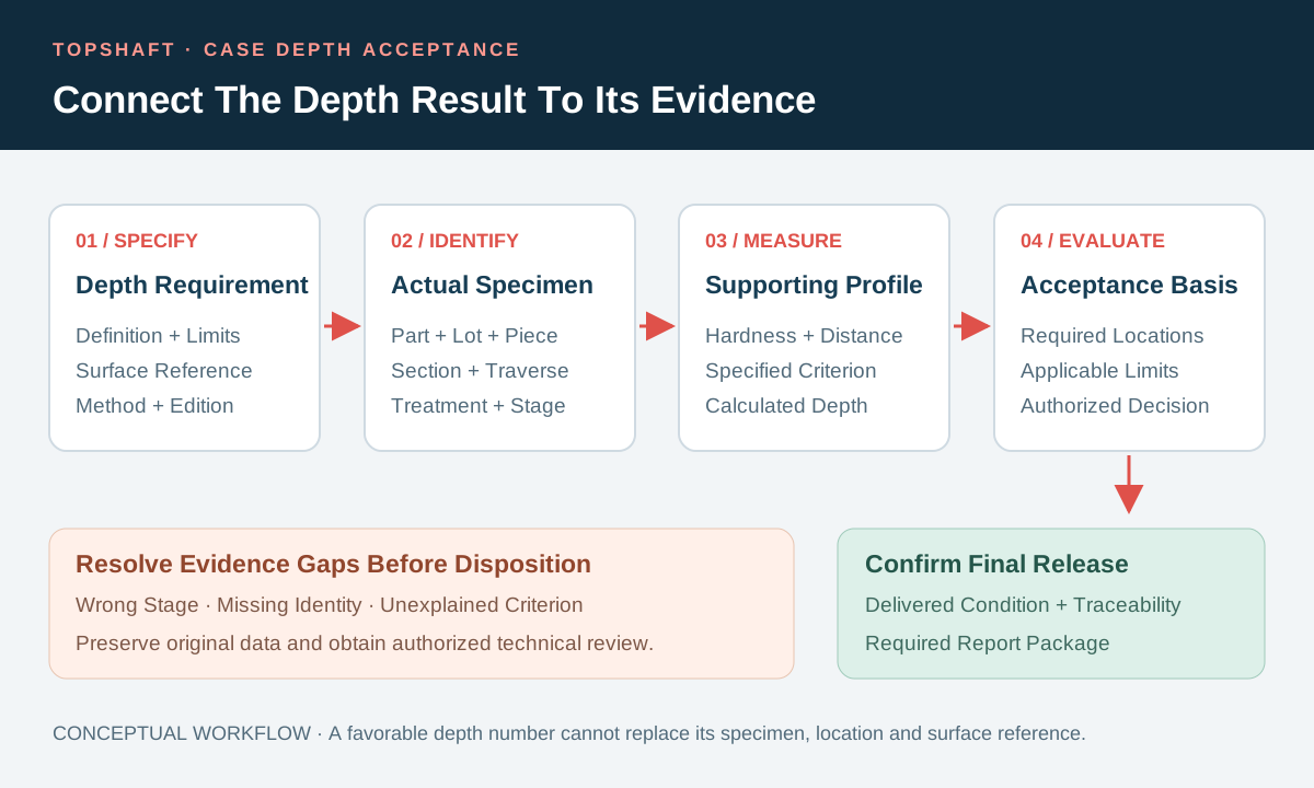
Your review should connect the reported depth to the actual profile and required location. Check specimen identity, units, hardness designation and surface reference first. Then compare the calculated result with the specified limits. A passed label cannot resolve missing locations or an unstated definition.
An unusual profile needs technical review rather than selective deletion of inconvenient readings. Ask the laboratory to investigate preparation, location or measurement concerns through its controlled process. Preserve the original data and authorized interpretation. Do not average unrelated locations unless the applicable requirement permits that evaluation. A favorable mean can conceal a local failure.
For example, a hypothetical order requires a finished-journal result, but the report describes a pregrinding specimen. Keep that difference visible. Ask engineering whether the evidence establishes the final requirement or needs additional verification. Do not relabel the earlier result. This example illustrates a purchasing review issue, not a TOPSHAFT production case.
Link The Report To The Delivered Shafts
Your report should identify the material and production population represented by each specimen. Include the part reference, drawing revision, lot and specimen identity. Record the treatment condition, manufacturing stage and sampling arrangement. Link section images and traverse data to the same identified record. A detached graph cannot establish which order it represents.
Retain the invoked methods, relevant test conditions, depth definition and actual results. Include exclusions, departures and required review decisions. Use your material traceability plan to maintain the connection through outside processing and laboratory transfers. A shared alloy name does not establish a shared production history.
Hold disputed results for authorized disposition. Your rework and concession process should distinguish proposed correction from approved action and verified completion. Further treatment or material removal may affect other requirements. Agree follow-up verification before proceeding. Preserve both original evidence and the final authorized conclusion.
Prepare A Confirmed TOPSHAFT Inquiry
Your inquiry should support confirmation of a feasible manufacturing and inspection arrangement before order acceptance. Send the released drawing, alloy, treatment condition and required depth characteristic. Identify the surface reference, critical features and acceptance limits. Include quantities, annual demand, destructive sampling expectations and report requirements. Mark unresolved engineering questions clearly.
This article does not establish particular TOPSHAFT heat treatment equipment, laboratory instruments, certifications or case depth testing services. Confirm the proposed internal or external arrangement during quotation. Ask who approves sampling, evaluates results and authorizes departures. Keep technical responsibilities visible alongside the commercial agreement. Do not infer a guaranteed capability from an educational guide.
Depth limits, geometry, specimen access, sacrificial quantities and reporting can affect cost and scheduling. Ask for confirmation against your actual drawing rather than relying on generic prices. Use the shaft RFQ checklist to assemble a consistent package. Confirm which evidence will accompany delivery and how any remaining uncertainty will be resolved.
Frequently Asked Questions
Your purchasing decisions should follow the specified depth definition, representative sampling and applicable measurement method. These answers clarify scope without replacing laboratory instructions.
Does Surface Hardness Prove Case Depth?
No. Surface hardness and depth describe different characteristics. A compliant surface reading does not establish the hardness distribution beneath it. Require the specified depth measurement and its supporting evidence.
Are Effective Depth And Total Depth Interchangeable?
No. They use different definitions and may require different evaluation. Name the intended characteristic, units and limits. Resolve an unexplained case depth note before examination or quotation.
Does Every Treatment Use The Same Hardness Limit?
No. The applicable treatment, definition and governing documents determine the criterion. Do not transfer a threshold from another drawing without technical confirmation. Identify the rule before interpreting the profile.
Should Depth Start At The Finished Surface?
Use the surface required by the controlled specification. Identify whether the result represents treatment completion or subsequent finishing. Do not silently compare measurements from different manufacturing stages.
Can A Witness Coupon Replace A Shaft Section?
Only within an approved verification basis. Its material, geometry and processing relationship need consideration. Sharing a treatment batch does not automatically prove equivalent depth at every shaft feature.
Is A Hardness Traverse Nondestructive?
A cross-sectional traverse normally requires specimen preparation that changes the sampled part. Agree destructive sampling and sacrificial quantities beforehand. Other proposed techniques need separate validation for the intended requirement.
Can One Traverse Represent Every Shaft Feature?
Not automatically. Its location establishes the evidence boundary. Define critical sections, circumferential positions and selected pieces separately. Keep unexamined features visible in the sampling and acceptance plan.
What Information Supports A Useful Quote?
Send the drawing, alloy, treatment, depth definition, limits, surface reference, specimen plan and quantities. Include reporting and approval responsibilities. Ask TOPSHAFT to confirm the proposed arrangement and limitations.
Send Your Case Depth Requirements
You can reduce ambiguity by agreeing the depth definition, surface reference, specimen locations and acceptance basis before ordering. Contact TOPSHAFT with your drawing and inspection package. Request confirmation of sampling, reporting and final release responsibilities.