
Shaft Hardness Testing: Locations, Methods and Acceptance Reports
A shaft inspection report can contain an acceptable hardness number and still leave an important question unanswered: where was that number measured? A reading from an end face does not automatically describe a bearing journal. A result before final grinding does not necessarily establish the condition of the delivered surface. For an OEM buyer, a useful hardness requirement connects the specified material condition, the feature of interest, the measurement method and the evidence needed for acceptance.
This guide is about preparing that inspection agreement, not selecting a universal hardness for every shaft. It complements the broader shaft heat-treatment specification guide. Product geometry, material, treatment and service requirements differ, so the responsible design and quality teams must approve the actual limits and procedure. Nothing here asserts that TOPSHAFT provides a particular laboratory service, accreditation or destructive testing capability; confirm the available scope during quotation.
1. Start with the Property You Need to Verify
Write down whether the requirement concerns the finished surface, the core, a locally hardened region or a hardness profile through a treated layer. These are different questions. A single surface reading cannot by itself establish a through-section distribution. Likewise, a sectioned hardness traverse provides information along its defined path, not unrestricted proof of every point on every delivered component.
Connect the requirement to its engineering purpose without using hardness as a substitute for complete validation. A drawing may require a controlled material condition, while an application also depends on geometry, lubrication, residual stresses and loading. Passing a hardness check alone does not establish fatigue life, wear life or suitability for a particular assembly. Record who owns the design decision and who approves any departure from the stated inspection plan.
2. Specify the Method, Not Just a Number
State the hardness scale or method, the applicable standard and its agreed edition, the acceptance range and any additional reporting notation required by that method. A number without its scale is incomplete. Do not silently substitute one method because a preferred instrument is unavailable. Ask the testing party to confirm suitability for the shaft material, thickness, geometry and expected hardness before committing to an acceptance route.
Rockwell, Vickers and other hardness methods are not interchangeable labels. ISO 6507-1:2023 describes the Vickers method for metallic materials. The standard reference identifies a method; it does not supply the application-specific target for your shaft. Where a conversion is proposed, identify the conversion basis and obtain approval rather than treating a converted value as a directly measured result. Keep original readings and their method in the report.
3. Put Test Locations on a Controlled Sketch
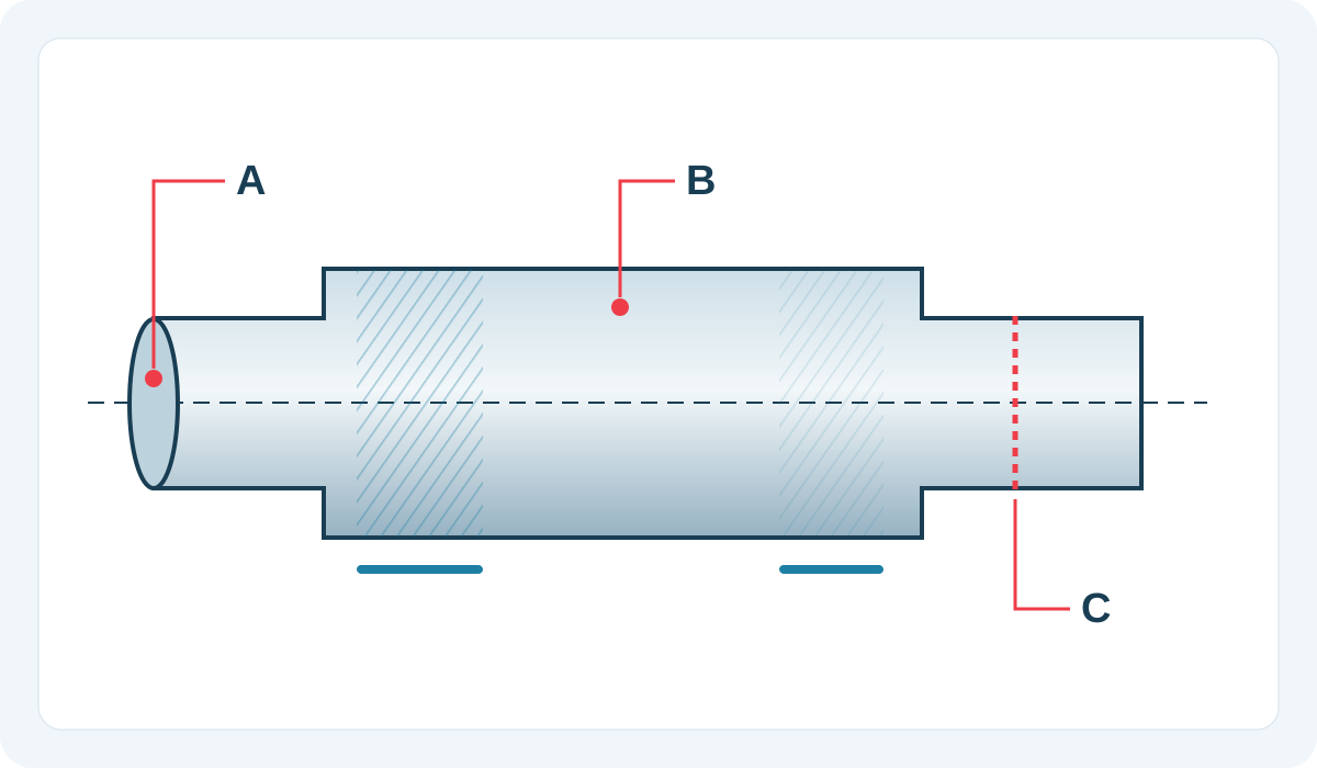
Give each proposed zone an identifier linked to the drawing revision: for example, A for an approved end-face area, B for a specified journal location and C for a section taken from a designated sacrificial part. Define axial position, circumferential position when relevant, and the relationship to treated and untreated boundaries. Avoid an instruction such as “test anywhere convenient,” which can make otherwise tidy records impossible to interpret.
Check whether an indentation is permitted on the delivered feature. A bearing seat, seal track, thread or highly stressed transition may need protection from test marks or preparation damage. The design authority should approve a suitable alternative, additional stock, a sacrificial component or another agreed route when direct testing conflicts with function. A convenient location is not automatically representative; document the reason for using it and the limitations of the evidence.
4. Review Curvature, Support and Preparation
A round shaft introduces practical measurement issues that a flat reference block does not reproduce. Confirm that the chosen method and fixture can support the component securely, access the location and satisfy the method's relevant geometry requirements. Identify how surface condition, local thickness and proximity to edges or existing impressions will be addressed. Do not copy a correction or spacing rule from an unrelated method or instrument.
The NIST Rockwell hardness measurement guide discusses measurement influences including curved surfaces and specimen preparation. Use the applicable current test standard and an approved procedure for the actual job. Preparation should not unintentionally change the material condition being assessed. If material is removed to create a test surface, record where, how much and why that surface still answers the inspection question.
5. Define the Manufacturing Stage
Identify when the test is performed relative to hardening, tempering, straightening, grinding and any coating operation that applies to the order. A report should distinguish a process-control check from a final acceptance check. If the contract requires evidence after a particular operation, an earlier result needs explicit approval before it can be used in its place. Maintain the relationship between the part's condition and the date of measurement.
For a surface-treated shaft, discuss how later stock removal or subsequent processing affects the feature being verified. Do not assume that a pre-grinding reading answers a final-surface requirement. Conversely, do not demand a direct indentation through a coating without confirming that the method will assess the intended material. Resolve these details in the order's inspection plan, together with the final dimensions described in the coating specification checklist.
6. Keep Surface Hardness Separate from Case Depth
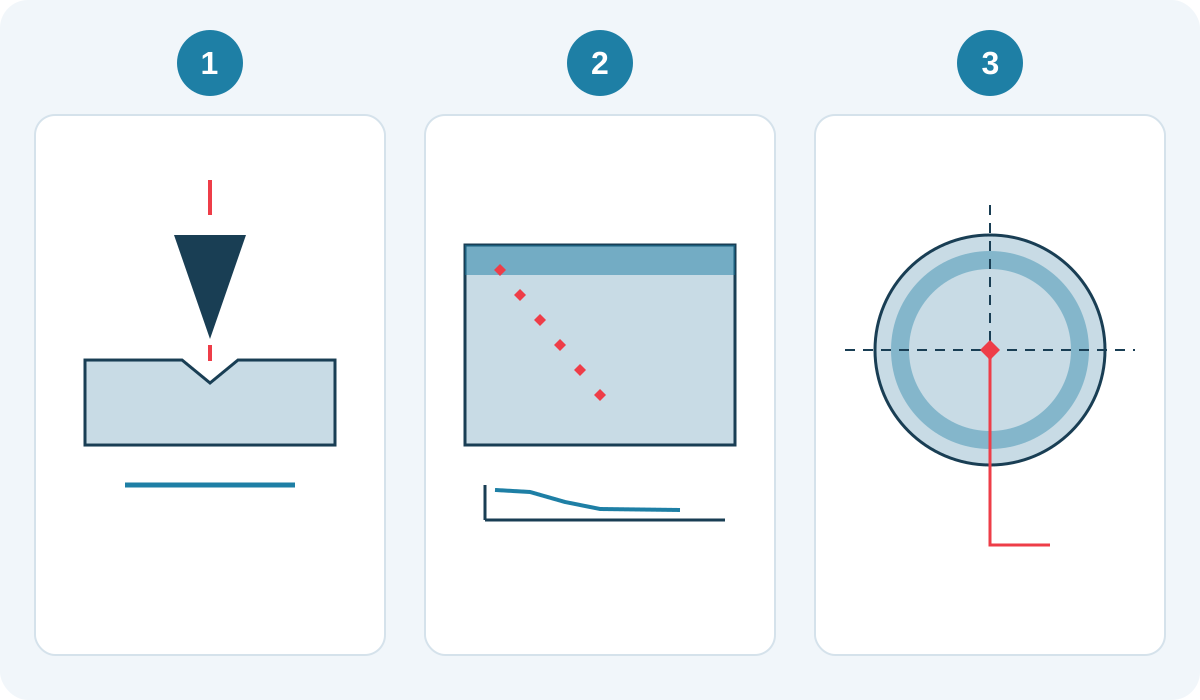
When a hardened layer is required, specify both the relevant hardness requirement and the agreed definition of depth, if depth is part of acceptance. “Case depth” alone is not a complete instruction. Identify the applicable evaluation method, reference surface, acceptance criterion and section orientation. A depth defined by a hardness threshold is not necessarily the same as a total depth identified by another metallurgical criterion.
If a hardness traverse is required, agree the specimen source, section location, preparation, measurement path and report format with the testing party. Show positions relative to the finished reference surface and retain the individual readings rather than only a pass statement. Sectioning can consume the specimen, so include the required sacrificial quantity, approval timing and ownership of retained samples in the purchase agreement before production begins.
7. Decide What a Coupon Can Demonstrate
A test coupon may be useful, but it is not automatically equivalent to the finished shaft. Ask how its material identity, section size, processing history and position in the relevant batch are connected to the parts. Describe which requirement the coupon is intended to verify. If it is only process evidence, label it accordingly instead of presenting it as a direct measurement of the delivered journal.
Agree when actual component testing is necessary and when an approved representative specimen is acceptable. The decision belongs in the inspection agreement, not in a last-minute shipping conversation. Tie sample identities to the relevant material and processing records using the principles in the shaft traceability checklist. Keep any claimed representativeness bounded by the agreed plan, especially when geometry or processing conditions change.
8. Agree Sampling and Retest Rules in Advance
Define the lot, the selected components, the locations per component and the required readings at each location. Distinguish repeated readings on one shaft from measurements across several shafts. Those arrangements provide different coverage. A plan should also explain who selects the samples, how identification is maintained and what happens when results are missing, ambiguous or outside the agreed range. There is no universal sample quantity suitable for every order.
Do not average away an unacceptable individual reading unless the approved acceptance rule specifically permits the relevant calculation. State how retests, invalid tests and nonconforming material will be handled, including authorization and disposition. Preserve original results and the reason for excluding a reading. For near-limit decisions, connect the plan with the measurement uncertainty and acceptance guide; rounding and reporting precision should not silently alter a contractual boundary.
9. Use a Report That Can Be Audited
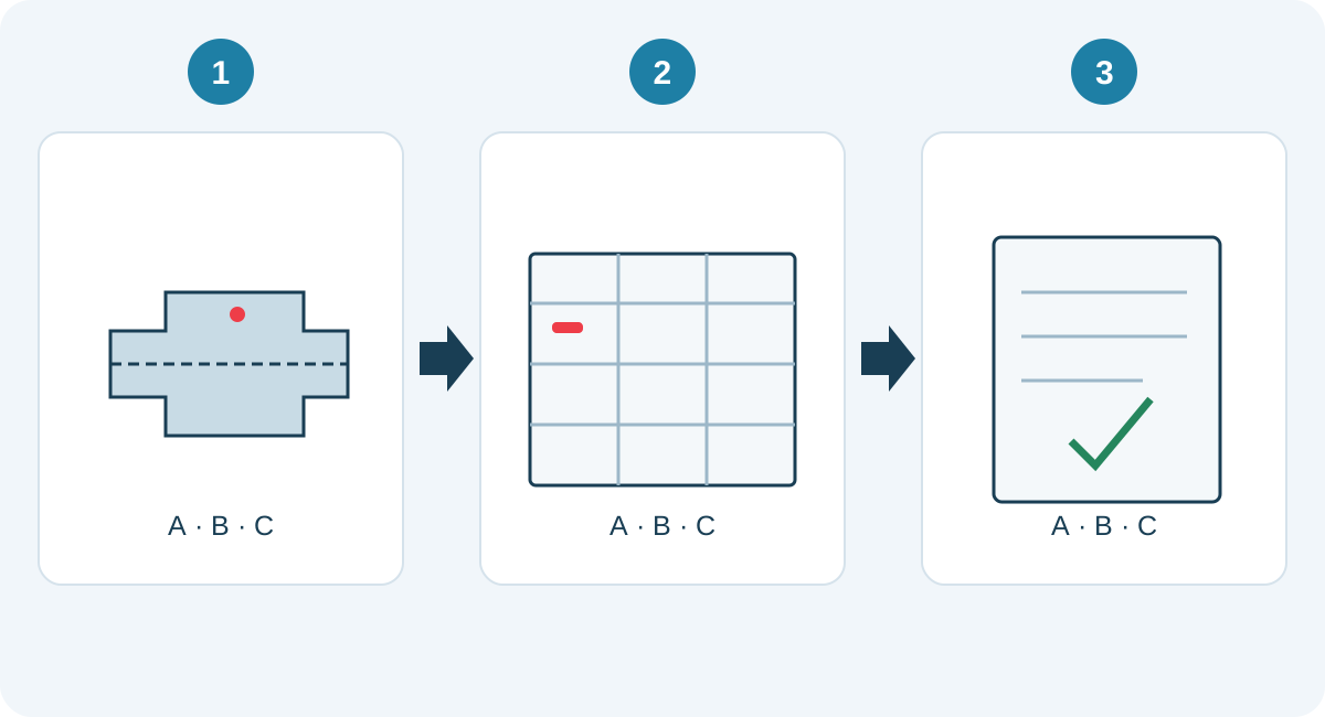
The following table is an RFQ discussion template, not a prescribed inspection standard or a promise of included testing. Replace descriptive placeholders with approved order-specific instructions. Request an example report before ordering when report structure matters to your approval process. A blank field should lead to clarification, not an assumption that a missing detail is unimportant.
| Report field | What to connect | Question before approval |
|---|---|---|
| Part and revision | Shaft identity and controlled drawing | Which physical component was tested? |
| Method and condition | Scale, procedure and processing stage | Does the reading assess the intended property? |
| Location and specimen | Zone identifier, position and sample source | Is this a component result or representative evidence? |
| Individual results | Readings, units or scale notation, permitted corrections | Is any conversion clearly distinguished? |
| Acceptance and disposition | Limits, decision rule, deviations and authorization | What supports the final release decision? |
An RFQ should also separate the commercial consequences of the inspection route. Ask whether the quoted price includes specimen preparation, outside testing, replacement of sacrificed parts and the requested report language. Agree how long physical specimens and raw records must be retained, who can request them and what happens if a later investigation requires additional work. Where a report references another certificate, ensure the referenced document can actually be retrieved and tied to the same order. These administrative details do not improve a measurement by themselves, but they prevent a technically acceptable test from becoming unusable evidence because its identity, supporting records or approval status cannot be established. Record agreed exclusions explicitly rather than discovering them after the shipment is ready.
10. Close the Loop Before Release
Before shipment, compare the report with the approved drawing and inspection plan rather than checking only for the word “pass.” Confirm that test marks or specimen removal have not compromised parts intended for delivery. Where an external laboratory is involved, agree the chain of identification and the evidence supplied with the shipment. Ask who reviews the report and who can authorize a deviation; a supplier signature alone does not change the drawing.
Keep the first-article approval and routine production requirements distinct. An approved sample is a reference for its agreed scope, not permission to omit future checks. For a custom shaft enquiry, send the drawing revision, material condition, location sketch, method requirements, sampling expectations and report needs together. A clear package allows the manufacturer to confirm feasibility, exclusions, cost and lead time without inventing missing acceptance criteria.
Frequently Asked Questions
Is one hardness reading enough for a complete shaft?
Not automatically. The answer depends on the specified property, treatment pattern, location and approved sampling plan. A local reading should not be represented as evidence of every region unless the inspection agreement justifies that conclusion.
Can a hardness conversion replace the specified test?
Only when the responsible parties approve the substitution and its basis. Keep the original method and readings visible, identify converted results and do not imply that conversion is identical to direct measurement.
Can the test be made on an unused end face?
Possibly, if the location is suitable for the method and representative of the agreed requirement. Obtain approval for its position and preparation; being nonfunctional does not alone establish representativeness.
Does a hardness pass prove the shaft will last in service?
No. Hardness is one characteristic. Service suitability depends on the complete design, material condition, geometry, loading, assembly and operating environment. Keep inspection acceptance separate from application validation.