
Cross-Drilled Shafts: Hole Location, Intersections and Inspection
A radial hole can look like a minor detail on a shaft drawing. Yet the same diameter can describe a pin connection, an oil passage, a locking feature or an access opening, each with different acceptance needs. The external opening may be easy to see while its intersection with an axial bore is hidden. A hole that meets its diameter requirement can still be in the wrong axial position or angular relationship to another feature.
This guide helps OEM buyers and engineers prepare a complete cross-hole requirement before quotation. It does not prescribe a universal drill size, wall thickness, cutting process or fatigue limit. The design authority must approve the functional requirements and any change to the shaft. Confirm the manufacturing, cleaning and inspection scope with TOPSHAFT rather than assuming a particular machine, internal deburring method or testing capability is included.
1. State What the Hole Is Intended to Do
Identify whether the hole locates or retains a component, transmits a load, carries fluid or merely provides access. Share the relevant mating part and assembly requirements. Do not assume that a hole suitable for an oil route is automatically suitable for a fitted pin. The manufacturer needs the approved drawing requirement, not an invitation to select the joint design from a vague description.
Describe whether the hole is radial, diametral, offset, angled, blind or through the required walls. Use a section or additional view when the path is not obvious. For a hollow shaft, identify whether one opening enters the central bore or continues through the opposite wall. The hollow-shaft bore guide complements this information, but an axial bore specification alone does not define the cross-hole connection.
2. Define the Actual Hole Size and Final Condition
State the required hole dimension, tolerance and any applicable form or finish requirement using the agreed drawing system. Distinguish a clearance opening from a controlled mating feature. If a subsequent operation changes the hole, specify the final delivered condition rather than only the initial drilling size. Do not add a fit designation without confirming the mating requirement and the inspection basis.
For a blind hole, distinguish the required useful depth from the drill-point region or other termination geometry when relevant. For a through hole, make the intended breakout explicit. A tool passing through once does not by itself establish every geometric characteristic of both openings. If the hole is threaded, use the shaft thread checklist to define thread form, engagement, end condition and acceptance rather than treating a tap-drill size as the finished specification.
3. Locate the Hole from Controlled References
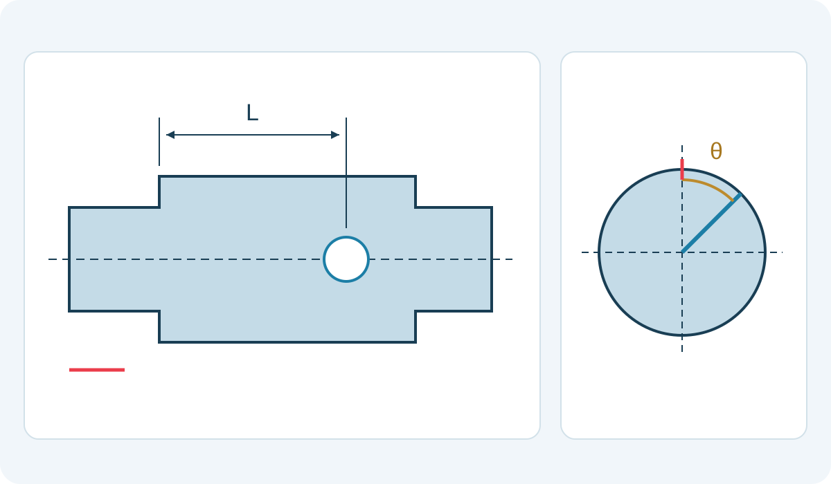
Define axial location from a specified face, shoulder or datum system that represents the intended assembly. Identify the axis or feature used to control the hole's relationship to the shaft. A chain of unrelated reference lengths may not establish the functional location clearly. The shaft datum guide helps connect drawing references with the physical inspection setup.
Where positional or orientation controls are needed, the responsible engineer should specify them consistently with the drawing standard. Do not improvise a geometric tolerance from a plus/minus location dimension during quotation. Check the final drawing and model for conflicting definitions, and distinguish informational dimensions from acceptance controls. A supplier should be able to identify exactly which requirement governs the reported hole position.
4. Do Not Leave Angular Orientation to Assumption
If the cross hole must align with a keyway, flat, spline feature or another hole, identify the angular reference and the required relationship. A circular shaft without a defined indexing feature does not provide a unique rotational zero simply because it is shown horizontally on a page. Include an end view or clear three-dimensional definition when the relationship cannot be understood from the side view.
State whether several holes share a pattern or have individual location requirements. Clarify symmetry and repeated-feature notation instead of asking the manufacturer to infer them from an illustration. Define which end is viewed and which direction establishes the angle when that distinction matters. These details prevent an apparently reasonable mirror-image interpretation from becoming an incorrect component after the rest of the shaft is finished.
5. Show Every Internal Intersection
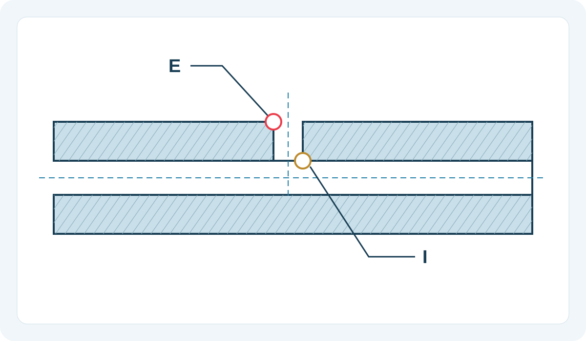
Use a section or detail to identify where the hole meets another passage, cavity or external feature. Mark the internal edge separately from the accessible entry edge. The design review should consider the actual intersecting geometry, not only the hole-center lines. A small offset can change the remaining wall or the shape of the opening, so any required relationship must be defined by the approved drawing.
Sandvik Coromant's guidance on irregular-surface drilling treats cross-hole drilling as a specific machining situation. Use this as a reason to discuss the manufacturing route, not to impose a universal tool or cutting recipe. The selected process depends on the actual material, geometry and sequence. Any change made to improve access or manufacturability still needs design approval when it affects a controlled requirement.
6. Specify Edge Condition Beyond “Deburr”
Identify which entry, exit and internal intersection edges need control. State the permitted edge condition using an approved requirement, rather than leaving an inaccessible intersection covered only by a general note. The shaft deburring guide discusses this wider issue. A visibly clean outer edge is not evidence that an internal breakthrough has the same condition.
If a defined chamfer or radius is required, specify its geometry and location. Where an undefined-edge indication is used, identify the applicable standard and edition. ISO 13715:2017 addresses indication and dimensioning of edges of undefined shape; citing it is not the same as supplying an order-specific edge limit. Avoid authorizing unlimited material removal under the phrase “break all edges,” particularly near functional surfaces or a required wall section.
7. Review the Shaft Around the Opening
The design authority should review the hole in the context of shaft loading, surrounding section and nearby shoulders, grooves, threads or other features. This guide provides no universal safe edge distance or minimum wall. A proposed relocation or enlargement is a design change, not merely a shop convenience. Share the relevant operating information using the load-case and duty-cycle guide when appropriate.
Keep manufacturing inspection distinct from design validation. An acceptable diameter, position and edge report does not establish fatigue life or the strength of a pinned joint. If a fluid connection has flow or leakage requirements, define the separate functional test and its acceptance conditions if required. A visible open path does not automatically prove the specified flow, pressure performance or cleanliness of the system.
8. Agree Sequence, Cleaning and Protection
Discuss the hole relative to heat treatment, straightening, grinding, coating and other relevant operations. State at which stage each characteristic must meet its requirement. A check before final processing may not represent the delivered hole or its surrounding surface. The manufacturer should identify any route-dependent feasibility issue before production, rather than silently moving an inspection to a more convenient stage.
Plan how chips, loose particles and process residues will be removed from connected passages without damaging finished areas. Define the actual cleanliness requirement and evidence using the shaft cleanliness checklist. If temporary plugs or protection are used, agree their purpose, identification and removal responsibility. Do not leave the customer to discover that a protected opening was never intended to be evaluated in its packed condition.
9. Match Inspection Evidence to Each Requirement
Agree how size, position, orientation and accessible edge condition will be checked, and separately discuss the hidden intersection. An inspection aid must be suitable for the actual feature and coverage. A plug passing through does not automatically prove position, angular indexing or complete internal deburring. Likewise, an image of an internal edge does not by itself establish a precise diameter or a quantitative edge limit.
Record any inaccessible regions or excluded checks explicitly. If destructive examination, a representative sample or a separate functional test is proposed, define the specimen, scope and approval before ordering. Do not claim that a sample proves every part unless the agreed plan supports that statement. Link results to the drawing revision and part or lot identity so a later review can tell what was actually examined.
For a shaft with several similar openings, assign a feature identifier to each hole and carry it into the inspection record. Specify whether an image shows the entry, exit or a particular internal intersection, and retain enough context to distinguish neighboring features. A collection of close-up images without a location map can be difficult to audit even when every image is sharp. If the inspection method changes during a trial, record the change and obtain approval for its use rather than mixing results from different coverage assumptions. Agree how uncertain observations are held for review and who can authorize their disposition before the lot is released.
10. Close the RFQ with a Hole-Specific Checklist
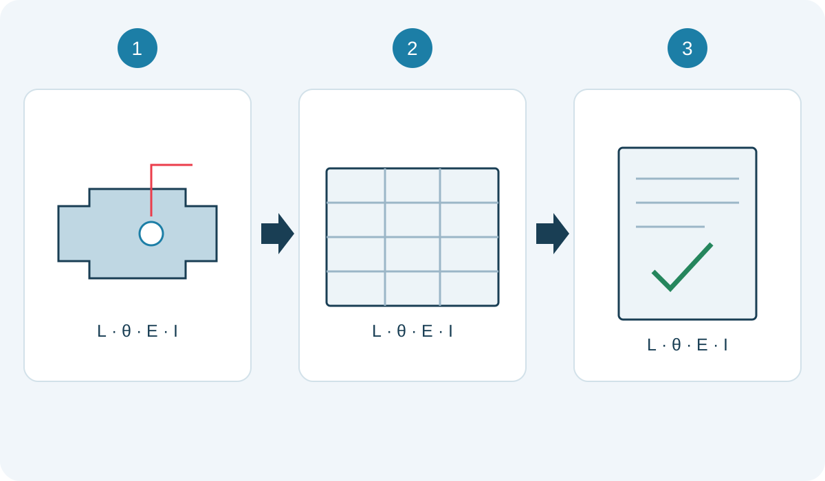
The table is a discussion template, not a mandatory test plan or a promise of included capabilities. Replace the descriptions with approved order-specific instructions. Resolve missing information before committing to production, and keep any proposed alternative distinct from the required drawing. A short, clear hole detail can prevent more uncertainty than an extensive inspection report written after the relevant surfaces are no longer accessible.
| Review item | What to define | Evidence question |
|---|---|---|
| Function and path | Hole purpose, blind or through route, connected features | Does the section show the intended connection? |
| Size and condition | Final dimensions, finish and any thread requirement | Is the result for the delivered state? |
| Location and angle | References, axial position and indexing relationship | Which requirement controls the reported position? |
| Edges and cleanliness | Entry, exit, internal intersection and residue limits | What can the chosen check actually demonstrate? |
| Approval and records | Source revision, method, coverage and exclusions | Who authorizes any change or unresolved item? |
Before releasing the order, review the quotation against this checklist and identify the responsible party for any assembly or functional verification outside the manufacturer's scope. Keep the drawing revision control process connected to the hole detail. If a model and a PDF disagree, resolve the authority of the documents in writing; do not let the drilling setup decide which interpretation becomes the product.
For a custom shaft enquiry, send the complete drawing, relevant sections, mating information, quantity and required reports together. State any uncertainty as a question rather than embedding an unapproved assumption in the order. A well-defined cross hole is not simply a diameter on a cylinder: it is a controlled connection between location, orientation, material removal, internal condition and the evidence needed for acceptance.
Frequently Asked Questions
Does a through-hole callout define its angular relation to a keyway?
Not by itself. Define the relevant indexing feature and relationship when the application requires them.
Does an outer-edge photograph prove the internal intersection is deburred?
No. The internal edge needs its own agreed requirement and suitable evidence; the accessible entry is a different location.
Can the shop move the hole slightly to improve drilling access?
Only when the responsible authority approves any change to the controlled requirement before use. Manufacturability does not override the drawing.
Does a passing dimensional report prove fluid or fatigue performance?
No. Dimensional acceptance and application validation are different. Specify any separate performance test and responsibility explicitly.