
Shaft Thread Specifications: What OEM Buyers Should Define Before Ordering
A threaded shaft can pass a quick assembly check and still leave important requirements unresolved. The mating nut may start easily but stop before reaching its intended seat. A thread may be acceptable before coating but difficult to assemble after finishing. A measured outside diameter does not, by itself, establish that the complete thread meets its specified requirements.
For OEM buyers, the useful starting point is the assembled function. Identify what the thread retains, adjusts or drives. Then define the thread designation, usable length, nearby geometry, final delivery condition and acceptance evidence around that function.
This guide focuses on requirements for custom shaft drawings. It does not prescribe a universal thread class, engagement length or tightening torque. Those decisions depend on the actual assembly, loading, materials and governing standards.
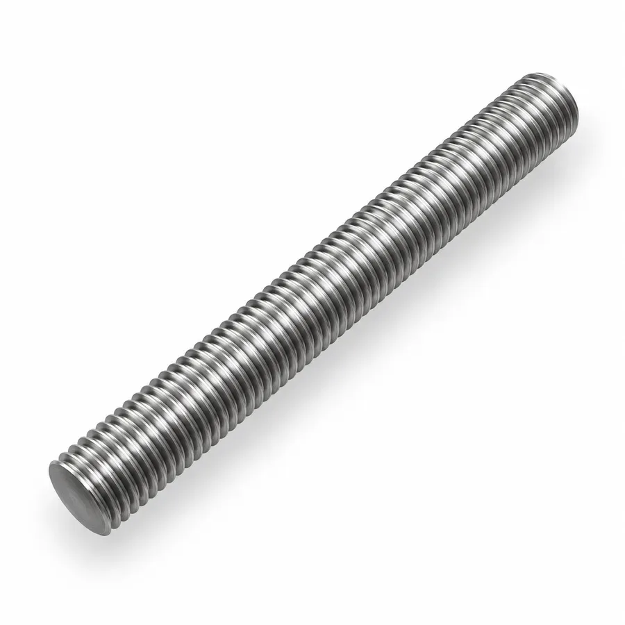
Product illustration selected from the existing website library. It illustrates a shaft form, not a specified thread standard or evidence of a particular manufactured order.
1. Define What the Thread Does
A retaining thread, an adjustment thread and a motion-transmission thread can require different design decisions. A thread used to hold a bearing arrangement against a shoulder is not automatically specified like a lead screw that repeatedly moves a carriage.
Describe the mating component and its purpose. State whether the joint is assembled once, serviced periodically or adjusted during operation. Identify requirements for locking, lubrication or assembly access when they affect the supplied shaft. Do not leave the supplier to infer these conditions from a generic product photograph.
Keep structural design responsibility clear. The designer must establish that the selected thread and mating materials are suitable for the applied loads. A supplier can review manufacturability and inspection access, but that review does not replace assembly strength calculations or validation.
For product context, see the threaded shaft product page. Use the actual drawing and mating-part information when requesting an assessment.
2. Give a Complete Thread Designation
An outside diameter alone is not a thread specification. Define the thread system and applicable standard, nominal size, pitch or threads per inch, and the required tolerance class. Identify internal versus external features and specify a left-hand thread when required.
Do not assume that similarly sized metric and inch threads are interchangeable. Likewise, a familiar nominal size does not establish every fit requirement. Keep the terminology consistent with the chosen standard rather than combining class designations from different thread systems.
If the assembly uses a special profile, multiple starts or a nonstandard requirement, provide the necessary definition and acceptance criteria. A standard fastener-thread callout should not stand in for a custom motion-thread specification.
Sandvik Coromant's Threading Application Guide distinguishes thread forms, tolerance classes and manufacturing approaches. For procurement, the practical lesson is to establish the required thread before choosing or approving a machining route.
3. Separate Full-Form Length from Overall Threaded Length
The axial region containing usable, complete thread forms may be shorter than the visually threaded region. Entry chamfers and incomplete threads near a shoulder can reduce the length available for engagement. A single length dimension can be ambiguous if the drawing does not define its endpoints and intended meaning.
Specify the required full-form length and its axial location. Show the entry condition, the transition at the other end, and any permitted incomplete-thread region. Define whether the mating component must reach a shoulder, stop at a separate feature or remain within an adjustment range.
Avoid choosing an arbitrary engagement length from a generic rule. Required engagement depends on the thread form, materials, joint loading and design acceptance criteria. The designer should establish that requirement; the supplier should confirm whether the drawing can be manufactured and inspected as specified.
A section or enlarged detail often communicates these relationships more clearly than a note saying only “thread to shoulder.”
4. Check Shoulder Clearance and Assembly Access
A correctly designated thread can still create an assembly problem if the adjacent shoulder, relief or mating-part chamfer is incompatible. The nut or internally threaded component may contact an incomplete thread or transition before reaching its intended seating face.
Review the shaft and mating component together. Define the shoulder position, available seating face and any clearance feature required by the assembly. Where a relief is necessary, specify its geometry rather than allowing an uncontrolled groove to be added during machining.
A relief also changes the local shaft section. Its dimensions and transition radii should be approved with the actual loading and fatigue requirements in mind. More clearance is not automatically better.
Check installation and removal space as well. Confirm whether a wrench, socket or other assembly tool can reach the component without damaging nearby surfaces. For other end-interface considerations, see the shaft end specification guide.
5. Define the Relationship to Functional Shaft Features
Thread acceptance and shaft geometry are related but separate questions. A thread may meet its specified size and fit requirements while a nearby bearing journal, shoulder face or other functional feature fails its own requirement.
Identify the functional datums and define the necessary relationships using the drawing's governing geometrical specification standard. Specify what feature is controlled and how the requirement relates to the assembly. Do not rely on a general instruction such as “keep the thread perfectly concentric.”
If rotational behavior matters, clarify which feature establishes the reference and which surface or derived feature is evaluated. Measuring a thread crest does not automatically establish the position or behavior of every other thread feature.
Agree on an achievable verification method before ordering. The shaft runout guide explains why datum selection, setup and measurement coverage belong in the specification discussion rather than being assumed from a single indicator reading.

Conceptual machining illustration from the existing website library. It is not a photograph documenting TOPSHAFT equipment, production conditions or a validated machining process.
6. Specify the Final Delivery Condition
State whether the thread is accepted before or after coating, heat treatment or another specified process. Treatments can affect dimensions, surface condition and the sequence needed to achieve the final requirements. The finished component, not an intermediate stage, must satisfy the agreed delivery specification.
For a coated thread, identify the coating requirement and any masking restrictions. Review the allowance and acceptance approach with the supplier. Do not prescribe a generic allowance without considering the coating, thread system and applicable requirements.
If heat treatment is required, clarify the final material condition and whether subsequent thread finishing is permitted or necessary. Do not assume that every thread will be cut, rolled or finished at the same stage of manufacture.
Record approved process exceptions in the quotation or order review. An informal statement that a mating nut “should still fit” is not an adequate replacement for the drawing's final-condition acceptance criteria. See the shaft heat-treatment specification guide for related requirements.
7. Control Entry Damage, Burrs and Cleanliness
The thread entrance is vulnerable during handling and assembly. A damaged first thread can prevent a satisfactory joint from starting correctly. Residual burrs or chips can also interfere with assembly or contaminate equipment.
Specify the required entry condition and edge treatment without allowing uncontrolled removal of functional thread material. Distinguish permissible edge finishing from damage, missing thread forms or alteration of the specified engagement region.
Keep cleanliness requirements separate from dimensional requirements. A shaft can be dimensionally acceptable and still contain contamination that is unacceptable for its application. Define relevant restrictions on chips, residues or protective products when needed.
For shipping, consider protection that prevents thread-to-thread or thread-to-hard-surface contact. Confirm compatibility with the assembly and cleaning process. The shaft deburring guide provides a framework for making edge requirements inspectable rather than relying on an undefined “burr-free” statement.
8. Agree on Inspection Coverage Before Production
Choose inspection around the specified thread and the acceptance question. A caliper or outside micrometer reading alone does not establish complete thread conformity. A pitch-identification tool does not provide the same evidence as the applicable acceptance inspection.
Where limit gauging is specified, agree on the appropriate gauge type, standard, identification and use conditions. Interpret GO and NOT GO results according to the applicable gauging rules, not a universal rule invented for every thread system. A successful check with an ordinary mating nut is not automatically equivalent to formal acceptance with the specified gauge.
Additional measurement may be needed for separately controlled dimensions or geometric relationships. Establish which checks are performed, at what manufacturing stage, and over what accessible regions. A gauge result should not be reported as proof of unrelated shoulder position, journal geometry or material properties.
For records, request the drawing revision, thread identification, agreed inspection method, instrument or gauge identification, sampling scope and disposition of exceptions. First-article evidence and routine production sampling may differ; settle both before order acceptance.

Conceptual inspection illustration from the existing website library. The pictured tool has no verified standard, size or calibration identity; the image does not demonstrate a conforming gauge check or inspection result.
9. Review the Quotation Against a Thread Checklist
Before placing the order, confirm that the quotation addresses the drawing rather than a simplified description such as “shaft with threaded end.” Resolve departures explicitly and retain the approved revision with the purchase order.
- Thread system, governing standard and complete designation.
- Required full-form length, axial location and permitted transitions.
- Mating-part information and functional seating requirements.
- Shoulder, entry and relief geometry.
- Functional datums and separately controlled relationships.
- Material condition, coating and final acceptance stage.
- Edge quality, cleanliness and transport protection.
- Inspection method, sampling and required records.
- Quantity, drawing revision and any approved exceptions.
When requirements are uncertain, identify them as open questions rather than silently selecting a supplier default. This makes competing quotations easier to compare and reduces the risk that a cheaper offer excludes necessary finishing or verification. The broader precision shaft RFQ checklist covers the remaining purchasing information.
10. Keep Changes and Acceptance Decisions Traceable
Thread requirements sometimes change after the first quotation. A different nut, revised coating or relocated shoulder can affect the agreed manufacturing route and inspection plan. Treat these changes as drawing revisions, not informal instructions that exist only in an email conversation.
Ask the supplier to identify which revision the quotation covers. Before production, reconcile the purchase order, drawing, any model and the agreed inspection requirements. If a model and drawing conflict, establish the controlling definition and resolve the discrepancy rather than leaving the machine operator to choose.
For first articles, distinguish a dimensional report from an assembly evaluation. Record whether the actual mating component was used, what condition it was in and what the trial assessed. A successful trial may provide useful assembly information, but it does not demonstrate fatigue life, retention under vibration or every requirement of the complete joint.
If a nonconformity occurs, document the affected characteristic and obtain an authorized disposition. Do not silently enlarge the mating part, recut the thread or remove coating to make an assembly trial pass. Those actions may change the approved interface and require a design review. Clear records help both buyer and supplier understand what was accepted and which requirements remain unchanged for repeat orders.
Frequently Asked Questions
Is nominal diameter enough to order a threaded shaft?
No. Provide a complete thread designation and the functional geometry around it. Diameter alone does not identify the thread system, pitch, required fit or usable engagement length.
Can a production nut replace a thread gauge?
A mating component can support an agreed assembly trial, but it does not automatically replace the specified gauging or measurement method. Define the purpose and acceptance criteria of each check.
Should every threaded shaft use the tightest tolerance class?
No. Select requirements for the actual function and standard. Unnecessary precision can increase manufacturing and inspection effort without resolving an incorrectly defined assembly interface.
Does thread gauging prove the whole shaft is acceptable?
No. Journals, shoulders, geometry, materials and surface requirements need their own agreed verification. Report thread acceptance only within the scope of the inspection performed.
Should the thread be inspected before or after coating?
Define final acceptance for the specified delivery condition. In-process checks can be useful, but they do not substitute for confirming requirements that apply after the final treatment.
Request a Drawing-Based Thread Review
Send TOPSHAFT your shaft drawing, quantity, material requirement and relevant mating-part information. Highlight the thread function, critical seating features, final surface condition and inspection records required with delivery.
TOPSHAFT can review the requested project and clarify manufacturing and inspection requirements during quotation. Specific processes, tolerances, gauges and documentation must be confirmed for the actual component; they should not be inferred from illustrative images. Share your requirements with TOPSHAFT to begin the review.