
Shaft Deburring Requirements: How OEM Buyers Should Specify Edge Quality
A shaft can pass its diameter inspection and still cause an assembly problem. A small burr on a keyway can obstruct a key. A damaged thread entrance can make a nut difficult to start. Loose material inside an oil passage can become contamination after the shaft enters service.
These problems are easy to overlook when a drawing focuses on diameters, fits and surface finish. A general instruction to remove burrs is useful, but it does not always explain which edges must remain sharp, how much material may be removed or how hidden intersections will be checked.
Your goal is not to make every edge look rounded. It is to remove unwanted material while preserving the geometry that supports assembly and operation. For OEM buyers, a clear edge-quality requirement connects the drawing, manufacturing route and inspection plan before production starts.
1. Start With the Function of Each Edge
Before writing a deburring note, identify what each edge does. A bearing-entry edge may help a mating part slide into position. A retaining-ring groove edge helps define the seating geometry. A spline entrance supports engagement, while an oil-hole outlet connects a passage to a lubricated surface.
Those edges do not necessarily need the same treatment. An edge that is safe to round on one shaft may need tightly controlled geometry on another. A larger edge break can improve handling but also reduce usable contact length or change an adjacent feature.
Review the shaft with the assembly in mind. Ask where a component first contacts the shaft, where a seal passes over an opening and where debris could remain trapped. Mark the edges whose condition directly affects those interactions.
This review belongs alongside your bearing-journal specification, not after the diameter tolerances have already been finalized. Dimensions and edge condition should describe the same functional part.
2. Separate Burr Removal From Chamfering
A burr is unwanted material associated with machining. A chamfer or radius is an intentional geometric feature. Removing a burr does not automatically authorize the supplier to add a large chamfer, blend a shoulder or round a groove edge.
The distinction matters when you inspect the result. A visibly smooth edge could still be unacceptable if excessive material removal changes the feature. Conversely, a controlled edge that is not visibly rounded may satisfy the drawing if unwanted material has been removed.
ISO 13715 addresses the indication and dimensioning of edges of undefined shape. Its public description distinguishes those edges from a specifically defined geometry, such as a dimensioned chamfer. Where you require a particular shape, specify that shape explicitly rather than relying on a vague finishing instruction.
Do not introduce a universal chamfer size simply because it is convenient. The correct allowance depends on the surrounding geometry, material and assembly. Confirm critical values with the responsible design engineer.
3. Identify the Shaft Features Most Likely to Need Attention
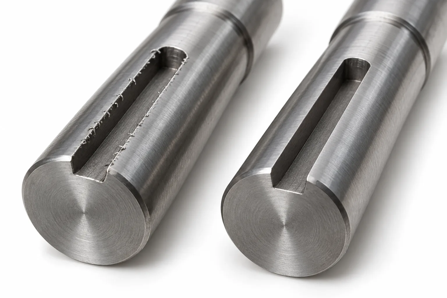
AI-generated illustration: burr removal should preserve the specified keyway geometry.
Keyways deserve attention along their side edges, ends and transitions. Burrs can interfere with key installation or create loose fragments during assembly. Excessive blending, however, can change the intended seating geometry. Keep edge treatment consistent with your keyway requirements.
For splines, review the entrance and the boundaries of the working tooth surfaces. The deburring process should not unintentionally alter the specified profile or fit. For threads, consider both the start and the exit of the threaded section, including the relationship with any relief groove.
Cross-drilled holes have entry and exit edges, and may also intersect another passage inside the shaft. The visible outer opening does not tell you whether the internal intersection has been treated.
Grooves and shoulders need a similar functional review. A groove used for a retaining ring or seal should retain its defined width, depth and edge geometry. Inspect the complete feature rather than judging only whether it feels smooth.
4. Write a Drawing Requirement That Can Be Inspected
A useful requirement identifies the applicable edges, the permitted result and the exceptions. Separate general handling edges from the edges whose geometry must be individually controlled. Avoid leaving two contradictory instructions on the same drawing.
For example, a general burr-removal note can be accompanied by specific callouts for a thread entrance, seal-crossing hole or functional groove. The individual requirements should take precedence where the drawing says they do. Make that hierarchy clear during drawing review.
Define any allowed edge break through the approved drawing system. If an edge must retain its shape within a specified limit, identify the limit and the inspection approach. Do not substitute a photograph for the dimensions that govern functional geometry.
You can use an agreed reference sample or photographs to support interpretation of appearance, especially where terminology has caused disagreement. Identify what the reference demonstrates and what still remains controlled by the drawing. A reference should clarify acceptance, not quietly replace engineering requirements.
5. Treat Internal Intersections as a Separate Inspection Problem
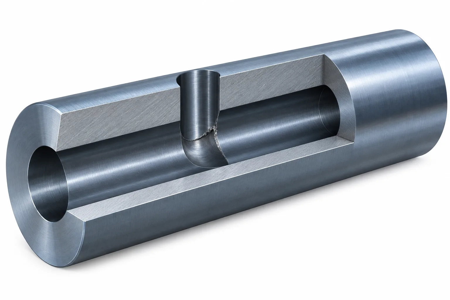
AI-generated cutaway illustration; passage geometry is schematic and not dimensioned.
An internal burr can be difficult to reach and difficult to observe. When an axial bore meets a radial hole, the intersection is a separate location from the hole openings. Include it explicitly in the manufacturing and inspection discussion.
Purpose-designed tools exist for internal intersections. For example, NOGA's cross-hole brush guidance describes tools that contact internal bores and cross-hole edges. That establishes an available process category; it does not prove that a particular tool will suit your shaft or meet its acceptance criteria.
Selection still depends on access, passage dimensions, material and the amount of unwanted material. Ask the supplier how it will reach the intersection and how it will verify the result without damaging the bore.
Where direct inspection is possible, an appropriate borescope or other agreed method may help. Where visibility is limited, discuss how the process will be qualified and what evidence will support acceptance. Do not treat a clean-looking outer hole as proof of an acceptable internal edge.
6. Choose the Process Around the Required Result
Manual deburring, controlled cutting and abrasive finishing can address different geometries. No single approach is automatically best for every shaft. Accessibility, production quantity, material condition and the risk of changing functional surfaces all influence the choice.
For a prototype, a carefully controlled manual operation may be practical. For repeat production, the supplier may consider a more repeatable machine-based route. In either case, agree on the acceptable result rather than prescribing a process that has not been reviewed for the actual part.
Ask how tool wear, access and operator judgment will be controlled. A process that works on the first sample may need adjustments as tools wear or as incoming burr conditions vary. This is particularly important when the allowable edge change is small.
Your CNC turning and feature-machining review should therefore include deburring access. It is better to resolve an inaccessible intersection while planning the machining route than to discover it at final inspection.
7. Place Deburring and Cleaning in the Manufacturing Sequence
An early deburring operation does not guarantee that the delivered shaft is acceptable. Later drilling, milling or thread machining can introduce new burrs. Review the last material-removal operation affecting each critical edge.
Consider whether heat treatment, coating or final grinding changes the practical sequence. The aim is to deliver the specified geometry and cleanliness in the final condition, not merely to document that a deburring operation occurred at some earlier stage.
Cleaning is a separate requirement. Burr removal may release particles, and some finishing methods can leave residues. Define the final cleaning expectation according to the assembly and service conditions. Do not assume that a part described as deburred has also been cleaned to an agreed cleanliness level.
Where cleanliness limits are necessary, specify the applicable procedure and acceptance criteria through the approved project documents. Avoid unsupported promises such as completely particle-free. Confirm how the part will be protected after cleaning and before packing.
8. Protect Journals, Datums and Finished Surfaces
Deburring should not become a source of new damage. The shaft may need protection against scratches, dents or uncontrolled abrasion on bearing journals, seal-running surfaces and locating datums.
Discuss workholding and handling. A shaft secured for edge finishing should remain supported without marking critical surfaces. When an abrasive process is proposed, ask which surfaces will be contacted and which need protection or subsequent verification.
Inspect adjacent geometry after treatment where the operation can affect it. Checking only the edge appearance can miss damage to a nearby journal or changes to a functional groove. Connect the edge inspection with the relevant dimensional checks.
For sealing surfaces, use your seal-journal requirements and surface-finish specification together. A smooth edge does not compensate for a scratched running surface or an incorrect final dimension.
9. Agree on Inspection Before Approving Production
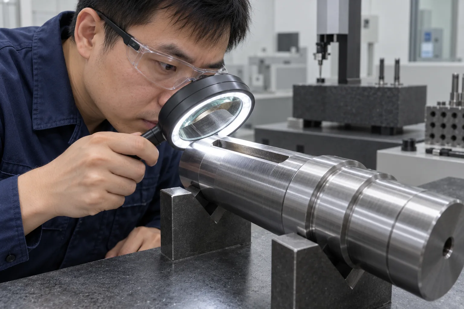
AI-generated inspection illustration, not a photograph of a TOPSHAFT employee or facility.
Start with a location-based inspection plan. List the edges that require verification and distinguish accessible external features from hidden internal intersections. This prevents an inspector from checking only the easiest locations.
Where appearance is part of acceptance, agree on viewing conditions and any required magnification. State whether photographs or inspection records are needed. Different lighting and viewing angles can make the same small edge look very different.
Do not use bare-finger checks as the sole acceptance method. They are subjective and can expose the inspector to sharp edges. Choose a method appropriate to the requirement and the risk.
Also agree on sampling and escalation. Decide which characteristics need individual checks and which can be sampled under the approved quality plan. If a problem is found, define how affected parts will be contained, reworked and reinspected. TOPSHAFT's Inspection & Quality page provides the drawing-based context for that discussion; project-specific methods still need confirmation.
10. Include Edge Quality in Your Shaft RFQ
Your request for quotation should include the current drawing revision and identify edge requirements that are especially important to assembly or cleanliness. Call out internal passages rather than expecting the supplier to infer their function.
Provide the material, treatment condition and production quantity. Explain whether the shaft will carry seals, bearings, splines or threaded mating parts across the edges in question. Include any approved reference images, cleanliness procedure or required inspection records.
Ask the supplier to flag unclear requirements before quotation. A question about an edge allowance is more useful than an assumption that later becomes a rejection. Resolve whether the proposed process can access the feature, preserve the geometry and support the agreed inspection.
For custom shaft projects, share the complete part rather than an isolated edge detail. The surrounding features often determine how the shaft can be held, machined, cleaned and inspected.
Frequently Asked Questions
Is a general remove-burrs note enough?
It may be sufficient for some noncritical edges, but it does not fully describe controlled edge geometry or hidden intersections. Add specific requirements where assembly, sealing or cleanliness depends on the result.
Does every deburred edge need a chamfer?
No. A chamfer is a defined geometric feature. Burr removal must remain within the approved edge requirements and should not introduce an unrequested shape.
Can a visual check confirm internal burr removal?
Only where the relevant intersection can actually be viewed using an appropriate method. Visibility at the outside opening does not establish the condition deeper inside the shaft.
Should I specify the exact deburring tool?
Usually, define the required result first and review the proposed process with the supplier. Specify a tool or method only where the project requires it and its suitability has been established.
Are deburring and cleaning the same requirement?
No. Deburring addresses unwanted edge material. Cleaning addresses particles and residues. Specify both where the application needs them.
What should accompany a deburring-related quotation request?
Include the drawing revision, material, critical edge locations, permitted geometry changes, internal-passage details, quantity and inspection expectations. Add the cleanliness requirements where applicable.
Request a Drawing-Based Review
Send your shaft drawing and identify the edges that affect assembly, sealing or cleanliness. TOPSHAFT can review the requirements with the proposed manufacturing route; specific processes and acceptance methods should be confirmed for the individual project.
Submit your drawing for review.
Images accompanying this article are AI-generated technical illustrations, not photographs of TOPSHAFT facilities or inspection records. Illustrations do not define dimensions or acceptance criteria.