
Hollow Shaft Bore Specifications: What OEM Buyers Should Define Before Ordering
A hollow shaft needs more than an outside diameter and a bore size. Its internal geometry can affect assembly, remaining wall thickness, cleaning and inspection. A shaft may meet its bore diameter requirement at the entrance while leaving other functional requirements unverified.
For OEM buyers, the first question is what the bore must do. Is it a passage, a clearance space, or a precision interface for another component? That answer determines which dimensions, surfaces and geometric relationships need control. It also prevents unnecessary finishing on surfaces that have no precision function.
Prepare the specification around the final component, not an assumed machining method. Define the relevant features and acceptance evidence, then review the manufacturing route with the supplier. This guide explains the decisions to make before releasing a hollow shaft drawing for quotation.
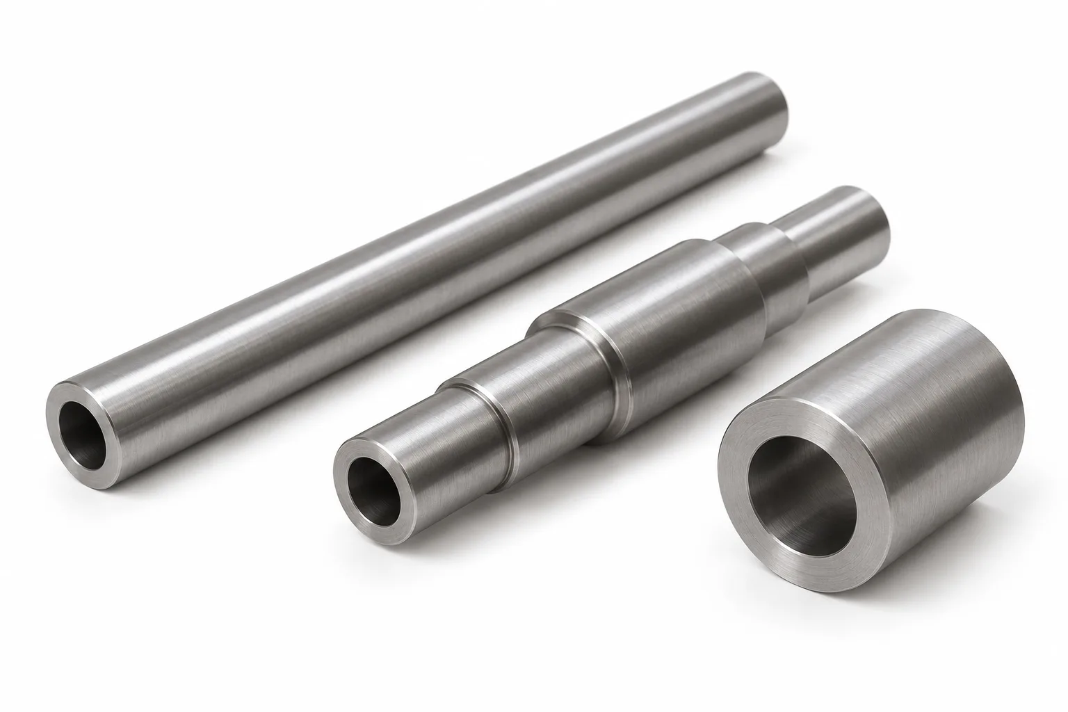
AI-generated product illustration. The parts are conceptual examples, not photographs of actual TOPSHAFT deliveries.
1. Start With the Bore's Function
A weight-reduction bore and a precision mating bore need different controls. For a clearance passage, the important questions may be minimum usable opening, internal obstructions and cleanliness. For a mating component, diameter, fit length, surface condition and the bore's relationship to the external journals may all matter.
Describe the application without assuming the supplier has access to your assembly model. Identify what passes through the bore, where it contacts the shaft, and whether the bore carries fluid or contains a moving component. State any restrictions on internal steps or interruptions.
Do not specify a tight tolerance along the entire bore simply because one end locates a mating part. Define the functional region separately. A short precision seat and a longer clearance passage can be specified differently if the design permits it. See the hollow shaft product page for the relevant product family, then send the actual drawing for review.
2. Show the Complete Internal Geometry
Use an appropriate section view to show features that an external view cannot explain. Identify whether the hole is through or blind. For a blind bore, distinguish usable cylindrical depth from total depth including the drill-point region, where relevant.
Dimension counterbores, internal shoulders, reliefs and lead-in chamfers. Locate cross-holes from the specified references. If internal threads are present, define the thread specification, usable engagement length and any required clearance beyond the thread. Do not leave these details to a generic note saying “bore as model.”
Check that the drawing and model agree. A model may show a nominal sharp corner while the drawing allows a tool radius. Resolve conflicts before the purchase order, including which document governs acceptance. Avoid adding details merely because they look complete; each requirement should support the intended function or an agreed manufacturing allowance.
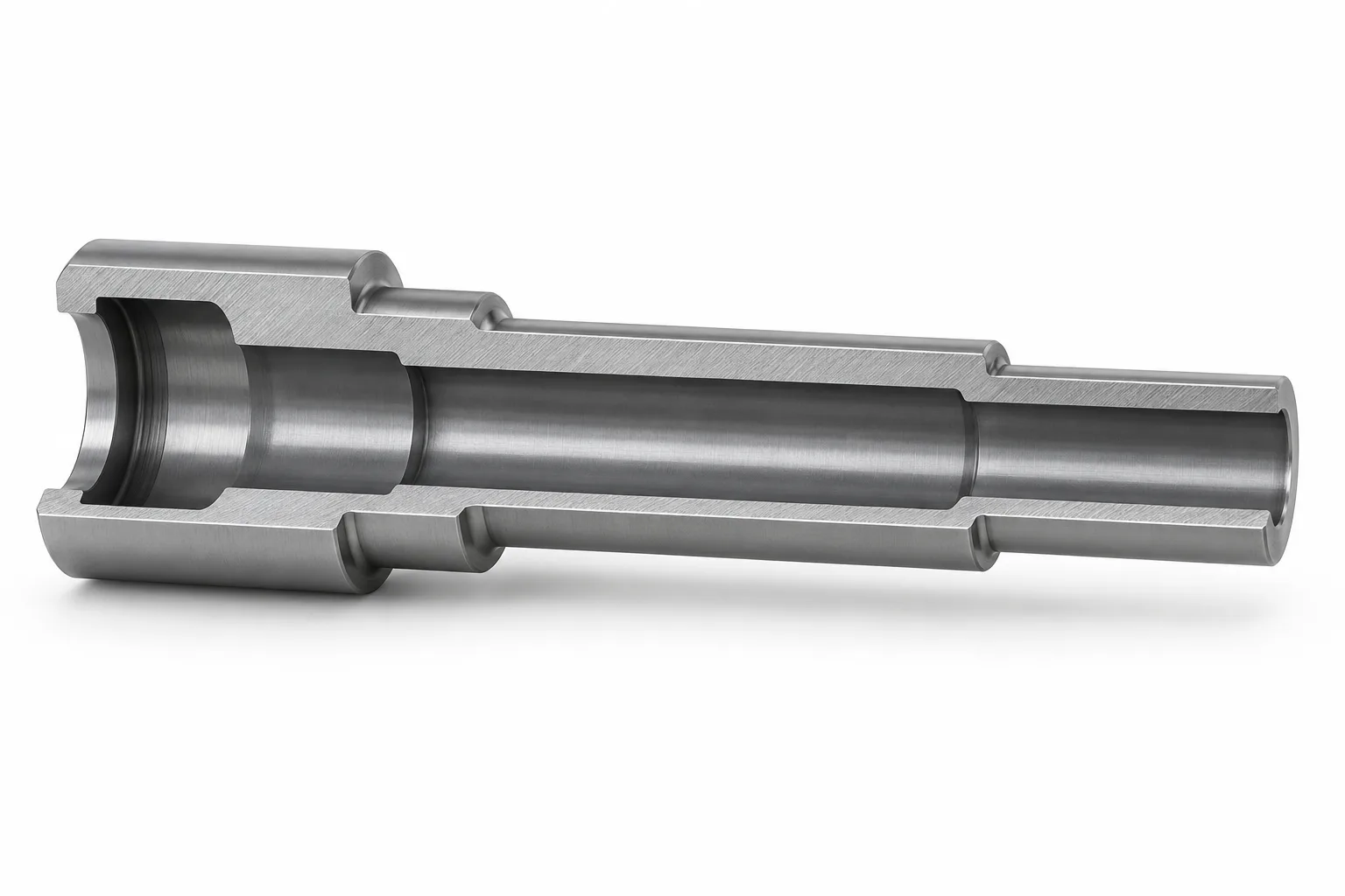
AI-generated conceptual cutaway. It illustrates internal features and wall sections; it is not a dimensioned drawing or an approved component design.
3. Separate Bore Size From Geometric Relationships
Diameter does not describe every aspect of a bore. Measurements at selected sections can show size at those locations, but they do not automatically establish the bore's axis relative to the bearing journals. Likewise, an external runout report does not prove that the internal geometry meets its requirements.
If the relationship matters, the responsible designer should select suitable geometric controls and datums under the drawing's stated standard. Define which external features establish the functional reference, which internal feature is controlled, and the extent over which the requirement applies.
Avoid an unexplained instruction such as “perfectly concentric.” Different geometric requirements assess different characteristics. They also require different measurement approaches. A supplier should not have to infer the intended acceptance test from informal wording.
Review the shaft runout specification guide alongside the bore requirements. Keep component geometry separate from installed machine alignment: passing either inspection does not establish the other.
4. Review Remaining Wall Thickness
The smallest wall section may occur beside an external keyway, thread root, groove or cross-hole rather than along the plain shaft body. Review the complete feature combination. A nominal outside diameter minus a nominal bore diameter is not enough when the local geometry is interrupted.
For an ideal circular concentric section, nominal radial wall thickness is half the difference between outside and inside diameters. That calculation alone does not establish the minimum wall on a finished component. Dimensional variation, axis displacement and local material removal must be considered where they affect the design.
Ask the engineering team to identify critical sections and decide whether a minimum-wall requirement is necessary. The design review should consider the actual loading and environment; no universal wall thickness is proposed here.
If wall thickness is an acceptance characteristic, agree how and where it will be verified. Do not assume that separate diameter measurements demonstrate the local minimum. Record any inspection limitations before quoting rather than discovering them during final acceptance.
5. Apply Internal Surface Requirements Where They Matter
Specify internal surface condition according to its function. A mating seat may need a defined roughness requirement, while a clearance passage may primarily need freedom from unacceptable obstructions and damage. A fluid passage may introduce separate cleanliness or application requirements.
Define the surface region covered by a roughness callout. Identify the parameter and limit under the applicable drawing standard, and discuss measurement access when the surface is deep inside the shaft. Do not assume that an instrument used on the external journal can reach the required internal location.
A polished-looking surface is not evidence of a measured roughness value. Similarly, a borescope image does not establish a surface roughness result. Where numerical verification is required, agree the method and reporting scope.
The shaft surface finish guide can help structure these requirements. Apply it to the actual internal surface rather than copying every external callout into the bore.
6. Review the Manufacturing Route During Quotation
A hollow shaft may start from suitable hollow stock or from solid material with a machined bore. The appropriate route depends on material, geometry, quantity, available stock and final requirements. Do not assume that either starting form automatically satisfies precision internal features.
Review bore length and diameter together. Tool access, chip evacuation, internal steps and cross-hole interruptions can affect process planning. Sandvik Coromant's deep-hole drilling product information identifies application-specific tooling for deep holes; it is not a capability guarantee for your supplier or a tolerance recommendation for your part.
Also separate generating the hole from finishing its functional surfaces. Additional operations may be needed, depending on the drawing. Sandvik Coromant discusses drilling and subsequent reaming in its holemaking technical session. Any proposed process still needs review against your material, features and acceptance criteria.
Request a drawing-based feasibility review before specifying a process as mandatory. If a particular route is essential for design reasons, explain those reasons and define the evidence needed to confirm compliance.
7. Address Internal Burrs and Cleaning
Cross-hole intersections, bore exits and threaded transitions deserve explicit attention. A burr may be hidden inside the shaft even when the external edges appear satisfactory. Identify the regions where loose material or protruding edges would interfere with the application.
Use inspectable requirements. A broad instruction such as “completely burr-free” leaves uncertainty about allowable edge condition and the method used to assess it. Where a controlled edge break is needed, specify the permitted condition without unintentionally changing a functional seat or sealing edge.
Define cleanliness separately from dimensional acceptance. State any application-specific contamination limits, cleaning restrictions or approved acceptance procedure. Do not assume that blowing air through the bore proves compliance with a defined cleanliness requirement.
If protective oil is used, confirm its compatibility with the next assembly step. Specify whether the bore is delivered protected, dry or prepared for a particular downstream operation. The shaft deburring guide provides related drawing-review questions, but the internal intersections still need their own inspection plan.
8. Agree on Inspection Coverage Before Ordering
An inspection method must demonstrate the characteristic being accepted. A bore gauge can assess diameter at accessible measurement positions. An end-only reading does not establish every section along a long bore, nor does it establish the bore's axis relative to external datums.
Ask the supplier to identify measurement locations, accessible depth, instrument type, setup and record format. Where the requirement includes geometry or wall thickness, review a method appropriate to that characteristic. Tool reach, bore size and feature interruptions may limit what can be measured directly.
A borescope can support visual examination of internal surfaces and intersections. It does not, by itself, provide dimensional, wall-thickness or roughness verification. Separate visual observations from numerical acceptance results in the report.
Agree whether reports are required for each part, selected samples or a first-article review. Identify drawing revision, part or batch identity, units and acceptance limits. If complete verification is not feasible with the proposed method, resolve that limitation before accepting the quotation.
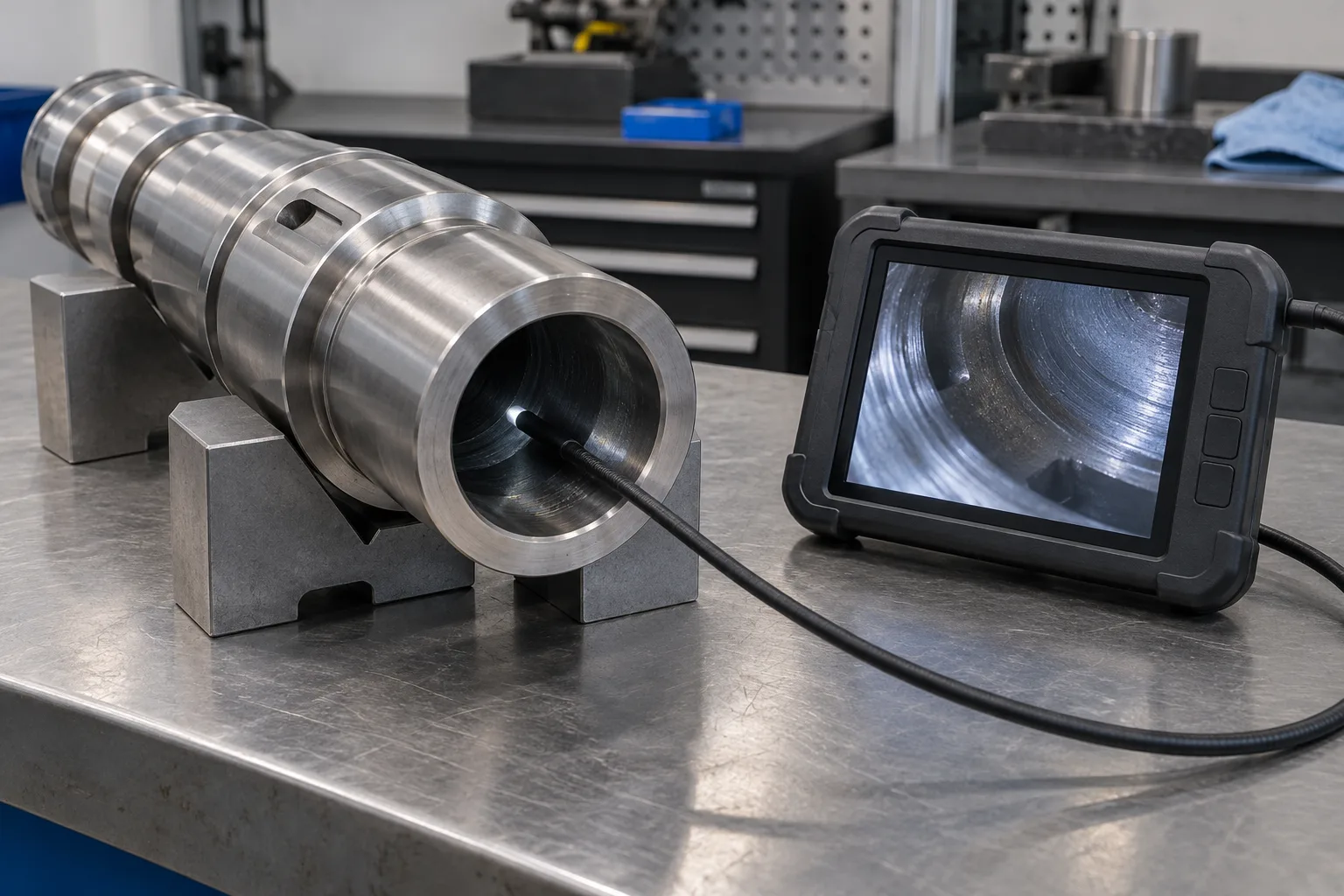
AI-generated visual-inspection illustration. A videoscope view is not a dimensional measurement, and this image is not an actual TOPSHAFT inspection record.
9. Define the Final Delivery Condition
Heat treatment, coating and subsequent finishing can affect the manufacturing sequence. State which bore dimensions and geometric requirements apply to the final delivered condition. Do not leave a supplier to decide whether a tight tolerance is measured before or after treatment.
Identify internal surfaces that require treatment or must be excluded from a coating. Discuss access and feasibility during quotation. Where post-treatment finishing is necessary, review the available machining allowance and which features establish the finishing references.
Avoid assuming that an external hardness measurement establishes the condition of every internal surface. If the application requires a particular internal material condition, the designer should define it and agree appropriate evidence with the supplier.
Use the shaft heat-treatment specification guide to organize the requirements. Keep material certificates, treatment records and final dimensional reports distinct so each document demonstrates its intended characteristic.
10. Hollow Shaft RFQ Checklist
Before requesting a quotation, confirm that the package includes:
- The current drawing revision and matching model, with document priority defined.
- Bore function, through or blind geometry, usable depth and internal transitions.
- Functional fit regions and any separate clearance regions.
- Required relationships between the bore and external functional datums.
- Critical wall sections and any approved minimum-wall requirements.
- Internal surface, edge-condition and cleanliness requirements.
- Material, treatment and final delivery condition.
- Inspection characteristics, measurement coverage and reporting expectations.
- Quantity, prototype or production stage, and relevant assembly context.
Use the precision shaft RFQ checklist for the wider procurement package. Identify unresolved engineering decisions rather than replacing them with unnecessarily tight general tolerances.
Frequently Asked Questions
Does a correct bore diameter prove uniform wall thickness?
No. Separate diameter measurements do not necessarily establish axis displacement or local wall thickness beside interrupted features. Define and verify the characteristic the design actually needs.
Must every hollow shaft bore be precision-finished?
No. Apply finishing requirements to the bore's function. A clearance passage and a precision mating seat may need different controls, even within the same shaft.
Can a borescope replace bore measurement?
Not by itself. It can support visual inspection, but it does not establish diameter, geometry or roughness unless a separate validated measurement method is specified and agreed.
Is there one suitable bore tolerance for all hollow shafts?
No. Select requirements for the actual mating interface, operating conditions and drawing standard. The article does not prescribe a universal tolerance or wall thickness.
What should the supplier confirm before accepting the order?
The supplier should review the drawing, proposed route, final delivery condition and inspection scope. Any exceptions or inaccessible characteristics should be resolved before order acceptance, not hidden behind a general statement of compliance.
Request a Drawing-Based Review
Send TOPSHAFT your hollow shaft drawing, quantity, material requirements and assembly context. Identify the internal features that matter and the records you expect with delivery.
Ask for confirmation of manufacturing feasibility and inspection coverage during quotation. Specific processes, tolerances and documentation must be agreed for the actual part, not assumed from an illustrative product image. Share your requirements with TOPSHAFT to begin the review.