
Shaft Load Cases and Duty Cycles: What OEM Buyers Should Share Before Manufacturing
A shaft enquiry arrives with a motor power rating, an overall length and a request for a stronger material. Those inputs may start a discussion, but they do not define the loads acting on the finished component. A gear can introduce transverse forces, a belt can load an overhung section, and braking can reverse torque. The bearing arrangement determines how those actions reach the shaft. Two applications with the same nominal motor power can therefore require very different engineering reviews.
For OEM purchasing teams, the useful first step is not choosing a universal safety factor. It is describing the application consistently enough for the responsible engineer and manufacturer to understand the request. This guide explains a practical load-data package, the operating events it should cover and the boundaries between manufacturing review and design approval. It does not calculate a safe shaft diameter, establish fatigue life or claim that TOPSHAFT offers a particular analysis or testing capability.
1. State Who Owns the Design Decision
Identify whether the order is build-to-print, manufacture from a customer-approved model, or a request for engineering development. A manufacturing quotation can confirm a proposed process and inspection scope without validating the component for service. Record who approves geometry, material condition, load assumptions and operating limits. Where the application requires specialist design assessment, arrange that assessment explicitly rather than assuming it is included in a machining price.
Send the released drawing and its revision together with the application information. Mark preliminary dimensions and unconfirmed loads as provisional. A supplier should not have to guess whether a feature is mandatory or an illustration of a possible solution. The shaft RFQ checklist helps organize manufacturing inputs; the load package adds the service context needed to discuss those inputs responsibly.
2. Draw the Load Path and Support Arrangement
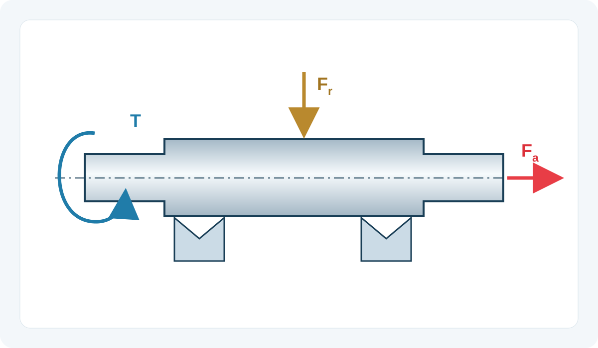
Provide a simple assembly sketch showing the shaft, bearing locations, gears, pulleys, couplings and axial stops. Identify where each force or torque enters and leaves the component. Give axial positions or distances from a clearly named reference, and explain which parts move during operation. An overhung pulley and a pulley between two bearings do not create the same bending situation merely because their belt force has the same magnitude.
Describe the actual bearing and housing arrangement, including which locations locate axially and which permit intended movement. Do not describe supports as perfectly rigid unless that is an approved modelling assumption. Housing flexibility, assembly clearance and contact conditions can matter. Explain what is known and what remains to be determined; a clean sketch with explicit unknowns is more useful than a detailed model whose support assumptions are hidden.
3. Separate Torque, Forces and Moments
List transmitted torque, transverse or radial forces, axial thrust and externally applied moments separately. Include units and directions. A torque value in N·m is not interchangeable with a force in N, even though a force acting through a lever arm can produce a moment. Identify whether a stated moment is torsional about the shaft axis or a bending moment about a transverse axis.
Use a clear coordinate system and viewing direction. For example, define positive rotation as seen from the drive end, then use that convention throughout the load table. State whether values are measured, supplied by a component manufacturer, calculated by the customer or estimated. Do not present an estimate as a verified operating limit. If important data are missing, request clarification before selecting a grade or accepting a proposed manufacturing change.
4. Distinguish Normal Torque From Operating Peaks
A nominal power and speed can help describe a steady operating point, but they do not by themselves describe acceleration, braking, jams or drive-control limits. Ask for normal torque and relevant peak events separately, including duration, frequency and direction. Identify the shaft section to which the value applies, especially across gearing or other speed-changing elements. Do not transfer a motor-side value to the output shaft without considering the transmission.
Component selection guidance is application-specific. KTR's selection resources illustrate the use of product-specific selection guides and questionnaires. They are not a general shaft design standard. Do not copy a coupling service factor into a shaft calculation without a justified method, and do not assume a protective device eliminates every transient unless its actual behavior and settings have been established.
5. Describe Speed as a Range and an Event
Record normal speed, minimum and maximum intended speed, direction, acceleration and deceleration where relevant. Identify any overspeed event the responsible engineer requires the design to address. Distinguish continuous operation from a brief excursion and specify the units. A single maximum-speed number does not describe how long the machine operates there or what load is present at that time.
Explain whether speed passes repeatedly through particular operating regions and whether the assembly has known vibration restrictions. A diameter calculation alone does not resolve rotor dynamics, balance, bearing suitability or coupling selection. Those questions may need separate specialist review. The shaft balancing guide describes information needed for an agreed balancing scope; it does not establish that any shaft is suitable for an arbitrary rotational speed.
6. Make the Duty Cycle Specific
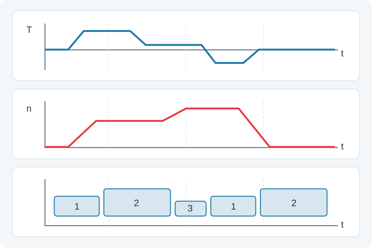
Describe the sequence of operation: start, accelerate, process, dwell, decelerate and stop, or the relevant sequence for the machine. Give the time or proportion associated with each state, the expected starts and stops, and the planned service duration. If the machine has several programs, identify the applicable operating mix rather than describing only the easiest demonstration cycle.
Keep operating hours, revolutions and load cycles distinct. Their relationship depends on how the loading changes relative to the rotating material and on events such as reversals. Do not treat one start as the only fatigue cycle or convert hours to a fatigue assessment without a defined loading model. The design authority should specify the relevant load history and assessment method; purchasing should preserve that information instead of reducing it to a vague heavy-duty label.
7. Identify Which Loads Occur Together
Create separate load cases for meaningful operating states and exceptional events. State which torque, radial force, axial force and speed values occur simultaneously. Simply combining every individual maximum can describe an event that never occurs, while using only average values can miss a real severe combination. Any deliberately conservative combination should be identified and approved, not hidden inside an unexplained spreadsheet.
For measured histories, retain the time relationship between channels and explain the measurement location, sampling limitations and processing used. For calculated inputs, retain their source and assumptions. If an exceptional jam cannot be described reliably, record that uncertainty and identify the required investigation. Avoid inventing a peak value merely to fill a table; uncertainty in the load definition should remain visible to the engineer making the decision.
8. Connect Loads With Geometry and Environment
Point out shoulders, grooves, keyways, splines, threads, cross-holes and diameter transitions in the loaded regions. Their position and geometry can affect the engineering assessment, but a feature name alone does not quantify its effect. Supply the actual drawing rather than a generic shaft outline. Surface condition, manufacturing sequence and material condition should be discussed in the context of the approved design, not as interchangeable routes to guaranteed strength.
Include temperature, corrosion exposure, lubrication where applicable and assembly constraints that may change the load or the required material condition. Distinguish service exposure from storage requirements. The material selection guide and shoulder and fillet guide provide related review questions. Neither justifies replacing a material, changing a fillet or tightening a tolerance without the necessary design approval.
9. Use a Load-Case Table in the RFQ
| Information | What to provide | What to avoid |
|---|---|---|
| State or event | Normal running, starting, braking or defined abnormal event | One unexplained maximum |
| Applied loads | Torque, forces, moments, units, directions and locations | Mixing force and torque units |
| Simultaneous conditions | Associated speed and loads occurring together | Combining unrelated peaks silently |
| Exposure | Duration, repetition and operating sequence | An undefined heavy-duty claim |
| Data confidence | Source, revision, assumptions and unresolved items | Treating estimates as verified limits |
Attach the table to the drawing package and keep its revision identifiable. State whether the figures define a design requirement, describe measured operation or provide preliminary background for a quotation. Those purposes are not equivalent. If different teams provide conflicting values, resolve ownership and the controlling version before purchase approval rather than asking the manufacturer to choose the most convenient set of numbers.
10. Agree What Evidence Will Demonstrate Acceptance
Separate dimensional acceptance from service-performance validation. A material certificate, a hardness result and a dimensional report each address particular requirements; together they do not automatically prove fatigue life or overload resistance. If functional testing is required, agree its objective, conditions, sample identification, acceptance criteria and responsibility in a specific plan. Do not invent a universal proof-load test for a finished shaft.
Connect the agreed evidence with the first-article approval process. Keep the approved drawing, load assumptions, manufacturing condition and inspection results traceable to the same revision. If an operating limit changes after approval, review its implications before assuming the existing part remains suitable. Successful delivery of a machined part and engineering validation of a complete assembly are different milestones, even when they share documentation.
11. A Practical Pre-Order Checklist
- Identify the design authority, released drawing and revision, and the boundary of the requested supplier scope.
- Provide bearing locations, overhangs, drive connections, axial stops and a readable load-path sketch.
- List torque, radial and axial forces, external moments, units, directions and application locations separately.
- Describe speed ranges, starts, stops, reversals, peaks and the conditions that occur simultaneously.
- Record event duration, repetition, operating mix and required service context without inventing missing values.
- Identify data sources, estimates, unresolved assumptions and the person responsible for confirming them.
- Agree manufacturing evidence, any separate validation plan and the approval route for later changes.
Use this checklist to improve the technical conversation, not as a substitute for a qualified design assessment. For a custom shaft enquiry, share the released drawing, quantity, material requirements and relevant application data. TOPSHAFT can review the manufacturing request and confirm the proposed scope during quotation. Any engineering analysis, test program or performance commitment must be expressly agreed; this article makes no general capability, certification or service-life claim.
FAQ
Is motor power enough to specify the shaft load?
No. Power and speed can describe a steady operating point, but the shaft may also experience transverse forces, axial thrust, starts, braking and abnormal events. Supply the load path and relevant operating cases.
Can I use the highest torque and highest speed as one case?
Only when that combination represents the required event or an explicitly approved conservative case. Identify simultaneous conditions instead of silently combining unrelated maxima.
Does a stronger material remove the need to describe duty?
No. Geometry, material condition, loading history, environment and design criteria still require review. A grade change is not automatic proof of acceptable fatigue life or assembly performance.
Does passing dimensional inspection validate service life?
No. It establishes conformity to the inspected requirements under the agreed method. Service-performance validation requires its own justified assessment and, where specified, an agreed test plan.