
Shaft Roundness and Cylindricity: Agree the Inspection Evidence
A shaft journal passes the recorded diameter checks, yet an engineer asks whether its roundness or cylindricity was verified. The inspection report contains several size readings and an indicator value, but no clear connection to the requested form requirement. The problem is not necessarily that those readings are wrong. They may simply answer different questions from the one the customer needs resolved.
This guide helps OEM buyers and engineering teams prepare a shaft form inspection requirement. It does not assign a tolerance or prescribe one measurement program for every shaft. The released drawing, invoked standards and agreed acceptance rules control the actual order. Confirm the measurement arrangement, reporting scope and feasibility with TOPSHAFT before ordering; the discussion does not claim ownership of a particular instrument or an unverified measurement capability.
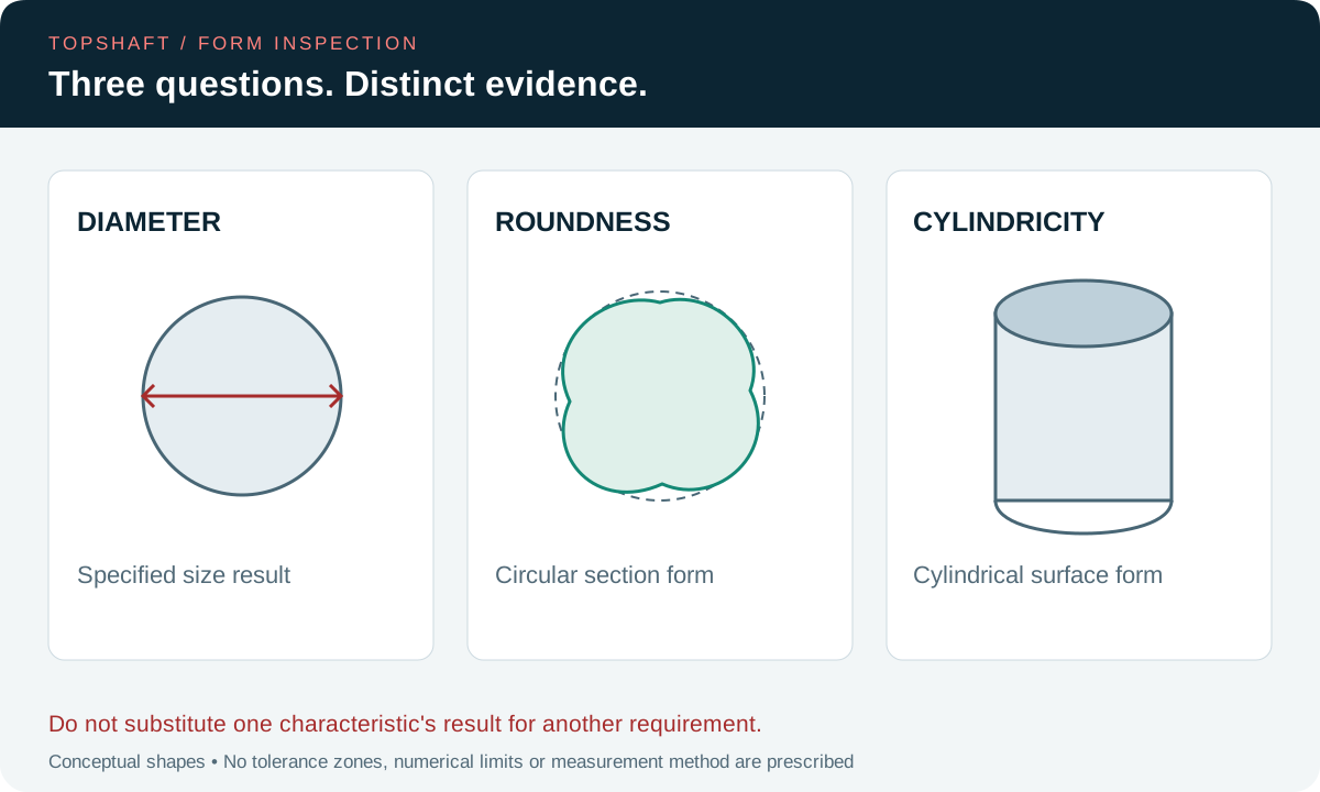
1. Separate size, section form and surface form
Diameter, roundness and cylindricity are different characteristics. A diameter requirement concerns size under its applicable definition. Roundness concerns circular form in a section; cylindricity concerns the cylindrical surface. Mitutoyo's explanation of geometric form verification distinguishes roundness and cylindricity and lists different evaluation references. It is a useful terminology source, not a substitute for the drawing or its governing standard.
Keep each specified requirement identifiable in the inspection plan. A few acceptable diameter readings do not, by themselves, document a complete roundness or cylindricity evaluation. Similarly, a reported form value does not replace the required size result. Determine which characteristics the design actually controls and obtain evidence for each. Avoid adding new acceptance requirements informally because a different parameter happens to be available in the measuring software.
2. Identify the exact journal and controlled extent
State which cylindrical feature is subject to the requirement and identify its axial extent. Distinguish neighboring bearing seats, seal journals and reliefs even when they share a nominal diameter. Clarify how the applicable definition treats interrupted areas, holes, grooves, chamfers and transitions. The inspector should not have to guess whether a trace crossing a groove represents the intended evaluation region.
Use a controlled drawing markup or characteristic identifier to connect the feature to its report entry. The inspection characteristic numbering guide explains this record connection. If an edge exclusion or limited evaluation length is necessary, establish it through the appropriate technical authority before inspection. A supplier-selected exclusion that removes an unfavorable result is not equivalent to an agreed interpretation of the requirement.
3. Keep runout evidence in its proper role
A runout check and a form evaluation should not be treated as interchangeable simply because both involve a rotating part. The datum relationship, setup, measured direction and evaluated characteristic matter. Read the actual callout rather than substituting a familiar indicator procedure. An indicator value without a stated setup can be difficult to interpret, particularly when the customer's question concerns a different geometric requirement.
Use the shaft runout guide for a separate review of that requirement and the datum selection guide to prepare setup questions. Keep the acceptance reference clear for each characteristic. Do not create an external datum requirement for a form control by habit, or assume that a setup used for runout automatically constitutes an appropriate evaluation of roundness or cylindricity.
4. Agree measurement coverage within each specimen
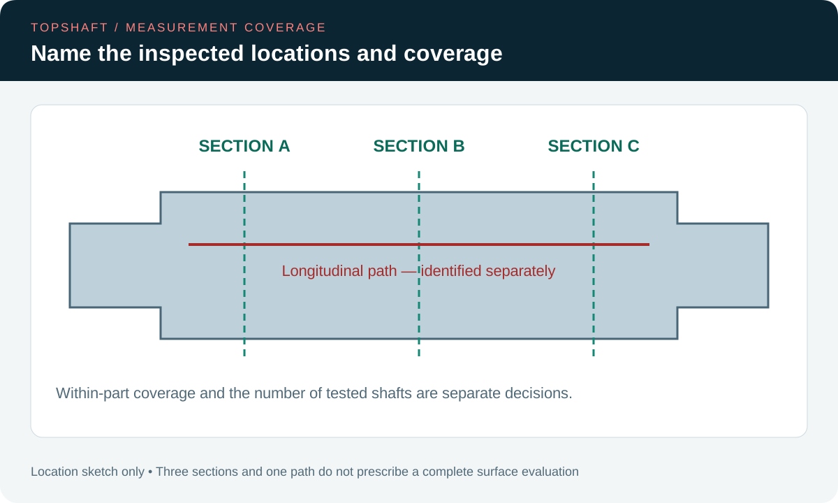
Describe how the proposed measurement represents the controlled feature. For section-based observations, identify the axial locations and relevant coverage around the circumference. For a cylindrical surface evaluation, establish the measurement strategy needed for that requirement and the applicable method. A report containing three section values should not silently be relabeled as a complete surface result without an agreed basis.
No universal number of points or traces is suitable for every feature, tolerance and method. The responsible metrology team should propose coverage appropriate to the required decision, and the customer should approve any contractual verification details. Record practical limitations such as inaccessible areas or interrupted surfaces. If the available setup cannot obtain the agreed evidence, resolve that limitation before accepting the reporting commitment or releasing the affected parts.
For example, a hypothetical receiving report might list roundness at the front, middle and rear of a journal. Those entries identify three evaluated sections, but the reader still needs their actual positions and the evaluation method. If the purchase order also calls for cylindricity, ask where that separate result and its supporting strategy are recorded. Do not combine the largest section value with an unrelated diameter spread to invent an overall acceptance number. The correct response to missing evidence is a documented request for the agreed evaluation, not a calculation assembled from convenient report fields. This example assigns neither a measurement spacing nor a tolerance; it shows why the report labels and supporting information must match the controlled characteristic.
5. Distinguish feature coverage from lot sampling
Two different sampling questions need answers. One concerns the observations taken on a single shaft. The other concerns which shafts are selected from the production lot. A detailed scan of one specimen does not establish that all pieces were inspected, and testing every piece with an insufficiently defined method does not resolve the feature coverage question. Keep both decisions visible.
Connect the specimen selection to the agreed inspection sampling plan. Record the lot identity, tested pieces and required reporting quantity. If the customer needs individual traceability for a critical journal, confirm that expectation rather than assuming a lot summary is enough. Conversely, do not present a sample report as a guarantee of measurements that were never performed on the remaining pieces.
6. Record the evaluation settings that affect meaning
Identify the evaluation method and settings needed to interpret the reported characteristic under the applicable requirement. Relevant information can include the reference or association method, filtering, evaluated length and treatment of excluded regions. The actual required settings must come from the agreed specification and verification method, not from a generic purchasing article. Different software labels should be reconciled before comparing results.
Retain the approved configuration or procedure reference with the result. A default setting may be convenient but is not automatically the required one. If a setting changes during an investigation, preserve the original result and identify the reason for the alternative evaluation. Do not choose whichever processing option produces the smallest number and then omit that choice from the report. The acceptance decision needs a controlled, reproducible basis.
7. Review the physical measurement conditions
Confirm that the fixture, support and contact arrangement are appropriate to the actual shaft and measurement objective. A long, slender or delicate component deserves a specific review of how it is held. Identify the specimen condition and any preparation required by the approved procedure. The aim is to measure the defined feature under agreed conditions, not to rely on an undocumented arrangement that another laboratory cannot reproduce.
Keep cleanliness and handling requirements proportionate to the measurement. Record relevant temperature conditions and stabilization requirements where specified. The inspection temperature guide provides related procurement questions. If contamination, seating or setup is suspected, document the investigation instead of quietly deleting an unfavorable reading. A repeated measurement should remain connected to the reason it was repeated and the conditions that changed.
| Inspection element | Information to agree | Reporting purpose |
|---|---|---|
| Characteristic | Size, roundness or cylindricity requirement | Prevent substitution of results |
| Feature extent | Journal identity and evaluation region | Locate the inspected surface |
| Coverage | Within-part strategy and lot selection | Explain what was observed |
| Evaluation | Method, settings and procedure reference | Make the result interpretable |
| Decision | Limit, uncertainty and acceptance rule | Support controlled release |
8. Link the result to an acceptance rule
Specify the tolerance and applicable decision rule before the measurements are reviewed. State the units clearly, especially when a report combines millimetres and micrometres. A chart's visual magnification is not the product tolerance, and a software display with additional digits is not evidence that the measurement has equivalent accuracy. Compare the reported quantity with the requirement it actually represents.
Consider measurement uncertainty in the way required by the agreed conformity evaluation. The measurement uncertainty guide explains why a nominal pass or fail label can be incomplete near a limit. Do not invent an acceptance margin after seeing a disputed result. If the customer and supplier use different methods or settings, reconcile the definition and evidence before treating the disagreement as proof that one organization measured incorrectly.
9. Ask for a report that can be reviewed
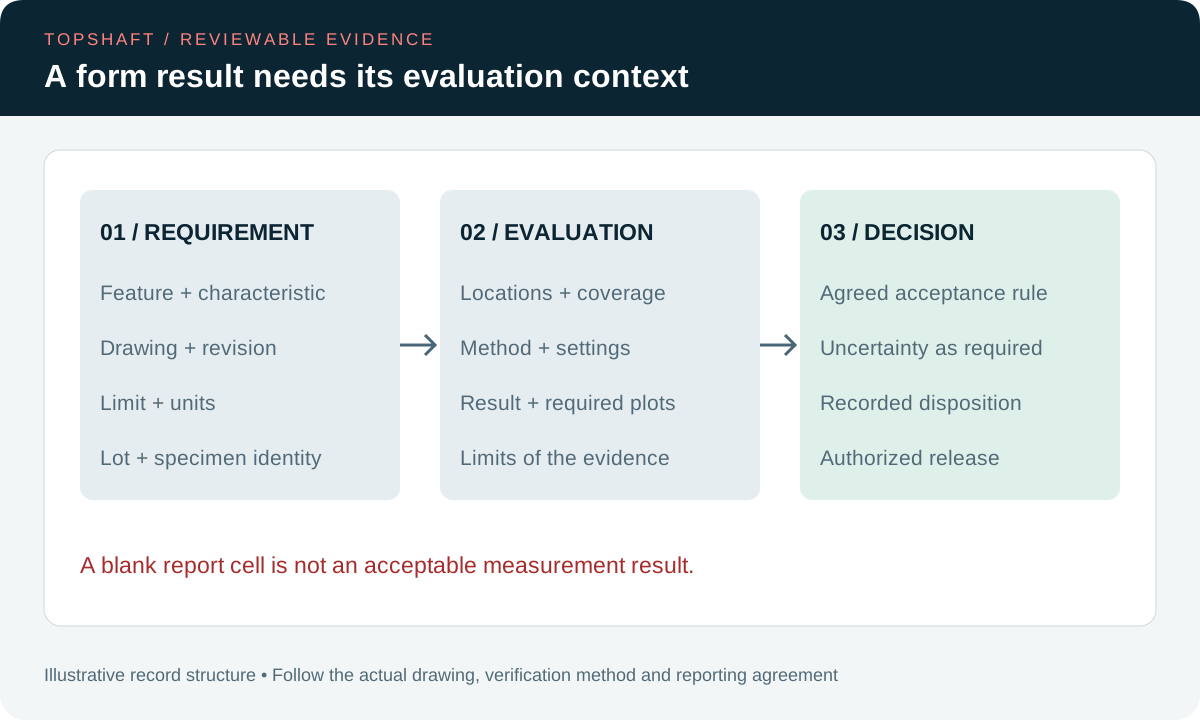
The report should identify the part, revision, lot and tested specimen, together with the feature and characteristic. Include the required method or procedure reference, evaluation coverage, settings and results. Where plots or underlying data are part of the agreed evidence, link them to the same record. A standalone polar plot with no feature identity or evaluation information is difficult to use for receiving acceptance.
Label maximum, individual section and overall surface results according to what they actually mean. If the planned evaluation could not be completed, state the limitation explicitly. A blank cell should not be interpreted as an acceptable result. Retain approved clarifications with the report so a later reviewer can determine what was inspected, what was excluded and which acceptance basis applied to the shipment.
10. Resolve disagreements before changing the shaft
When results differ, first compare specimen identity, feature location, measurement setup, coverage and evaluation settings. Preserve the original records and agree a controlled verification plan. This review may identify a definition or reporting problem; it may also confirm a product nonconformity. Do not assume that repeating measurements until one passes is a valid investigation or that a better-looking plot authorizes acceptance.
If physical correction is proposed, review its effects and obtain the necessary authorization. The rework and concession guide separates a proposed operation from an approved disposition and verified release. For a new RFQ, send the drawing, critical journal requirements and required inspection evidence through the contact page. Agree the actual scope and responsibilities before converting a general request for good roundness into a supply commitment.
Frequently asked questions
Does an acceptable diameter prove acceptable roundness?
Not by itself. A diameter result addresses the specified size measurement. A separate roundness requirement needs evidence appropriate to that characteristic and the governing definition. Keep the two report entries distinct when both are required rather than treating one set of readings as automatic proof of the other.
Can several roundness readings be called cylindricity?
Not without an appropriate, agreed surface evaluation. Section readings can contribute to a measurement strategy, but their presence alone does not establish the required cylindrical surface result. Confirm the method, coverage and evaluation basis before using a cylindricity label on the inspection report.
Must every shaft use the same measurement program?
No universal program follows from the word shaft. Feature length, access, tolerance, interrupted geometry and contractual method affect the inspection plan. Define an appropriate program with the responsible metrology team and retain the approved configuration so results are comparable across the intended production and receiving checks.
What should a buyer send with the RFQ?
Send the released drawing, identify the controlled journals and specify the required characteristics, reporting and lot sampling expectations. Include any invoked verification requirements or customer procedure. Ask the supplier to confirm feasibility and identify unresolved measurement questions before accepting a quotation that assumes a different inspection scope.