
Precision Shaft Inspection Temperature: Conditioning, Thermal Expansion And Acceptance — An OEM Checklist
A shaft can appear acceptable at the supplier and oversized at receiving inspection without either instrument being obviously defective. Before discussing rework, establish whether the measurements describe the same feature, material condition and reference temperature. Temperature is part of the measurement method, not merely a number displayed on the inspection-room wall. This guide helps purchasing, engineering and quality teams agree practical controls for precision shaft inspection without inventing a universal soaking time or temperature allowance.
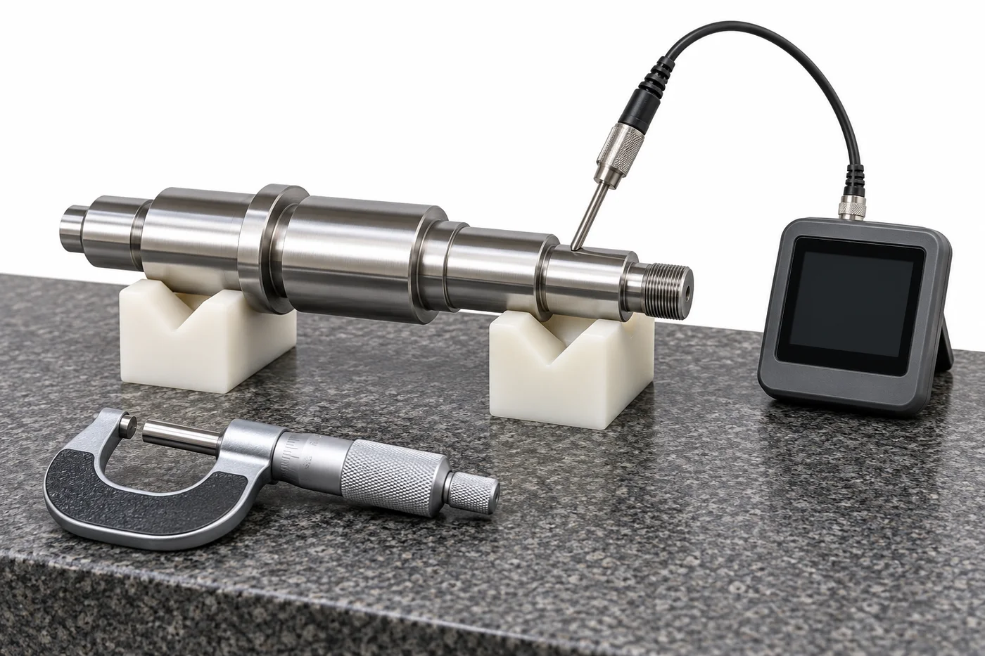
*Technical illustration, not a TOPSHAFT production photograph. Equipment arrangements are explanatory, not approved operating instructions.*
Define What The Dimension Refers To
Start with the drawing requirement. Which journal, shoulder distance or overall length is being evaluated? Does the reported result refer to the actual inspection temperature, or has it been corrected to an agreed reference temperature? A nominal diameter alone cannot answer those questions. Record the applicable drawing revision, units, material grade and finished condition before comparing inspection reports.
The NIST discussion of ISO 1 identifies 20 °C as the standard reference temperature for geometrical and dimensional properties. That reference does not mean every measurement must physically occur at exactly 20 °C. It does mean that departures, corrections and associated uncertainty require a technically justified method when relevant to the required accuracy. An air-conditioner setting alone does not establish the workpiece condition.
Keep dimensional conformity separate from operating behavior. A shaft specified at a reference temperature can expand in service, but a warm inspection reading is not automatically evidence that the drawing is wrong. Engineering must assess operational clearances separately. For the underlying fit definition, see the bearing journal specification guide, then add inspection conditions rather than quietly changing the dimensional limits.
Identify The Whole Thermal Measurement System
Consider the workpiece, measuring instrument, reference standard, support and surrounding air as a connected system. A shaft recently ground, washed or transported may not match the room temperature. A reference master stored in a different cabinet may also differ. Even if two objects eventually reach the same temperature, their expansion behavior need not match because their materials and construction can differ.
Ask where temperature is measured and why that location represents the dimension being inspected. A convenient room sensor cannot directly prove that a thick shaft core or bearing journal has stabilized. Likewise, a sensor on one end may not reveal a gradient along a long component. Select sensor locations, contact methods and handling precautions through the inspection plan; do not attach unapproved devices to a critical finished surface.
The NIST dimensional-metrology FAQ explains why temperature correction depends on both temperature and the coefficient of thermal expansion. Use that principle to question an unexplained corrected result. A displayed value with additional decimal places is not evidence that the temperature measurement, material assumption or instrument compensation is adequate for the acceptance decision.
Estimate Sensitivity Before Choosing Controls
An order-of-magnitude calculation helps determine whether temperature deserves closer control. For a simplified, uniformly heated dimension, the approximate change is delta L = alpha × L × delta T. Here alpha is an assumed linear expansion coefficient, L is the reference dimension and delta T is the temperature difference. This approximation is educational; a validated measurement procedure must address the real material and equipment.
For illustration only, assume alpha = 12 × 10^-6 per kelvin, a 50 mm diameter and a 5 K difference from the reference condition. The estimated diameter change is 0.003 mm, or 3 micrometres. With the same assumptions, a 500 mm length changes by about 0.030 mm. These numbers are not a specification for any steel grade, a tolerance recommendation or permission to subtract a fixed value from an inspection report.
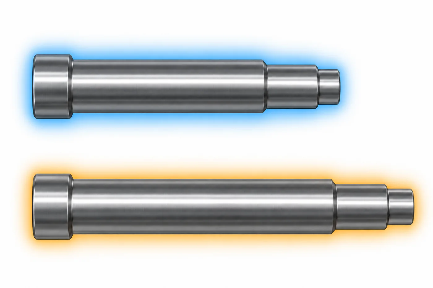
*Conceptual thermal-expansion illustration. The visual difference is exaggerated; no dimensional scale or material coefficient is implied.*
Compare estimated thermal sensitivity with the actual tolerance and the intended measurement uncertainty. A change that is irrelevant to one feature may matter to another. Do not choose inspection controls solely from the overall shaft length: a small bearing seat may have a demanding tolerance, while an overall length may be comparatively generous. Review critical characteristics individually and document the reasoning.
Condition Parts Without Inventing A Universal Waiting Time
Thermal conditioning means establishing suitable, sufficiently stable conditions for the planned measurement. It does not mean leaving every shaft on a bench for an arbitrary thirty minutes. Component size, material, initial temperature, packaging, air movement, supports and required uncertainty all affect the task. A universal waiting time can be either unnecessarily expensive or technically inadequate.
Agree a practical release criterion with the responsible metrology team. This may involve measured workpiece temperature, stability over a defined interval, comparison with relevant references and limits justified by the uncertainty assessment. The chosen criterion must be demonstrated for the part family and measurement method. Keep the record of actual conditions; a checked box saying “conditioned” is less useful than evidence showing what was observed.
Plan the queue so recently processed parts do not enter final inspection unnoticed. Separate incoming, conditioning and released-for-measurement locations. Identify the parts and their status, while protecting finished surfaces. A production bottleneck should trigger a scheduling or method review, not an undocumented decision to measure warm parts and assume the difference will disappear later.
Reduce Disturbance During The Measurement
Conditioning is not a permanent state. Moving a shaft next to a machine enclosure, placing it on a warmer support or holding a journal for an extended period can alter the conditions established earlier. Organize the inspection sequence to minimize unnecessary handling, while following the approved safety and surface-protection instructions. Do not assume gloves alone provide a quantified thermal barrier.
Check repeatability using a planned sequence rather than repeatedly touching the same feature until the reading stops moving. Identify whether change follows elapsed time, operator handling, measurement direction or instrument resetting. Those observations can help distinguish thermal drift from alignment, contact force, dirt or other causes. A trend is evidence to investigate, not proof of a particular cause by itself.
For long shafts or mixed-material setups, review whether the chosen support arrangement introduces additional effects during conditioning or measurement. The inspection team should evaluate both the physical setup and the mathematical correction. A change to supports, measurement sequence or master location may require the method to be reviewed even when the instrument model and nominal temperature setting remain unchanged.
Document Compensation Before Using It
Automatic temperature compensation can support a suitable measurement process, but it does not remove the need to know what is being compensated. Confirm the workpiece material setting, temperature input, reference temperature, instrument configuration and relevant software version. Follow the equipment manufacturer's instructions and the approved procedure. Do not assume a system compensates the workpiece simply because it compensates its own measuring scale.
Record whether the report contains raw, corrected or both types of results. Preserve enough information to reconstruct the correction, including the coefficient source and any approved limitations. If the material grade or supplied condition changes, review whether the previous assumptions remain appropriate. A coefficient copied from an unrelated alloy can make a numerically tidy report less reliable rather than more reliable.
Include temperature measurement in the equipment review. Sensor resolution, calibration information, placement, contact quality and response can all affect the usefulness of its reading. A sensor that measures air reliably is not automatically suitable for a contact measurement on a narrow journal. Establish the intended application and assess whether the measurement chain can support the uncertainty claimed for the dimensional result.
Never correct a thermal gradient by pretending the entire shaft has one known uniform temperature. Similarly, a simple diameter correction cannot establish roundness, straightness or runout conformity. Those characteristics also depend on the complete measurement setup and method. Use the shaft runout guide to define the geometric evaluation separately from the temperature strategy.
Build A Useful Inspection Agreement
Use the following checklist to assign responsibilities before an order is released. Fill it with project-specific requirements; it is not a generic acceptance standard. Keep the supplier's final inspection and the customer's receiving inspection consistent enough that disagreement can be investigated using comparable evidence.
| Topic | Agree before production | Evidence to retain |
|---|---|---|
| Reference condition | Applicable drawing, units and reference temperature | Approved drawing and inspection plan |
| Material basis | Grade, condition and coefficient source if used | Material identity and calculation assumptions |
| Conditioning | Validated release criterion and handling method | Observed temperatures, times and status |
| Equipment | Instrument, master, sensor and compensation scope | Identifiers, settings and relevant calibration status |
| Result | Feature location, method, raw or corrected value | Inspection record and uncertainty where required |
| Acceptance | Agreed decision rule and escalation route | Authorized disposition and supporting evidence |
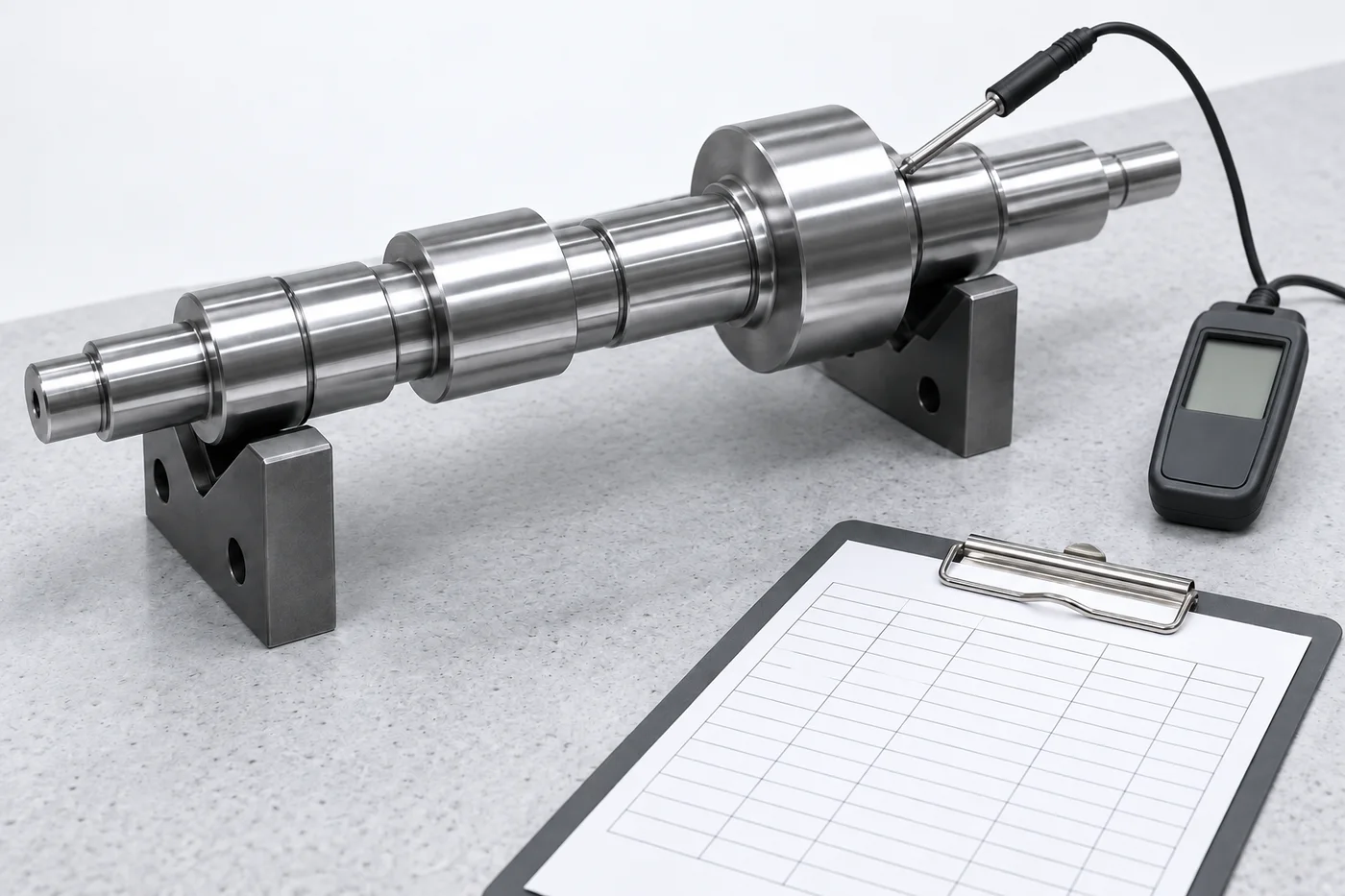
*Illustrative record arrangement. Blank displays and forms do not represent measured values, calibration certificates or customer results.*
Resolve Borderline Results Before Ordering Rework
When a value sits near a limit, do not average incompatible reports until the answer appears acceptable. Confirm part identity, measurement location, surface condition, instrument setup and temperature basis first. Re-measure under an agreed, stable condition using an appropriate method. Preserve the original records alongside the repeat results so the investigation remains traceable.
The acceptance decision should follow the agreed decision rule and relevant uncertainty treatment, not the operator's preference. If the order does not define how to handle borderline results, escalate to the responsible quality and engineering functions before shipment or rework. Temperature cannot be used as an automatic excuse to accept a genuinely nonconforming feature.
Avoid irreversible machining while the measurement basis remains disputed. Removing a few micrometres from a journal can affect fit, surface finish, coating allowance or subsequent processing. Use the drawing revision and change-control guide when an authorized change is necessary. Record the disposition instead of allowing an informal inspection disagreement to become an unrecorded design change.
Connect The RFQ To Receiving Inspection
At quotation stage, identify the characteristics whose acceptance is especially sensitive to measurement conditions. Ask the supplier to explain the proposed inspection route and any external measurement services included in scope. Do not infer a controlled laboratory, particular sensor capability or accredited service from a general statement about precision manufacturing. Confirm the required evidence and commercial responsibility explicitly.
Receiving inspection should have access to the approved conditions, not only a pass certificate. Protect traceability between the shaft, supplier report and customer check. If shipping moves parts between very different environments, allow the receiving process to establish its own suitable measurement condition. The first-article inspection guide helps organize that initial comparison before routine deliveries begin.
For recurring orders, review the process after a meaningful change, such as a new material, instrument, facility arrangement or inspection subcontractor. Keep approved assumptions available to both organizations. If an alternate method is proposed to reduce lead time, assess it against the original requirements before use. Commercial urgency should not silently change the reference condition, the decision rule or the evidence required for shipment approval.
Questions OEM Buyers Commonly Ask
Must Every Shaft Be Measured In A 20 °C Room?
Not necessarily. The reference condition and required accuracy determine what controls or justified corrections are needed. A room label does not prove the workpiece, instrument and reference are at a suitable condition. Use a validated method and retain relevant evidence.
How Long Should A Shaft Stabilize Before Inspection?
There is no universal duration. Define and demonstrate a release criterion for the component family, starting condition and measurement method. Size, material, packaging and required uncertainty can change the time needed. Do not replace validation with an arbitrary waiting period.
Can We Use The Same Expansion Coefficient For All Shafts?
No. Confirm the actual material basis and the applicability of the selected coefficient. The illustrative value in this article is not a recommended database entry. Where uncertainty in the coefficient matters, include it in the assessment rather than treating it as exact.
Does A Calibration Certificate Eliminate Temperature Effects?
No. Calibration information is important, but actual use conditions still matter. Check the instrument, reference and temperature inputs as a measurement system. Determine whether compensation covers the instrument, the workpiece or both, and follow the approved equipment instructions.
Should The Supplier Report Raw Or Corrected Dimensions?
Agree this before production. When correction is used, identify the reference condition and retain the assumptions and inputs needed for review. Reporting both can help an investigation, but the acceptance basis must remain unambiguous and consistent with the agreed inspection plan.
What Should We Send With A Temperature-Sensitive RFQ?
Provide the drawing revision, critical features, material and finished condition, tolerance requirements, expected evidence and any required decision rule. Ask for clarification of proposed conditioning and measurement methods. The precision shaft RFQ checklist is a useful starting point for assembling the complete technical package.
Make Temperature A Shared Requirement
The aim is not to make every inspection unnecessarily elaborate. It is to use controls proportionate to the feature, tolerance and decision. Agree the reference condition, validate the measurement method and retain sufficient records to explain the result. A clear temperature strategy helps supplier and customer discuss the same shaft dimension, while keeping design changes, operational behavior and measurement uncertainty in their proper places.