
How To Specify A Shaft Seal Journal: Surface Texture, Lead And Inspection
A shaft seal journal needs more than a diameter and a roughness value. You must define the contact zone, surface condition, geometry and installation route. This guide helps you turn those requirements into a drawing and inspection plan before ordering custom shafts.
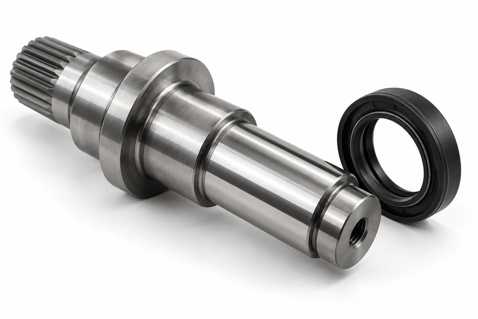
*Illustrative product rendering, not a TOPSHAFT factory photograph.*
Start With The Seal And Its Operating Conditions
Your shaft specification should follow the selected seal and the actual operating conditions.
Identify the seal manufacturer, part number and current application guidance. Record the lubricant or process fluid, temperature, speed and rotation direction. Include contamination exposure, pressure conditions and expected shaft movement. Ask the seal supplier to review unusual operating combinations.
Do not transfer requirements between elastomeric and PTFE seals without checking their guidance. Different designs can require different surfaces and assembly practices. A drawing copied from another machine may describe the wrong interface.
Create a short application sheet alongside your shaft drawing. Give your machining supplier the information that affects manufacturing and acceptance. Keep seal selection responsibility clear between your engineering team, seal supplier and shaft manufacturer.
SKF’s seal analysis guidance explains why lubrication, temperature, contamination and alignment belong in the sealing review. Do not treat a shaft specification as a substitute for that review.
Locate The Seal Contact Zone On Your Drawing
The drawing should identify the complete cylindrical region where the sealing lip may operate.
Locate this region from a functional shoulder or another agreed reference. Include axial assembly variation and permissible movement. Show where the finished sealing surface begins and ends. Keep its boundaries separate from adjacent bearing seats.
A general roughness symbol for the entire shaft can leave the actual contact region ambiguous. Use a local callout or clearly identified surface designation. Connect every special requirement to that same designation.
Check that grooves, cross-holes, keyways and transition radii remain outside the intended contact region. Review the tolerance stack instead of assuming the nominal assembly position is sufficient. An apparently clear journal can become unsuitable when assembly variation moves the lip.
Treat replacement positions as a separate design question. If maintenance may place a new seal at another axial location, define the permitted replacement region. Do not assume every neighboring surface has the same finish.
Specify Surface Texture Beyond Ra
Surface texture acceptance should describe the selected seal’s requirements, not merely a preferred visual appearance.
Ra summarizes one aspect of a measured profile. It does not uniquely describe peaks, valleys or directional texture. Two surfaces can share an Ra result while having different profiles.
Parker’s Rotary Seal Design Guide specifically discusses this limitation for rotary sealing surfaces. Follow the requirements applicable to your selected seal, rather than combining unrelated catalogue values.
Specify any additional texture parameters the application requires. Identify the measurement standard and edition, evaluation settings and trace direction. Make the supplier’s measurement setup consistent with your receiving inspection.
Write units explicitly. Micrometres and microinches are not interchangeable. Check legacy drawings carefully when roughness notes have been copied between systems.
Avoid asking for an undefined “mirror finish.” That phrase provides no reproducible acceptance criterion. Likewise, do not assume a lower Ra automatically improves the seal system.
For broader drawing guidance, see shaft surface finish specifications. Keep the seal journal’s local requirements distinct from cosmetic surfaces.
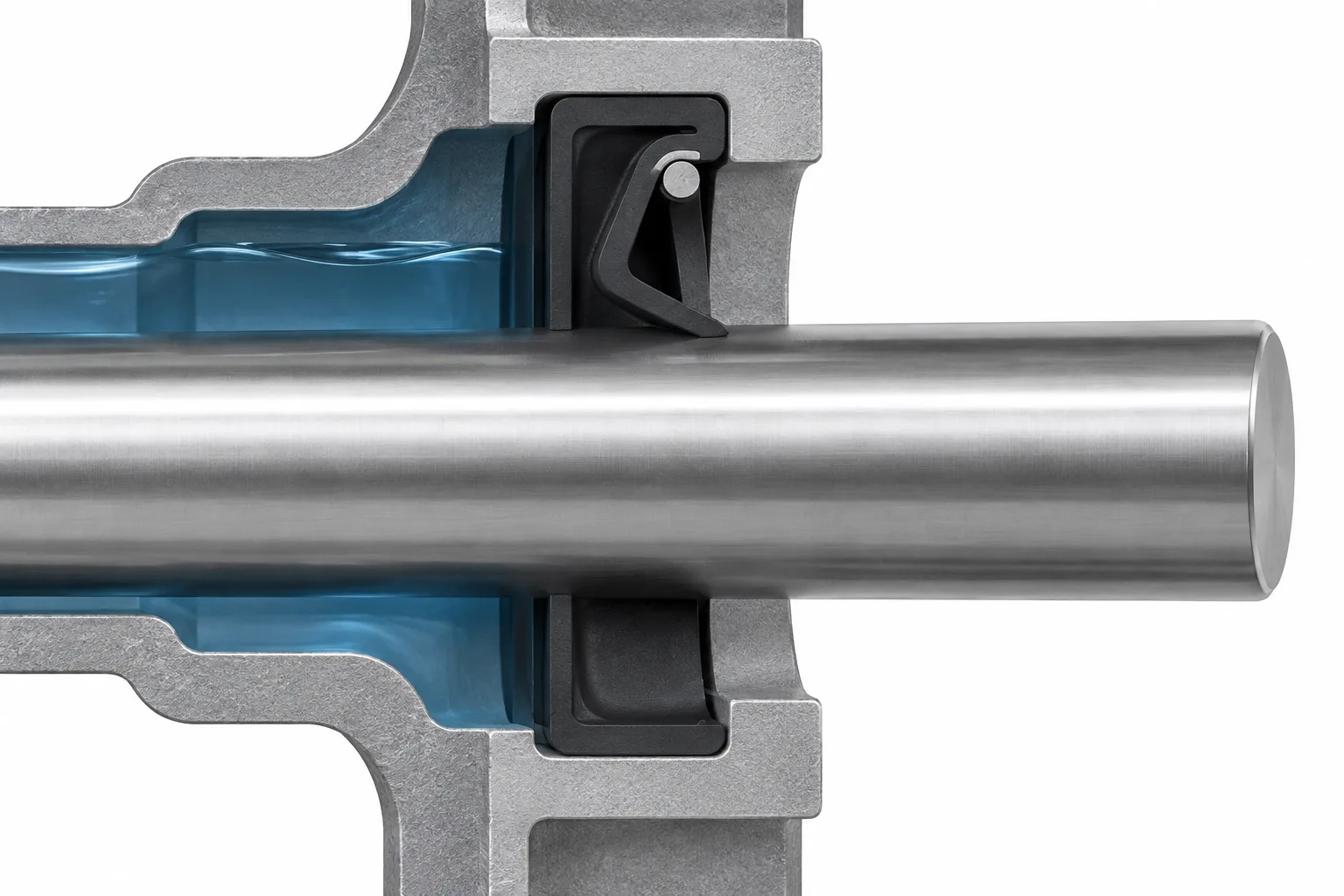
*Conceptual sealing interface, not a production assembly drawing.*
Separate Machining Lead From Installation Lead-In
Machining lead concerns directional surface texture; an installation lead-in concerns the geometry used during assembly.
A shallow helical surface pattern can influence fluid transport during rotation. Its effect depends on the texture, rotation and sealing system. An ordinary roughness result alone does not establish acceptable shaft lead.
Specify the seal supplier’s applicable lead requirement and an agreed verification method. A process description can support control, but it should not replace required acceptance evidence.
An installation chamfer has a different purpose. It provides a transition as the seal passes onto the shaft. Define its geometry from the selected seal’s installation guidance.
Avoid a drawing note that says only “lead required.” That wording can mean two different things. Use separate notes for surface lead control and entry geometry.
Review reverse operation as well as normal rotation. If a machine changes direction, tell the seal supplier and shaft manufacturer. Do not approve a directional assumption that excludes a real operating mode.
Coordinate Material, Hardness And Final Finishing
Material and treatment requirements should support the finished sealing interface and the complete shaft design.
Record the material grade, delivery condition and required treatment. Distinguish surface hardness from core requirements when the design needs both. Confirm where hardness will be measured and which method applies.
Do not copy a universal hardness minimum into every shaft order. Required values depend on the seal system, wear environment and selected counterface. Use the current guidance for your application.
If a coating is proposed, review its compatibility with the seal supplier. Clarify the final dimensions and texture after all processing. Specify any finishing permitted after coating and how the coating will be inspected.
Define the sequence before production starts. Heat treatment, coating and final finishing must leave the journal meeting the final drawing. A compliant intermediate surface is not sufficient.
Use the shaft heat-treatment specification guide to organize related hardness and processing notes. Keep every requirement tied to the appropriate region.
Reference Geometry To The Functional Assembly
Geometry requirements should relate the seal journal to the shaft’s actual support and the housing interface.
Select datums that represent the intended assembly. Avoid choosing a convenient inspection surface without checking its functional meaning. Record how the shaft will be supported during measurement.
Distinguish journal form, rotational runout and shaft-to-housing alignment. These describe different conditions. A shaft inspection report cannot prove housing alignment by itself.
Use appropriate geometric controls where the design requires them. Do not treat diameter tolerance as a complete description of rotation. Ask engineering to define acceptance limits from the assembly’s needs.
Document the indicator location and setup when runout forms part of acceptance. Make the inspection repeatable between supplier and customer. Include the drawing revision on the report.
The shaft runout guide explains how datum choices affect inspection. Apply that logic to the seal’s working location, not only the shaft ends.
Agree On The Manufacturing Route And Change Control
The approved route should produce the specified finished surface and preserve it through subsequent operations.
Discuss turning, heat treatment, grinding and any additional finishing as one connected plan. Do not accept a generic “CNC machined” description as proof of seal-journal conformity. Separate dimensional capability from texture verification.
Ask which operations establish the functional references. Identify when the final journal receives its last machining operation. Review any later clamping, handling or deburring that could affect it.
If a different finishing route is proposed, request evidence against the same acceptance criteria. Do not approve a substitution solely because the part looks smoother.
Define which changes require customer review. Examples include a new coating, revised finishing process or changed inspection method. Keep the level of control proportionate to application risk.
Prototype approval should identify exactly what was inspected. Record unresolved validation items separately. A successful short bench trial should not silently replace specified endurance or operating tests.
Plan Installation Before Approving The Shaft
Installation planning should prevent the sealing lip from crossing damaging features without suitable protection.
Trace the complete assembly path. Check threads, splines, grooves, edges and shoulders that the seal must pass. Determine where an installation sleeve or another approved protection method is necessary.
SKF’s industrial shaft-seal catalogue covers counterface and installation considerations. Use the instructions applicable to your seal rather than inventing a standard chamfer for every design.
Review both the new-build sequence and service replacement procedure. A shaft can be straightforward to assemble before other components are installed. The maintenance route may be more restrictive.
Keep cleaning, lubrication and installation instructions aligned with the seal supplier. Do not assume an assembly lubricant is compatible because it is available nearby.
Inspect accessible features before assembly hides them. Record any handling damage found at that stage. This helps distinguish manufacturing nonconformity from damage introduced during installation.
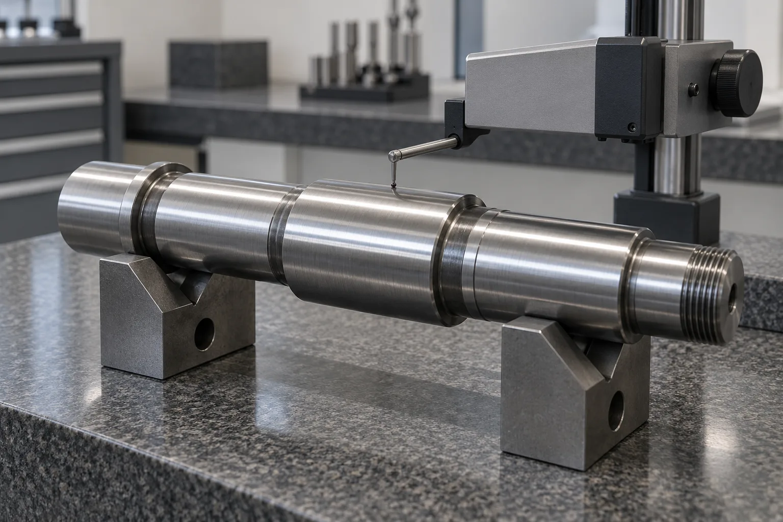
*Illustrative inspection arrangement, not evidence of company equipment.*
Define An Inspection Plan That Can Be Repeated
An inspection plan should connect each drawing requirement to a method, location and recorded result.
Agree on these details before accepting the quotation. Do not leave specialized lead verification until the first shipment. Ask the supplier to disclose unavailable methods and proposed alternatives.
| Requirement | Information To Agree Before Ordering |
|---|---|
| Journal diameter | Measuring locations, instrument and final processing condition |
| Surface texture | Parameters, units, trace direction and evaluation settings |
| Machining lead | Acceptance criterion, method and reporting format |
| Geometry | Datums, support arrangement and measurement location |
| Hardness | Test method, test region and applicable treatment condition |
| Surface condition | Visual criteria, lighting and permitted defect limits |
Choose first-article and repeat-production checks according to risk. Some requirements may need different frequencies. Specify the sampling plan instead of relying on “standard inspection.”
Request traceable records where your purchase order requires them. Include part number, revision, lot identification and inspection date. Define how nonconforming parts will be segregated and reported.
Do not assume every instrument can measure every journal. Small diameters, short contact zones and nearby shoulders may restrict access. Review the actual geometry with the inspection team.
Compare Quotations On The Same Technical Basis
Useful price comparisons require the same finished-part specification and inspection scope.
Separate material, treatment, finishing, inspection and documentation costs. Ask whether specialized testing is included or quoted separately. Review setup costs and repeat-order assumptions.
An inexpensive quote may omit a requirement rather than use a more efficient process. Conversely, unnecessary blanket finishing requirements can increase cost without improving the functional interface.
Identify which regions truly require special processing. Keep nonfunctional surfaces proportionate to their role. Obtain engineering approval before relaxing a specified requirement.
Discuss quantities, annual demand and expected drawing changes. These affect production planning and the economics of inspection. Avoid demanding a fixed unit price before the technical scope is settled.
Use the precision-shaft RFQ checklist to make competing quotations easier to compare.
Protect The Accepted Surface Through Delivery
Packaging and receiving checks should preserve the journal condition accepted during final inspection.
Specify protection that does not scratch the working surface. Review contact points, shaft movement inside the package and compatibility of protective materials. Do not allow loose accessories to rub against the journal.
Provide any agreed cleaning or preservation instructions. Make it clear whether protection must be removed before assembly. Avoid undocumented chemicals on a sealing interface.
At receiving, check packaging condition before unpacking. Record visible impact or abrasion and retain lot identification. Isolate suspect parts instead of assembling them and investigating later.
The precision-shaft packaging guide covers protection planning in more detail.
Frequently Asked Questions
Clear answers help you avoid ambiguous drawing notes and purchasing assumptions.
Is Ra Enough To Accept A Seal Journal?
Not by itself when the selected seal requires additional texture or lead controls. Follow its complete counterface specification.
Can I Use A Bearing-Journal Finish For The Seal Area?
Only after checking the seal requirements. Shared diameter or nearby location does not establish the same functional acceptance criteria.
Does Grinding Automatically Prove Acceptable Machining Lead?
No. A process name does not establish every finished-surface requirement. Agree on appropriate process control and verification.
Should Every Seal Journal Have The Same Hardness?
No. Confirm the requirement for your seal, material, treatment and operating conditions before releasing the drawing.
Can A Coating Replace The Original Journal Specification?
Not automatically. Review the coated interface and define final dimensional, texture and compatibility requirements before approving the change.
Who Sets The Acceptance Limits?
Your responsible engineering team should approve them using the selected seal’s guidance and application requirements.
Can A Shaft Report Prove The Complete Assembly Will Not Leak?
No. Shaft conformity is one part of sealing performance. Assembly, housing, lubrication and operating validation remain separate responsibilities.
What Should I Send With An RFQ?
Send the drawing revision, seal identification, operating conditions, quantities and required inspection evidence. Include relevant assembly details.
Request A Drawing-Based Review
A useful review begins with your drawing and the selected seal’s requirements.
TOPSHAFT’s published Inspection And Quality page describes drawing-based inspection review. Specialized seal-journal checks must still be confirmed for your project.
Contact TOPSHAFT with your drawing, seal information, quantities and acceptance requirements. Ask for a manufacturing and inspection review before releasing the order.