
How To Specify A Shaft Keyway: Dimensions, Tolerances And Inspection
A shaft keyway is a torque-transmitting feature, not just a milled slot. Its width, depth, length, position, edge condition and relationship to the mating hub all affect assembly, key fit and load transfer. A clear drawing prevents a supplier from having to guess which standard, reference system or inspection method applies.
Start With The Mating Hub And Key Standard
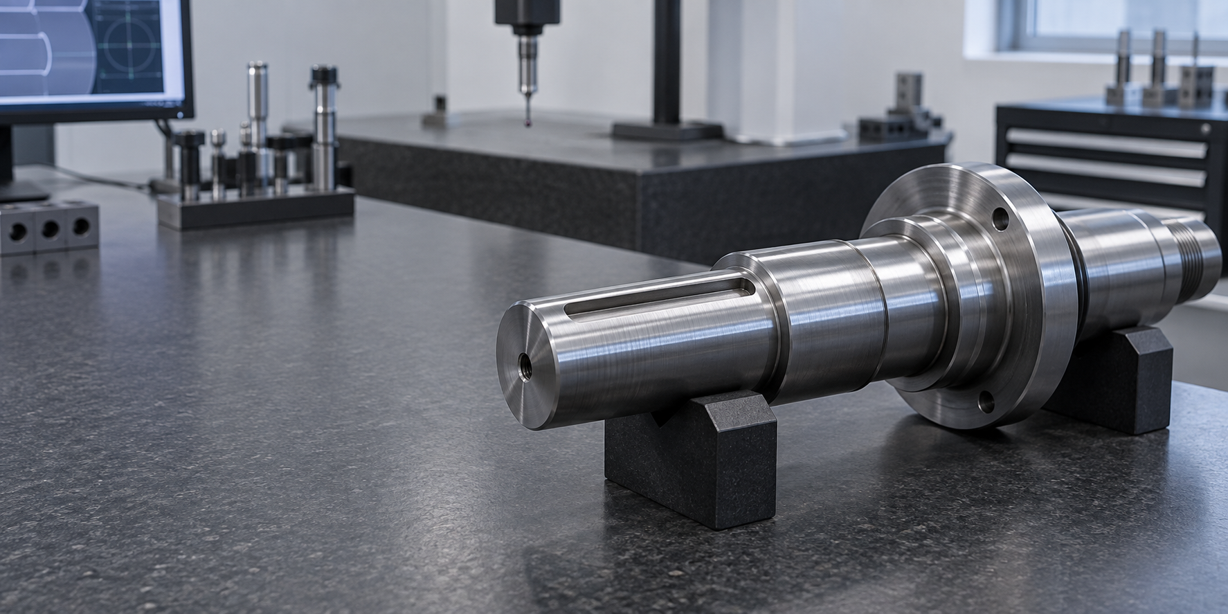
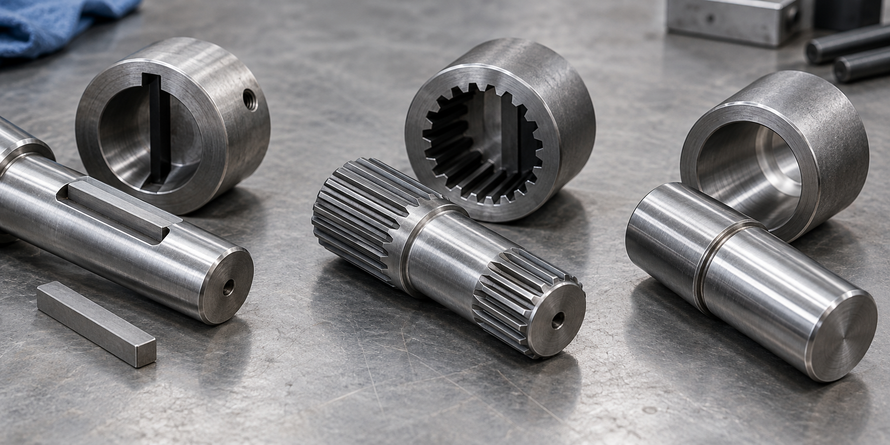
The shaft keyway should be defined together with the key and hub keyway. First identify the key type, nominal shaft diameter, hub geometry, torque direction, service load and applicable standard. ISO, DIN, ANSI and customer-specific systems can use different dimensions and tolerance conventions; a standard name without the relevant size or drawing revision may still be ambiguous.
State whether the key is intended to be a sliding assembly, a closer fit, or part of a controlled interference condition. The complete assembly—not the shaft feature alone—determines what needs to be controlled.
Define Width, Depth And Length Clearly
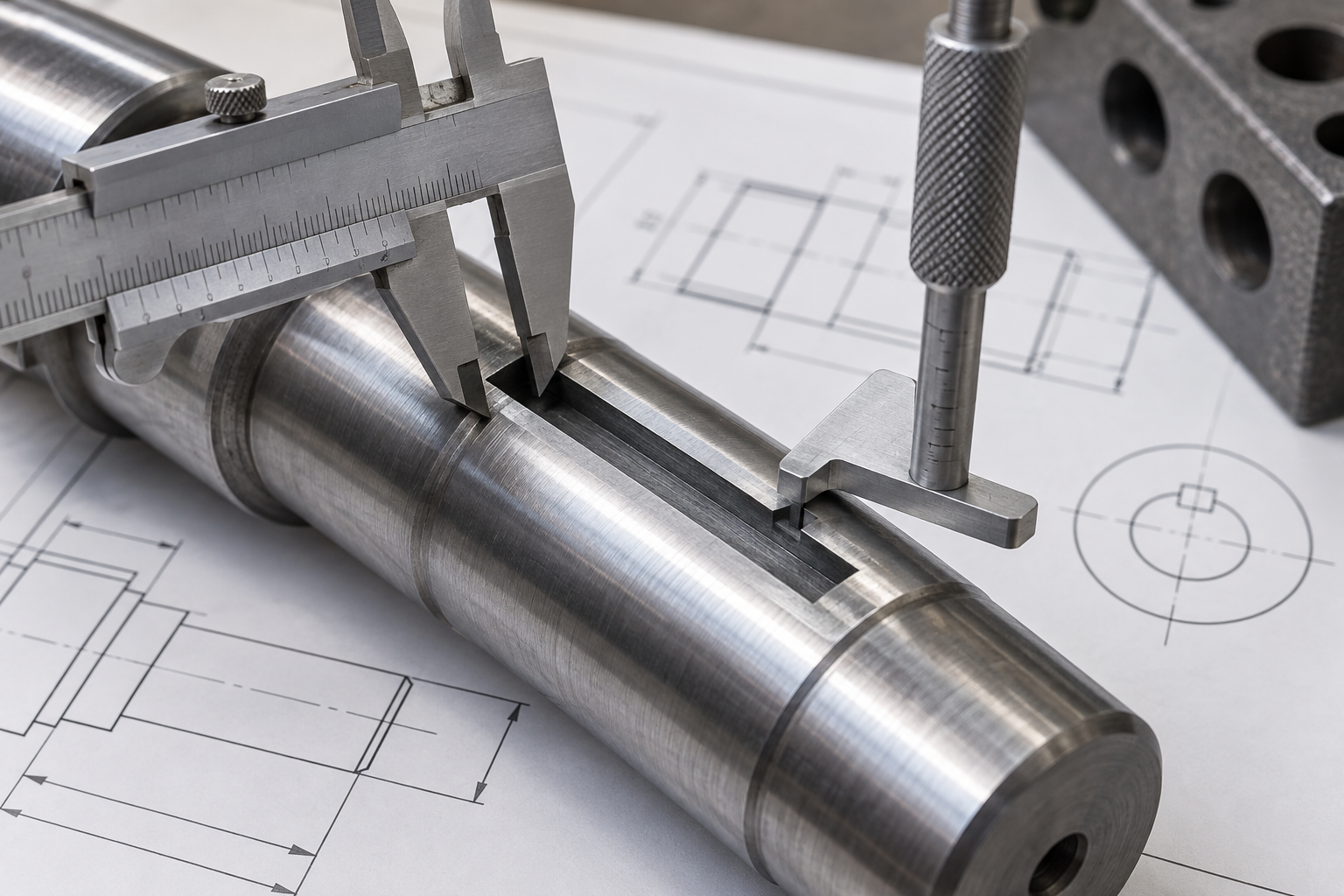
At minimum, a usable callout identifies the nominal keyway width, radial depth, axial length and the dimension references. Do not rely on a visual slot shape when the feature has a functional location.
The drawing should also clarify whether the keyway has a flat end, a radiused cutter end, runout clearance, or a specified transition into a shoulder. If the length begins from a shoulder, end face or datum plane, show that relationship directly. This protects the hub location and prevents an otherwise correct keyway from being machined in the wrong axial position.
Set Tolerances Around The Functional Requirement
Keyway width is usually the feature most directly related to key fit, but it is not the only control. Depth affects how the key shares contact with the shaft and hub. Position affects the assembled hub location. Surface condition and burrs can affect both installation and seating.
Use the applicable standard or your controlled assembly requirement to choose tolerances. Avoid applying a tighter value simply because it appears more precise. Unnecessary tolerances can increase machining and inspection cost without improving torque transfer or assembly performance.
If rotational orientation matters—for example when a keyway aligns a rotor, cam, timing feature or sensor target—define the angular relationship to a datum feature. A nominally correct slot can still be functionally wrong if it is clocked from an uncontrolled reference.
Choose A Manufacturing Method That Fits The Geometry
Milling, broaching, slotting, shaping or other processes may be used depending on the shaft size, material, production quantity, access and specified geometry. The drawing should define the result, not force a process unless the process itself is required by the application.
For hardened or heat-treated shafts, consider whether the keyway must be machined before treatment, after treatment, or followed by a finishing operation. The sequence can affect distortion, burr removal, edge condition and final dimensions.
Call Out Edge Condition And Deburring
Sharp edges around a keyway can damage a key, create assembly interference, or release loose material into a rotating system. A general “remove burrs” note may not be enough when a functional edge needs a controlled break or when a sharp corner is required by the mating component.
Identify the edge condition at the slot opening and ends. If the keyway must be free of raised material after coating, heat treatment or grinding, state that condition and agree how it will be checked.
Plan Inspection Before The First Article
Inspection should follow the same references used on the drawing. Width can be measured with calibrated gauges, calipers or a suitable metrology method; depth and axial position need their own approach. Where orientation matters, inspection must relate the keyway to the defined datum axis, face or feature.
For a first article, agree which results need to be recorded: keyway width, depth, length, axial position, angular orientation, edge condition and any related shaft diameter or runout requirement. This keeps the inspection record useful for the actual assembly rather than only the individual slot.
Shaft Keyway Drawing Checklist
- Applicable key and keyway standard, including the relevant size.
- Keyway width, depth and axial length with units and tolerances.
- The datum, shoulder or end face that establishes axial position.
- Flat-end, radiused-end and transition geometry where required.
- Angular orientation relative to a functional datum when clocking matters.
- Material, heat treatment, coating and required process sequence.
- Edge-break, deburring and surface-condition requirements.
- First-article inspection points and the required acceptance evidence.
FAQ
Should A Shaft Keyway Follow A Standard?
Usually, yes. Referencing the correct standard and size gives the supplier a common starting point. The drawing should still define any project-specific tolerance, position or edge-condition requirement.
Is Keyway Width The Only Important Dimension?
No. Depth, axial location, end geometry, orientation and burr condition can all affect the fit and function of the assembled shaft and hub.
Can A Keyway Be Added After Heat Treatment?
It may be possible, but the route depends on hardness, geometry and final requirements. Identify the required final condition so the manufacturing sequence can be reviewed before production.
Ready To Review Your Keyway Drawing?
Send your drawing and requirements with the shaft diameter, mating hub or key information, material, quantity and any critical assembly conditions. TOPSHAFT can review the information needed for a practical manufacturing discussion.