
Shaft Shoulders, Fillet Radii and Relief Grooves: An OEM Drawing Checklist
A shaft can pass its diameter inspection and still create an assembly problem. A bearing may stop against a corner instead of seating against the intended shoulder. A spacer may bridge a radius. A finishing operation may leave the transition different from the drawing requirement.
These problems are not solved by tightening every tolerance. You need to define the relationship between the shaft, its mating components and the manufacturing route.
This checklist helps purchasing, engineering and quality teams review those relationships before ordering. It does not provide universal shoulder dimensions or replace bearing-manufacturer guidance and application-specific engineering calculations.
1. Identify What the Shoulder Must Do
A shoulder is a change in shaft diameter, but its function depends on the assembly. It may locate a bearing ring, support a spacer or establish the axial position of a rotating component.
Start by identifying the actual contact surface. Which component touches the shoulder? Which direction can it load that surface? Is the shoulder part of an axial stack that determines clearance or preload?
Separate axial location from radial fit. The bearing-seat diameter controls one relationship. The shoulder location and supporting face control others. An acceptable diameter does not demonstrate correct axial positioning.
Also distinguish an intentional locating shoulder from a diameter transition that has no locating function. Giving both the same inspection requirements can add cost without improving assembly performance.
Use a marked assembly view to identify functional surfaces. A supplier should not have to infer them from the appearance of a stepped shaft.
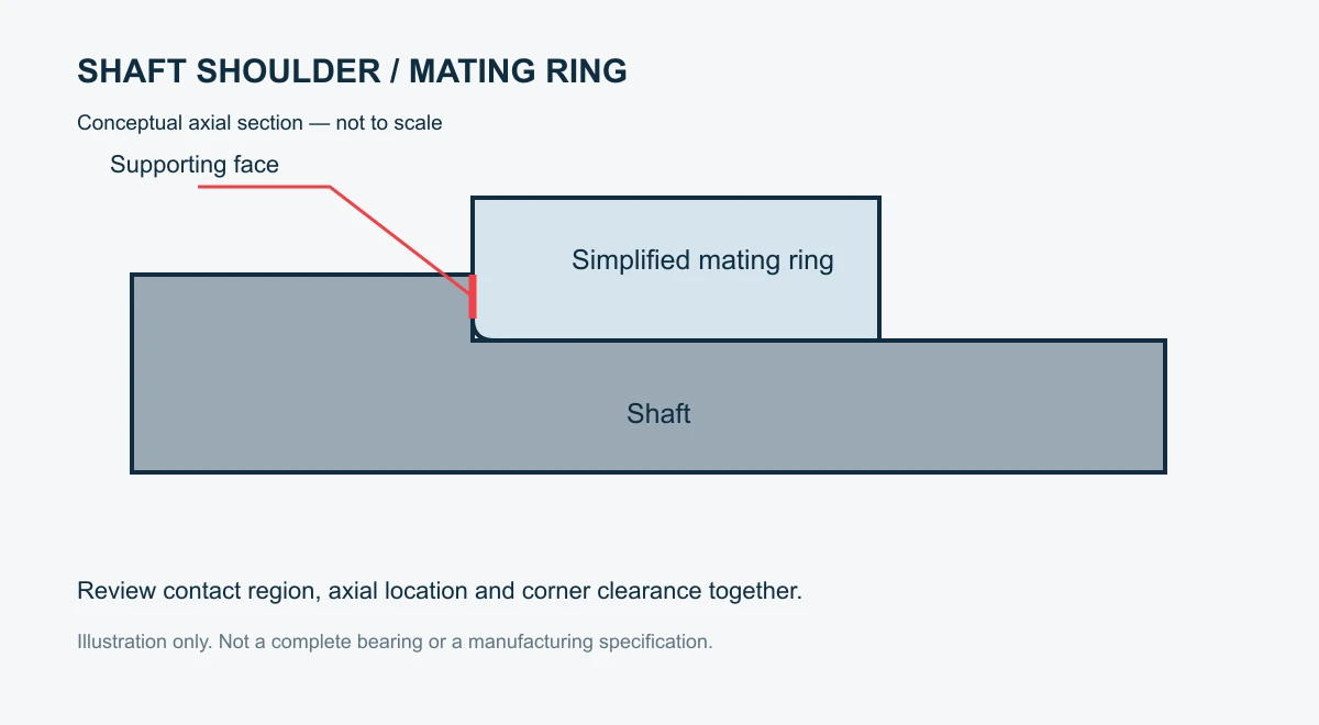
Schematic illustration only. The simplified ring is not a complete bearing, and the geometry is not dimensioned for manufacture.
2. Review the Actual Mating Component
The shaft drawing is only part of the interface. Obtain the selected bearing or spacer drawing and confirm its revision or product designation.
For a bearing, review the manufacturer's recommended abutment dimensions and permissible corner geometry for that specific product. Do not transfer a radius value from a visually similar bearing.
SKF product data distinguishes bearing chamfer dimensions, shaft abutment dimensions and permitted shaft fillet radii. These are related requirements, not interchangeable labels. For example, its 51216 product page lists them separately. That product's values are not general shaft-design recommendations.
Confirm whether the assembly uses a spacer, seal carrier or another intermediate component. Its edge relief may determine clearance even when the bearing itself would fit.
Record substitutions explicitly. A replacement component can change the allowable corner or supporting geometry while retaining the same nominal bore diameter.
3. Balance Fillet Clearance and Structural Requirements
A fillet smooths the transition between diameters. Its suitability must be assessed with the surrounding geometry, material, loading and mating components.
Making a fillet smaller may improve local clearance, but that does not make it the better structural choice. Making it larger may improve a transition while obstructing the component that must seat beside it.
Your engineer should resolve that trade-off before releasing the drawing. The supplier should not independently choose between assembly clearance and a load-related design requirement.
Specify the permitted radius or profile clearly. If a maximum radius matters for clearance, make that requirement visible. If a minimum radius or a controlled blend matters structurally, state that as well.
Do not assume a general edge-break note defines a functional fillet. Review conflicting notes before quotation. Where strength or fatigue performance matters, the transition requires application-specific assessment rather than a generic machining rule.
4. Define the Effective Supporting Face
The shoulder's outside diameter does not fully describe the surface available for support. A fillet, groove or chamfer can reduce the usable contact area.
Identify the intended annular supporting region. Check that it supports the relevant ring or spacer without unwanted contact with adjacent moving or stationary parts.
Review the complete assembly, including seals and cages where relevant. A shoulder that appears suitable in an isolated shaft view may conflict with another component.
Consider whether the shoulder is continuous or interrupted by another feature. A keyway, cross-hole or local relief near the supporting region deserves specific review.
If contact width is important, communicate the functional requirement rather than relying on nominal diameters alone. Your bearing-journal specification and shoulder requirements should be reviewed as one interface.
5. Establish the Axial Reference and Geometry
Specify where the shoulder lies relative to the assembly's relevant reference. An overall shaft length does not necessarily control the location of an intermediate bearing shoulder.
Examine the axial dimension chain. Ask which dimensions establish the installed component position and which only describe noncritical stock length.
For the shoulder face, choose geometric requirements that represent its function. Perpendicularity, axial runout and other controls have different meanings. They should not be added or substituted merely because one is easier to inspect.
Define the datum arrangement consistently with the drawing system. A convenient inspection support is not automatically the specified datum.
Our shaft runout guide explains why a diameter result cannot replace a runout assessment. Apply the same distinction when reviewing a locating face.
6. Specify Relief Grooves Deliberately
A relief groove can provide room for a tool or finishing operation near a shoulder. It can also change the local cross-section and transition geometry.
Do not leave a functional groove as an approximate sketch. Define its axial position, width, depth and required corner or root shape. Where a standard form is intended, identify the applicable standard and designation without assuming the supplier uses the same convention.
Clarify whether a groove is required, optional within limits or prohibited. An unapproved undercut is not automatically acceptable simply because it makes grinding easier.
Review the groove with the load path and adjacent features. Avoid treating every clearance solution as structurally equivalent.
If the drawing cannot accommodate the proposed manufacturing route, request a documented design review. A supplier proposal is a starting point for approval, not permission to modify the released geometry.
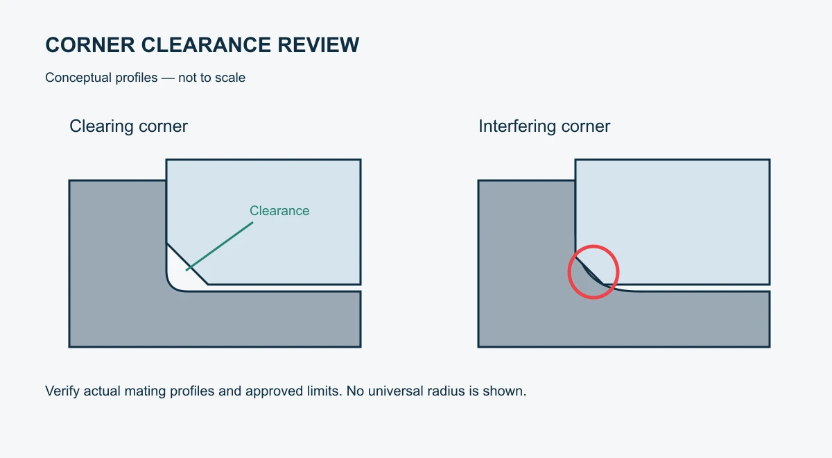
Clearance illustration only. Exact profiles and acceptance limits must come from the selected mating component and approved drawing.
7. Connect the Drawing to the Finishing Sequence
Ask how the bearing seat, shoulder face and transition reach their final condition. They may not all be finished in the same operation.
Clarify whether the specified geometry applies after heat treatment, grinding, coating and any final cleaning or polishing. Intermediate measurements can support process control without proving final compliance.
Check whether finishing access requires a relief and whether that relief is already defined. Identify surfaces that must remain protected during later operations.
If a coating affects the supporting face or fit diameter, resolve its dimensional allowance and coverage requirements before ordering. Do not assume a nominal coating description explains the final interface.
Keep manufacturing suggestions separate from approved requirements. Record accepted changes in a controlled revision or other agreed authorization before production.
8. Control Burrs Without Changing the Functional Corner
A burr can prevent seating or damage a mating surface. Removing it carelessly can also change a locating edge or intended transition.
Identify which edges require a defined chamfer, radius or other treatment. Distinguish them from nonfunctional edges covered by a general deburring note.
Avoid instructions such as “make all edges smooth” where dimensional limits matter. They leave too much room for interpretation.
Consider the intersection of grooves, keyways and shoulders. These locations may need an agreed inspection approach because access is limited.
Use the shaft deburring guide to frame the discussion. A photograph can document visible condition, but it does not prove that a controlled edge profile meets its limits.
9. Review Assembly and Removal Access
The shaft must work with the installation process as well as the final assembly. Check how the mating component reaches its seat and how the installation tool contacts it.
Confirm the bearing manufacturer's mounting instructions and the intended fit. Do not assume that a shoulder gives a suitable reaction surface for every installation method.
Review tool access around nearby diameters, threads and seals. An apparently generous gap may be inaccessible once adjacent components are installed.
Consider planned disassembly. If puller access, a spacer or another removal feature is required, define it during design rather than modifying delivered shafts.
Document the assembly assumptions shared with the supplier. They help identify conflicts without transferring responsibility for the complete machine design to the machining vendor.
10. Agree on Inspection Evidence Before Ordering
Define how critical features will be verified. The method must assess the actual requirement, not simply produce a convenient number.
For a radius or groove profile, agree on suitable access and measurement evidence. For a face requirement, confirm the datum setup. For axial location, identify the relevant reference and measurement surfaces.
An assembly check can reveal interference but does not automatically verify every dimension or geometric control. Likewise, a dimensional report may not prove the complete stack performs correctly.
Record any inaccessible or unmeasured characteristics openly. Do not let a blank report field appear to mean acceptance.
Our first-article inspection checklist explains how to connect drawing revisions, identified samples and inspection results before production release.
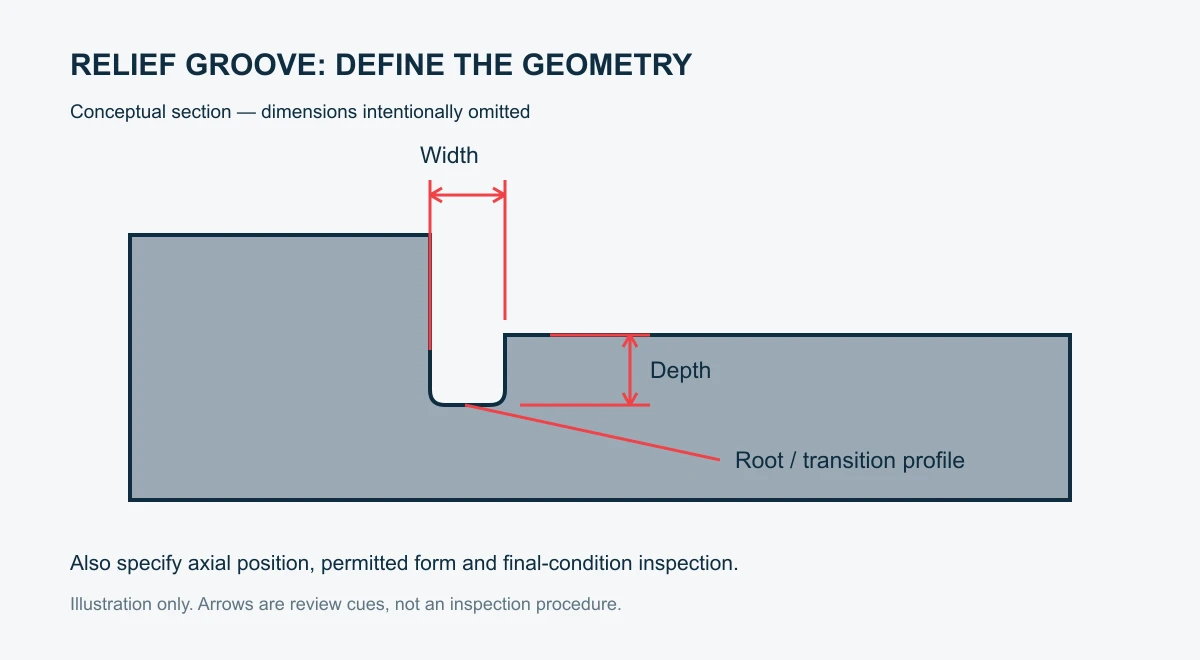
Conceptual inspection planning illustration. Arrows identify review items, not a specified measurement method or manufacturing tolerance.
11. Prepare a Complete RFQ Package
Send the current shaft drawing with the mating-component information needed to evaluate its interfaces. Include sample quantity, expected repeat demand, material and final treatment requirements.
Flag the functional shoulders and explain any critical axial stack. Provide the requested inspection-report format and required first-article evidence.
Ask the supplier to identify ambiguities, proposed manufacturing changes and inspection exclusions before quotation acceptance. Compare quotations against the same drawing revision and verification scope.
For TOPSHAFT, request confirmation of manufacturing feasibility and inspection arrangements for your specific drawing. This article does not establish a universal radius capability, a particular inspection instrument or an application load rating.
12. Keep Approval and Change Control Visible
When the first samples arrive, review the shoulder interface against the released drawing and the agreed inspection plan. Keep the sample identity linked to the report and mating-component designation.
If assembly reveals interference, first confirm that the correct parts and revisions were used. Compare the observed contact with the specified profiles before assigning the cause. A shortfall in axial seating can have several possible causes; it should not automatically trigger a smaller radius.
Record the proposed correction and the features that need reinspection. If the change affects a load-bearing transition, obtain engineering approval before accepting modified samples.
Carry the approved geometry into repeat orders. A successful hand-finished sample does not authorize an undocumented production method or a different corner form. Require notification of relevant process or component changes under the purchasing agreement.
This closes the loop between design intent, machining, assembly evidence and repeat supply. It is more useful than adding increasingly tight tolerances without understanding the original failure.
Frequently Asked Questions
Is a smaller fillet always better for bearing clearance?
No. Clearance is only one consideration. The engineer must also review the structural transition and the selected component's requirements.
Can a relief groove replace any fillet?
No. It changes local geometry and may affect the cross-section. Its suitability needs explicit design approval.
Does a correct bearing-seat diameter prove correct seating?
No. Corner interference, shoulder position and face geometry can still cause assembly problems.
Should every shoulder have the same tolerance?
No. Requirements should follow each shoulder's function, datum relationship and assembly consequences.
Can the supplier add an undercut to simplify grinding?
Only within the released requirements or an approved change. A manufacturing benefit does not authorize a design modification.
What if the bearing model changes?
Recheck the interface. The same bore diameter does not guarantee identical chamfers, abutment limits or installation requirements.
Can an illustration be used as a production drawing?
No. The illustrations here explain relationships only. Manufacture and inspection require approved drawings and specifications.
Request a Drawing-Based Review
Before ordering, connect the shaft shoulder, transition and mating component in one review. Resolve unclear geometry before it becomes a sample rejection or assembly delay.
Contact TOPSHAFT with your shaft drawing, mating-component details, material, finishing requirements and quantities. Ask for confirmation of the manufacturing route and inspection scope before placing the order.