
Visual Inspection of Precision Shafts: Surface Damage and Acceptance
A shaft passes its dimensional checks, but receiving inspection finds a line across a polished surface. One person calls it a harmless machining mark; another calls it unacceptable damage. A photograph taken under strong side lighting makes the line look severe, while a second photograph barely shows it. Without an agreed inspection method and acceptance criteria, both teams may be describing the same part yet making different decisions.
This guide explains how OEM buyers and quality teams can define a practical visual inspection agreement for precision shafts. It is not a universal scratch allowance, a repair instruction or proof that appearance predicts service life. The responsible design authority must establish application-specific acceptance. Confirm the available inspection and reporting scope with TOPSHAFT during quotation rather than assuming a particular laboratory service, instrument or certification is included.
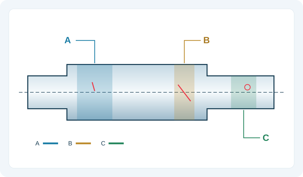
1. Separate Appearance from Other Acceptance Requirements
Visual inspection asks what can be observed under a defined procedure. Dimensional inspection, surface texture measurement, cleanliness testing and nondestructive testing answer different questions. A satisfactory diameter does not establish an undamaged surface, and a clean-looking surface does not establish subsurface integrity. Keep these requirements separate in the order so a visual pass is not presented as evidence that every other requirement has been met.
Use the surface finish specification guide for the texture requirement and the shaft NDT checklist where a separate examination is specified. Do not diagnose an indication as a crack, grinding burn or metallurgical defect from an ordinary photograph alone. Record the observation, its location and the reason for escalation; a competent review can then determine whether another method is necessary.
2. Divide the Shaft into Functional Surface Zones
Mark the drawing or a controlled sketch with identifiable zones. A bearing seat, seal track, shoulder, thread and noncontact external surface may need different instructions because they serve different functions. Define the boundaries axially and circumferentially where relevant. A note such as “good appearance required” gives little guidance about which surfaces matter or how the decision should be made.
Tie the zone map to the drawing revision and identify surfaces that will become inaccessible after assembly. For a seal-contact region, consult the actual seal manufacturer's requirements rather than importing a cosmetic rule from another area. SKF's seal counterface guidance specifically addresses surface damage and protection. That application guidance is not a universal allowance for all shaft surfaces; use the requirements applicable to the selected assembly.
3. Agree the Surface Condition Before Looking
Specify whether inspection occurs before or after cleaning, protective oil application, coating, packaging or another agreed stage. A film can obscure an indication or change reflections, while unsuitable cleaning can alter the surface. Identify an approved cleaning and handling procedure compatible with the material and finish. Do not remove a coating or use abrasive preparation simply to improve the view without authorization.
If the inspection requires temporarily removing protection, define how it is restored and who is responsible. Keep inspected parts separated from unreviewed parts and avoid creating new contact marks during handling. Coordinate the process with the shaft cleanliness checklist. Cleanliness acceptance and visual appearance remain different requirements even when they share a preparation step, and neither should be silently substituted for the other.
4. Define Viewing Conditions That Both Parties Can Repeat
Agree lighting arrangement, viewing distance, permitted magnification, coverage and any aids needed for the actual component. There is no single lighting value or magnification suitable for every order. Explain how the shaft is supported and rotated so the required accessible surfaces can be examined without losing identification or damaging a finished feature. Record limitations where geometry prevents a complete view.
Use the same agreed conditions when developing reference examples and during routine inspection. A bright reflected line can reveal a small indication, but photographs taken with unrelated exposure, angle or magnification are not automatically comparable. If a borescope or other aid is proposed, confirm its suitability and the area it can actually cover. Do not label an inaccessible region as inspected merely because adjacent surfaces were visible.
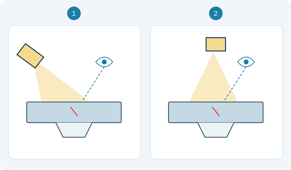
5. Describe Indications Without Guessing Their Cause
Use agreed terminology for observations such as scratches, dents, pits, discoloration, raised material or unusual marks. The ISO 8785 reference on surface imperfections provides terms, definitions and parameters; its title should not be mistaken for an order-specific acceptance limit. Identify the applicable document and edition when it is used contractually, and obtain the actual criteria from the approved drawing or inspection specification.
Describe where the indication lies, its orientation and the extent that can be established with the agreed method. Do not turn a casual visual estimate into a claimed depth measurement. If size, height or depth controls acceptance, specify a suitable measurement route and reporting basis separately. A camera image, a surface texture number and a dimensional profile are different forms of evidence; they should not be treated as interchangeable.
6. Write Acceptance Rules Before the First Dispute
The design authority should determine which indications are prohibited, which require measurement or review and which are acceptable within explicitly defined limits. Link each rule to the relevant zone and inspection stage. Avoid unsupported universal statements such as “any mark that cannot be felt is acceptable.” A tactile impression is not a documented depth measurement and can introduce contamination or damage if performed carelessly.
Where boundary samples or reference images are used, give them identifiers, revision control and a clear status. State whether they supplement written limits or govern a particular appearance judgment. Include the viewing conditions under which they were approved. A reference is useful only if both parties can retrieve the same approved example; an old phone image with unknown scale should not quietly become the acceptance standard for later orders.
7. Make Photographic Evidence Traceable
Capture an overall view that identifies the component and zone, then a closer view of the indication with suitable orientation and scale where required. Keep original files and distinguish any annotated copy from the original. Record the part or lot identity, drawing revision, inspection stage and date. If the scale or measurement method is unsuitable, do not imply that an image proves the feature's true dimensions.
Do not use contrast enhancement, cropping or selective lighting to conceal uncertainty. Annotate the observation without covering the relevant surface detail, and avoid claiming more precision than the image supports. Agree how images are named, retained and transferred, especially when several similar shafts are inspected together. The material traceability guide provides useful identification principles, but a photograph still needs a reliable link to the actual inspected part.
8. Define Coverage, Sampling and the Hold Process
State whether all parts or an agreed sample will be visually inspected, which surfaces are included and how the sample is selected. “Full inspection” should identify the specified coverage; it does not mean every possible internal or hidden condition has been assessed. Use the inspection sampling guide to connect the lot, selection rules and acceptance decisions. Do not invent a universal sample quantity without considering the order's requirements.
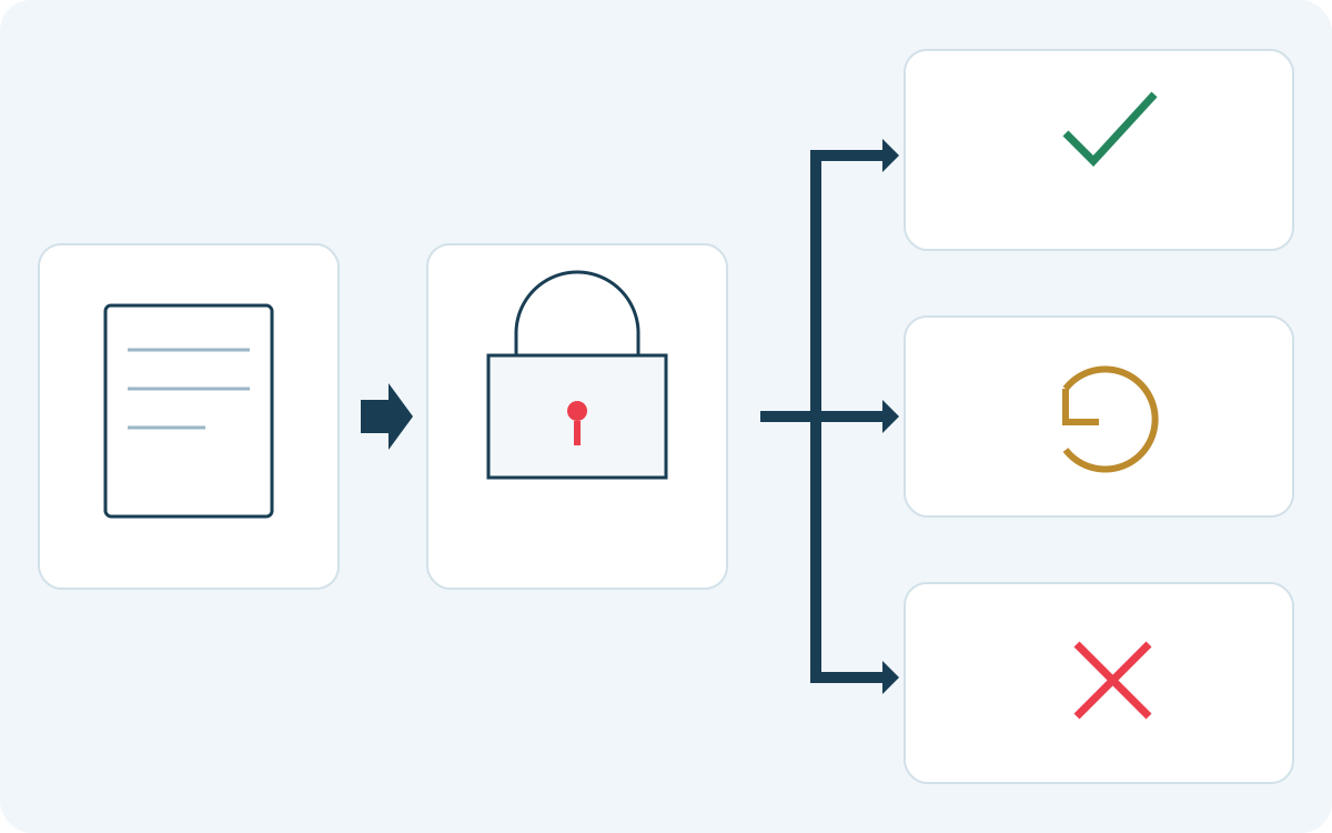
For uncertain or nonconforming observations, identify the affected parts and place them on hold under the agreed process. Record who can request additional evidence and who can authorize release, rejection or a concession. Retain the original observation even if later review changes the decision. Do not blend held parts back into accepted stock because a second observer used more favorable lighting or because the shipping deadline is approaching.
9. Use an Inspection Record That Connects the Decision
The table below is a discussion template, not a required standard or a promise of included inspection. Replace its descriptions with the order's approved instructions. A report that says only “visual OK” may omit the location, condition and authority needed to interpret the result. Ask for a sample record before ordering if a particular reporting format is necessary for your receiving process.
| Record field | What to identify | Question before release |
|---|---|---|
| Part and zone | Component identity, drawing revision and area | Which surface was actually examined? |
| Inspection condition | Preparation, process stage and viewing setup | Could the other party repeat this check? |
| Observation | Description, location and referenced images | What is observed rather than assumed? |
| Evaluation | Applicable criteria and any separate measurement | What evidence supports the decision? |
| Disposition | Reviewer, status, authorization and restrictions | Who approved the final action? |
Keep inspection findings separate from the proposed cause and corrective action. The same visible mark may require investigation before its origin is known. Record whether the evidence concerns the manufactured condition, transit condition or a condition observed after unpacking without assigning blame from timing alone. Agreement on the factual record helps both parties decide which additional checks are justified and prevents an appearance discussion from becoming an unsupported claim about the entire production process.
Before routine production, have the customer and supplier review a small set of representative examples using the proposed procedure. Include clearly acceptable examples, clearly unacceptable examples and cases that need escalation, without inventing limits from the examples themselves. Record disagreements and resolve the wording or viewing setup before treating the exercise as complete. Identify how inspectors are instructed when a reference is revised, and retire superseded images so they do not remain in informal use. For digital records, preserve the original image resolution and note whether an enlarged display is only an aid or part of the specified evaluation. This alignment exercise does not validate service performance, but it can expose interpretation gaps before they affect a shipment.
10. Control Rework and Prevent New Damage
Do not polish, blend, grind or otherwise remove an indication without an approved disposition. Such work can affect dimensions, texture, coating, local material condition or the relationship between functional surfaces. If rework is authorized, define the procedure, limits and required reinspection. A better-looking surface does not automatically demonstrate compliance. Retain before-and-after evidence and identify any revised inspection records.
After acceptance, protect the surfaces through the next operation and shipment using the agreed shaft packaging plan. Define protection removal and receiving checks so the supplier and customer evaluate a comparable condition. For a custom shaft enquiry, include the drawing, zone map, appearance criteria, viewing procedure and reporting needs together. A repeatable agreement is more valuable than an undefined promise that every shaft will look perfect under any light.
Frequently Asked Questions
Does a good roughness value mean there are no scratches?
No. The specified texture measurement and a localized visual indication are different requirements. Apply the agreed methods and criteria rather than assuming one result establishes the other.
Can a photograph determine whether a line is a crack?
Not reliably by itself. Record the indication and obtain the competent review or separately specified examination needed to determine its nature and acceptability.
Is a mark acceptable if it cannot be felt?
Not automatically. The decision depends on the surface's function and approved criteria. An informal tactile check is not a substitute for a defined measurement or acceptance rule.
May a supplier polish out a mark before shipping?
Only through an authorized process consistent with the order. Define any rework and reinspection because appearance improvement alone does not establish dimensional or functional conformity.