
Shaft Eddy Current Inspection: Define Your Requirements
Shaft eddy current inspection needs conductive material, a suitable probe arrangement and demonstrated coverage. You also need a defined acceptance basis. A signal can reflect geometry or material changes rather than a crack. Specify the examination question before accepting a passed label.
Start With The Inspection Question
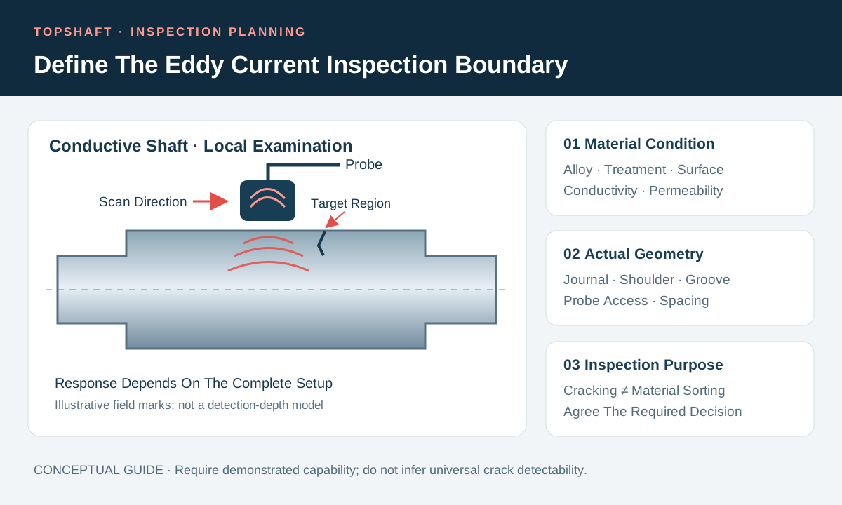
Your requirement should identify the condition that eddy current examination must investigate. Surface cracking, material sorting and conductivity measurement are different applications. A setup intended for one question does not automatically answer another. State the concern, relevant shaft features and required decision before requesting equipment or pricing.
ISO 15549:2019 establishes general principles for repeatable eddy current examination. Its scope also addresses application documents for particular products. You therefore need more than the standard's name. Identify the contractual procedure, edition and product requirements that translate general principles into your actual examination.
Keep this distinction visible during quotation. You may require crack examination after grinding, rather than material sorting before machining. The purchase description should preserve that purpose. Use your shaft NDT requirement review to identify other integrity questions. This guide supports purchasing decisions; it does not replace qualified examination instructions.
Confirm The Material And Treatment Condition
Your inspection arrangement must suit the shaft's electrical and magnetic properties. Eddy current examination induces currents within conductive material. Conductivity and magnetic permeability affect the response. Specify the alloy, heat treatment and relevant surface condition instead of describing the material simply as steel or stainless.
Evident's eddy current introduction explains how induced currents change the probe's electrical impedance. Discontinuities can alter that response, but material properties also matter. Do not interpret every difference between two shafts as damage. Confirm that the proposed setup addresses the actual material condition.
Ferromagnetic materials require particular attention to permeability effects. They are not universally excluded from every eddy current application. Equally, a successful demonstration on one alloy does not establish suitability for another. Ask the inspection organization to explain the application limits. Connect the confirmed material identity to your traceability requirements.
Keep Penetration Separate From Detection Claims
Your specification should require demonstrated examination capability rather than a universal detectable depth. Current density falls with depth. Frequency, conductivity and permeability influence that distribution. A theoretical penetration value does not establish the smallest crack that your complete system will reliably find.
Eddyfi's skin-depth explanation describes the theoretical depth where current density falls to roughly 37 percent. It also explains why increasing frequency generally reduces penetration. That definition concerns current distribution. It is not a guaranteed inspection depth, acceptance limit or direct measurement of crack size.
Ask how the selected frequencies and probe arrangement address the required discontinuities. Define the relevant locations and orientations through the approved application. Avoid copying frequencies from an unrelated shaft. If your concern involves deep internal conditions, obtain a separate technical assessment. Do not present a surface-focused examination as proof of unrestricted internal integrity.
Map Probe Access And Scan Coverage
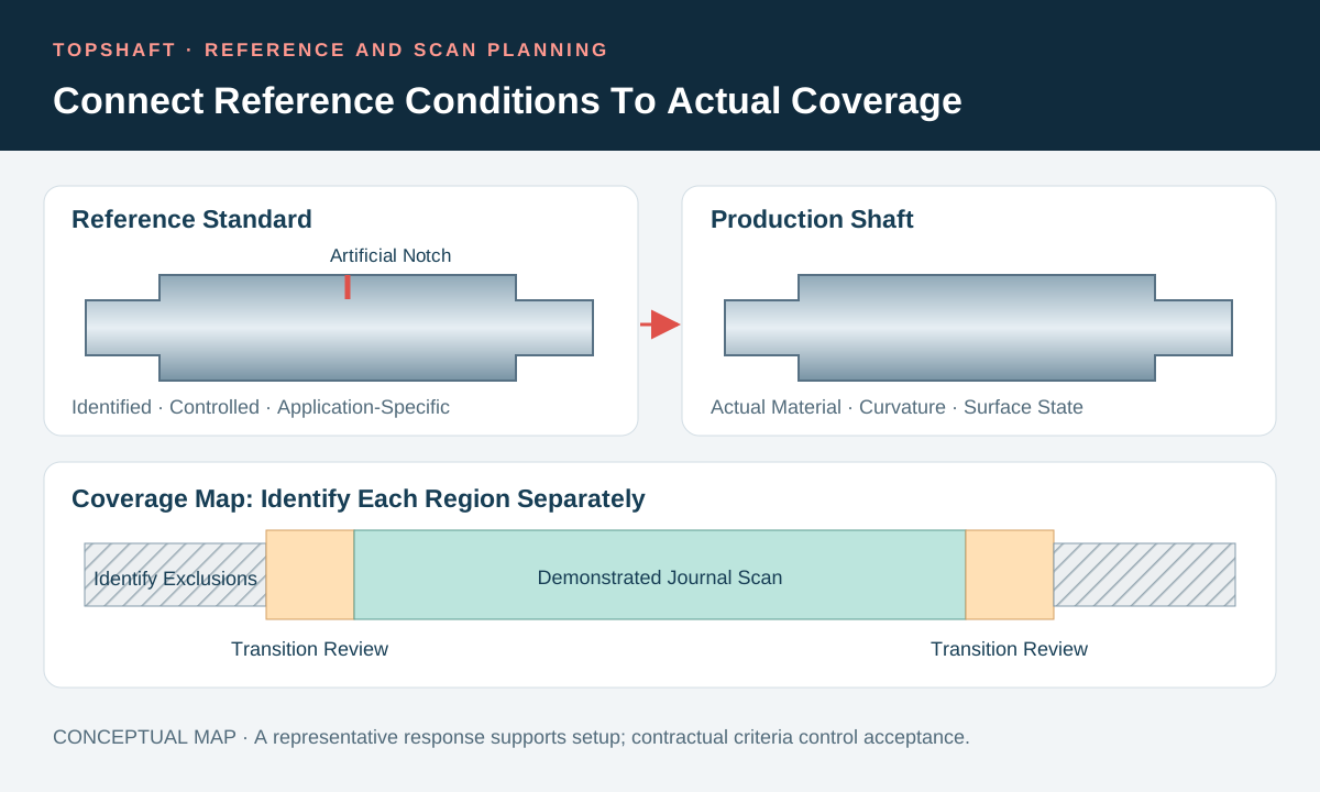
Your coverage plan should identify the surfaces that the actual probe arrangement can examine. Mark journals, shoulders, grooves, fillets and accessible bore regions individually. Identify transitions that need another probe or scan arrangement. A broad instruction covering the entire shaft can hide regions that were never demonstrated.
Distinguish moving the probe from obtaining useful coverage. The probe may reach a narrow groove without maintaining the required position. Likewise, a journal scan may stop before its shoulder transition. Require the inspection organization to identify practical exclusions. Engineering should resolve those exclusions before anyone certifies the requested examination as complete.
Separate piece selection from surface coverage. Examining every shaft does not establish that every required surface received suitable examination. Conversely, a complete scan of selected pieces does not automatically justify a whole-lot statement. Record the examined population, feature map and agreed sampling basis. Keep requested and actual coverage distinguishable in the report.
Control Lift-Off Geometry And Surface Condition
Your procedure should control probe spacing and geometry effects that can obscure the required response. Lift-off describes separation between the probe and examination surface. Coatings, probe wear protection and changing contact can affect that spacing. A signal change therefore needs interpretation within the controlled setup.
The US Air Force NDT technical manual discusses lift-off, permeability and geometry effects. Edges and abrupt section changes can produce responses unrelated to cracks. These effects matter around shaft shoulders and grooves. Ask how the procedure distinguishes relevant findings from these competing responses.
Identify the actual coating and surface state during qualification and production examination. Do not assume inspection through a coating is always acceptable or always impossible. The inspection organization must establish suitability. Review proposed coating removal or polishing against your surface finish requirements. Preparation must preserve controlled dimensions and functional surfaces.
Agree A Representative Reference Standard
Your reference standard should support the demonstrated application rather than merely produce a convenient signal. Identify the required material, geometry and artificial discontinuity characteristics through the governing procedure. Keep its unique identification and condition controlled. A reference response alone does not establish the acceptance rule for production shafts.
NASA's eddy current process specification illustrates application-specific controls for reference standards and scanning. Its requirements belong to its stated scope. Do not transfer its notch dimensions or operating limits automatically to a commercial shaft. Use the contractually applicable documents and responsible technical authority.
Discuss differences between the reference and production geometry before examination. A flat reference may require justification for a curved journal application. Likewise, an artificial notch is not a complete model of every natural crack. Ask what the demonstration establishes and where limitations remain. Preserve that explanation with the approved inspection arrangement.
Verify The Complete Examination System
Your verification plan should cover the instrument, probe, connections and application arrangement together. An instrument calibration certificate does not demonstrate coverage of your shaft. Identify the required functional checks, reference responses and permitted changes. Define how the inspection team responds when a check fails.
ISO 15548-2:2013 addresses probe characteristics and their verification. Its scope leaves verification extent and acceptance criteria to application documents. Specify those requirements through the applicable procedure. Confirm contractual personnel qualification and approval responsibilities separately. Neither a probe model nor a general training claim establishes every required authorization.
Ask which changes trigger another check or technical review. Probe replacement, altered spacing or changed scanning arrangements may affect the approved application. Keep affected pieces identifiable if performance becomes uncertain. Establish the required re-examination decision through the procedure. Do not let receiving staff decide retrospectively which earlier results remain valid.
Define Scanning For Your Production Volume
Your scanning arrangement should maintain the required coverage under actual production conditions. Manual, rotating and array arrangements have different practical implications. Choose between them through geometry, required response and demonstrated control. Production volume affects the commercial choice, but speed must remain compatible with the examination requirements.
Eddyfi's array overview describes multiple elements covering a wider area than a single-coil probe. Wider nominal coverage does not remove application limits. Confirm the active inspection width, required overlap and applicable orientations. Do not infer complete shaft coverage from the overall dimensions of the probe housing.
For repeat orders, identify fixtures, indexing and records needed to reproduce the arrangement. Clarify whether scan position is recorded or established by another controlled method. Specify any required retained data and file compatibility. A colorful coverage display needs identifiable axes, locations and interpretation. It should support the inspection decision rather than serve as decoration.
| Requirement | Buyer Decision | Evidence To Retain |
|---|---|---|
| Inspection purpose | Cracking, sorting or another defined application | Approved scope and procedure |
| Material condition | Alloy, treatment and relevant surface state | Traceable material and process identity |
| Coverage | Features, orientations, selected pieces and exclusions | Actual scan map and piece identities |
| System performance | Reference standard and functional checks | Identified reference and check results |
| Acceptance | Applicable recording and rejection rules | Findings and authorized evaluation |
| Release | Required final condition and report package | Final checks and release responsibility |
Separate Indications From Acceptance
Your acceptance decision should compare interpreted findings with the governing requirements. A signal is evidence for evaluation, not an automatic rejection. Define recording thresholds and acceptance criteria where the contract distinguishes them. Avoid asking an inspector to invent missing limits after examination has started.
Specify who evaluates uncertain findings and authorizes follow-up. Do not convert signal amplitude directly into crack depth without an applicable validated basis. Preserve reported locations and the actual interpretation. Further examination may answer a different question. Engineering should define that question rather than ordering repeated tests until one produces a favorable label.
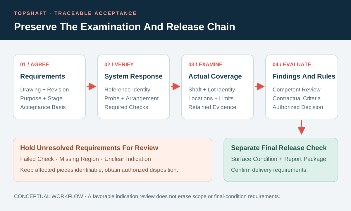
A hypothetical shaft illustrates the purchasing risk. Your order requires a shoulder transition, but the report identifies journal coverage only. Keep the unexamined transition visible. Request the missing examination or an authorized alternative disposition. A passed journal result cannot silently expand to the shoulder. This example describes a review problem, not a TOPSHAFT customer case.
Connect The Result To Manufacturing And Release
Your report should identify the manufacturing stage represented by the examination. State whether relevant machining, heat treatment or coating remains afterward. Earlier examination does not automatically represent the final surface. Define any further verification through the responsible authority when subsequent processing changes the condition under review.
Record the part number, drawing revision, lot and individual identity where required. Include the procedure revision, equipment references, reference standard and actual coverage. Retain required findings, exclusions and authorized departures. Connect the report to delivered pieces. A disconnected image or generic certificate cannot establish that relationship by itself.
Confirm the delivered surface condition independently where required. Remove temporary markings or protection only through approved instructions. Manage corrections through your rework and concession process. Preserve original findings and authorized conclusions. A later favorable report should not erase the history behind an accepted correction.
Prepare A Confirmed TOPSHAFT Inquiry
Your inquiry should allow TOPSHAFT to confirm a feasible examination arrangement before accepting the supply requirement. Send the released drawing, material specification, treatment condition and quantities. Identify inspection purpose, required features, manufacturing stage and acceptance documents. Include annual demand, sampling expectations and reporting needs. Mark unresolved technical decisions clearly.
This article does not establish particular TOPSHAFT eddy current equipment, personnel qualifications or testing services. Confirm any proposed internal or external arrangement during quotation. Ask who approves the procedure and evaluates findings. Keep technical acceptance responsibilities separate from commercial scheduling. A general educational article cannot establish a part-specific inspection commitment.
Scope drives cost and scheduling. Access, representative standards, fixtures, selected quantities, data retention and reporting all affect the arrangement. Avoid unsupported unit prices or turnaround promises. Use your shaft RFQ checklist to assemble a consistent package. Reconfirm the arrangement when material, geometry, surface condition or contractual requirements change.
Frequently Asked Questions
Your purchasing answers should follow the demonstrated application and contractual acceptance basis. These boundaries help you interpret proposals without replacing qualified examination instructions.
Can Eddy Current Inspection Examine Nonconductive Shafts?
Conventional eddy current examination requires conductive material. Do not assume the method applies to a nonconductive shaft. Ask engineering to select suitable evidence for the actual material and failure concern.
Are Ferromagnetic Shafts Always Excluded?
No universal exclusion applies to every eddy current application. Permeability effects complicate the response and need application-specific control. Obtain confirmation for your exact material, condition and examination purpose.
Does Skin Depth Define The Detectable Crack Depth?
No. Skin depth describes theoretical current distribution. Detectability depends on the complete application, including material, geometry, discontinuity orientation and system performance. Require demonstrated capability rather than substituting a theoretical number.
Can You Inspect Through A Coating?
Possibly, when the approved arrangement demonstrates suitability for that coating and spacing. Identify its material, thickness and condition. Do not assume a setup qualified on bare material transfers unchanged.
Does A Reference Notch Define Rejection Automatically?
No. The reference supports system setup or evaluation under the applicable procedure. Your acceptance rule must come from the governing requirements. Resolve missing criteria before production examination.
Does Every Shaft Passing Mean Complete Surface Coverage?
No. Piece selection and feature coverage are separate requirements. Verify the actual scan map and exclusions. Keep unexamined regions visible instead of extending a result beyond its recorded scope.
Can Eddy Current Replace Every Other NDT Method?
No. Each method addresses particular conditions and limitations. Select complementary evidence through the actual engineering concern. Avoid treating one favorable surface examination as unrestricted proof of internal integrity.
What Should You Send For A Quote?
Send the drawing, material condition, required regions, examination stage, governing documents, acceptance reference and quantities. Include reporting and approval responsibilities. Ask for explicit confirmation of scope and limitations.
Send Your Inspection Requirements
You can reduce ambiguity by agreeing material suitability, coverage, reference standards and acceptance before examination. Contact TOPSHAFT with your drawing and inspection package. Request confirmation of the proposed arrangement, report contents and final release responsibilities.