
Shaft Alignment Requirements: What OEM Buyers Should Specify Before Assembly
A precision shaft can pass dimensional inspection and still run in a misaligned machine. The shaft drawing describes the component. It does not, by itself, establish the relationship between the driving and driven machines after installation.
For OEM buyers, that distinction matters. Bearing journals, coupling seats and shoulders may meet their requirements while the assembled shaft axes remain incorrectly positioned. Before attributing an operating problem to the shaft supplier, distinguish component geometry from assembly alignment.
Start by identifying the axes that must be aligned. Then define the machine configuration, measurement conditions, acceptance criteria and party responsible for final verification. Keep these requirements separate from the shaft's dimensional inspection report.
This guide explains what belongs on the shaft drawing, what belongs in the assembly specification, and what evidence you should request before accepting the completed equipment.
1. Shaft Geometry Is Not Machine Alignment
A shaft drawing can control journal diameter, straightness, roundness, shoulder position and runout relative to specified datums. These requirements govern the manufactured part. Machine alignment concerns the relative position and direction of the rotational axes in the installed assembly.
Do not substitute one report for the other. A journal runout result does not establish whether a motor and pump are aligned. Equally, a satisfactory alignment result does not prove that every journal or coupling seat meets its drawing tolerance.
Separate the acceptance records into component inspection and assembly verification. If an issue appears during testing, this separation helps you investigate the correct interface instead of repeating an unrelated measurement. Our shaft runout guide explains why the datum and measurement setup matter when inspecting an individual shaft.
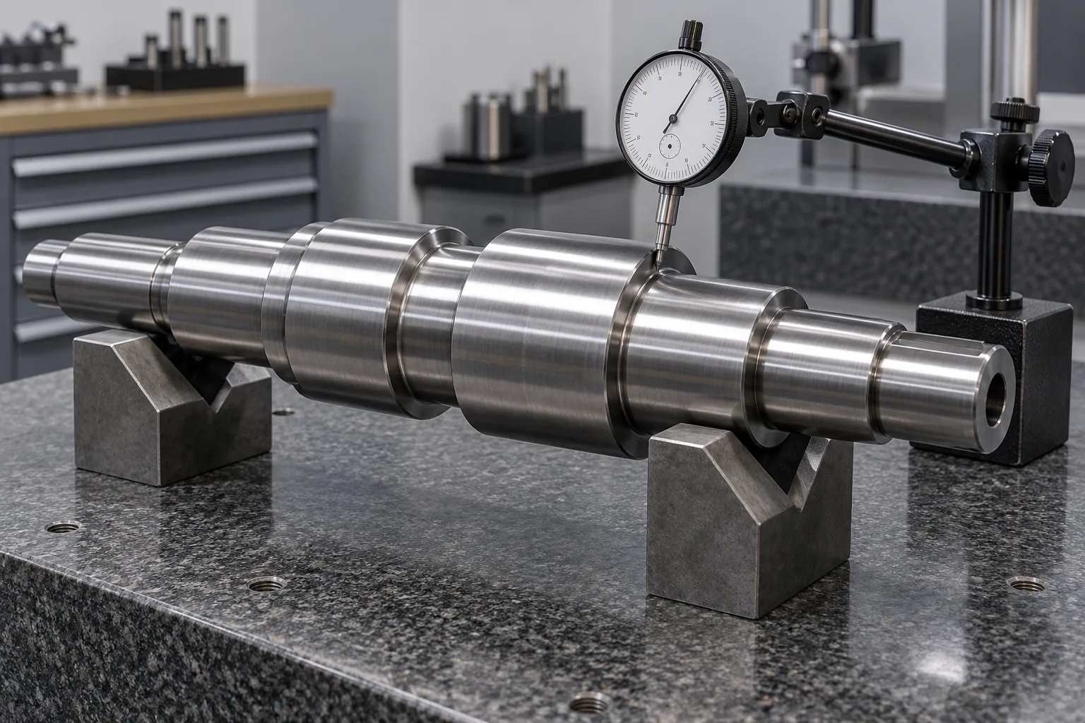
AI-generated illustration of component inspection. It is not a prescribed measurement setup, a photograph of TOPSHAFT equipment or an actual inspection result.
2. Understand Offset and Angular Misalignment
Offset misalignment describes a positional difference between the axes at a defined reference plane. Angular misalignment describes a difference in their directions. Both can occur in the same assembly, and each can have horizontal and vertical components.
The reference plane and units are important. An offset reported at the coupling center is not automatically the same as a measurement taken elsewhere. Angular results may be expressed as a slope, angle or coupling-gap relationship. A number without its definition is not a usable acceptance criterion.
Ask the assembly team to identify the reference plane, sign convention and units in the report. Avoid comparing results that use different definitions. If the measurement software calculates movement at the machine feet, distinguish those correction values from the remaining alignment error at the coupling.
SKF's technical explanation of foot correction connects angular and parallel misalignment to machine-foot adjustments. A proposed adjustment is not itself proof of the final condition; the assembly still needs verification after correction.
3. Define the Equipment Configuration First
Before asking for a tolerance, identify the equipment being accepted. Specify the driving and driven machines, coupling type, relevant operating speed, mounting arrangement and measurement access. Record which machine is considered fixed and which can be moved.
For equipment with more than two machines, define the complete train rather than treating every coupling as an isolated pair. An adjustment at one interface can affect another. The verification procedure must reflect the installed configuration.
The coupling manufacturer's allowable misalignment is not automatically the equipment's alignment target. Coupling limits and machine acceptance criteria serve different purposes. Use requirements approved for the actual equipment, operating conditions and installation. Do not adopt a universal limit from a different assembly simply because its shafts have similar diameters.
If acceptance criteria have not been established, mark them as an engineering decision before ordering the assembly. Do not leave the supplier to infer them from the word “precision.”
4. Keep Component and Assembly Requirements Separate
On the shaft drawing, define the functional journals, coupling seat, axial locating faces, keyways or splines, material condition and inspection datums. Identify the features that position the mating parts. Avoid tightening every dimension without a functional reason.
In the assembly specification, define the alignment targets, reference plane, measurement condition, procedure and responsibility. State whether verification takes place before shipment, after site installation, or at both stages. These are different acceptance events.
Include drawing revisions and equipment identifiers in both records. For example, a coupling-seat inspection should be traceable to the shaft drawing, while the alignment record should identify the machines and coupling installed during measurement.
Review the coupling shaft-end specification guide when defining the mating interface. A correct shaft-end fit supports assembly, but it does not replace final alignment verification.
5. Check Mounting Conditions Before Correction
An assembly needs a stable mounting condition before its alignment results can be interpreted confidently. Ask the responsible team to review the base, machine feet, fasteners and approved mounting procedure. A measurement taken before the required connections are complete may not represent the accepted configuration.
Soft foot refers to a support condition in which a machine foot does not seat correctly under the relevant fastening condition. This can affect the machine's position when bolts are tightened. It should be assessed by trained personnel using the equipment's approved procedure, not treated as an unexplained alignment error.
For connected equipment, external loads may also matter. Piping or other attachments can influence machine position. Establish which connections must be complete before final measurement and whether a repeat check is required after their installation.
Do not prescribe arbitrary shim thicknesses or bolt-loosening sequences in a purchasing note. Ask for the mounting checks to be documented and for adjustments to follow the applicable equipment instructions.
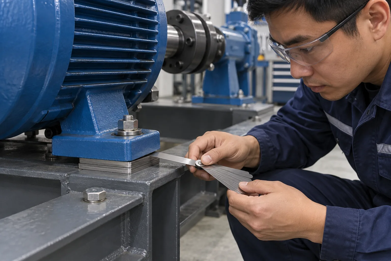
AI-generated illustration of a mounting-condition check. The image is not an installation procedure or evidence of actual TOPSHAFT personnel.
6. State Cold and Operating Targets Clearly
A stationary, cold machine does not necessarily have the same geometry as a running machine. Temperature changes can alter the relative position of connected equipment. Where this matters, the equipment designer should establish the required offline target and its relationship to the operating condition.
Do not assume that zero measured offset under every condition is the intended result. If a nonzero cold target is required, document its value, direction, reference plane and engineering basis. Otherwise, an installer could adjust away an intentional allowance.
Record the condition of the equipment during measurement. Identify temperatures or operating history when these are part of the agreed procedure. If hot-condition checks are required, they must follow the equipment's safety and measurement instructions; this article is not a procedure for approaching running machinery.
The SKF machine-train alignment instructions include target values and thermal-growth considerations. The relevant target for your purchase still needs approval for your specific assembly.
7. Agree on Measurement Method and Access
Select a method suitable for the equipment and required acceptance criteria. Depending on the assembly, the approved procedure may use laser alignment or dial-indicator techniques. The instrument alone does not define the validity of the result.
Review mounting access, measurement distances, shaft rotation constraints and the reference locations before equipment reaches inspection. Guards, short exposed shaft sections or limited movement can affect how the measurement is performed.
Ask the team to record the instrument identity, applicable calibration status, setup and measurement condition. If a different method is proposed, confirm how its results will be evaluated against the same acceptance requirements. Avoid comparing screenshots without understanding their underlying setup.
Require a repeat measurement after the adjustment and final fastening steps specified by the procedure. When the setup changes, retain enough information to explain why the second result represents the final assembly.
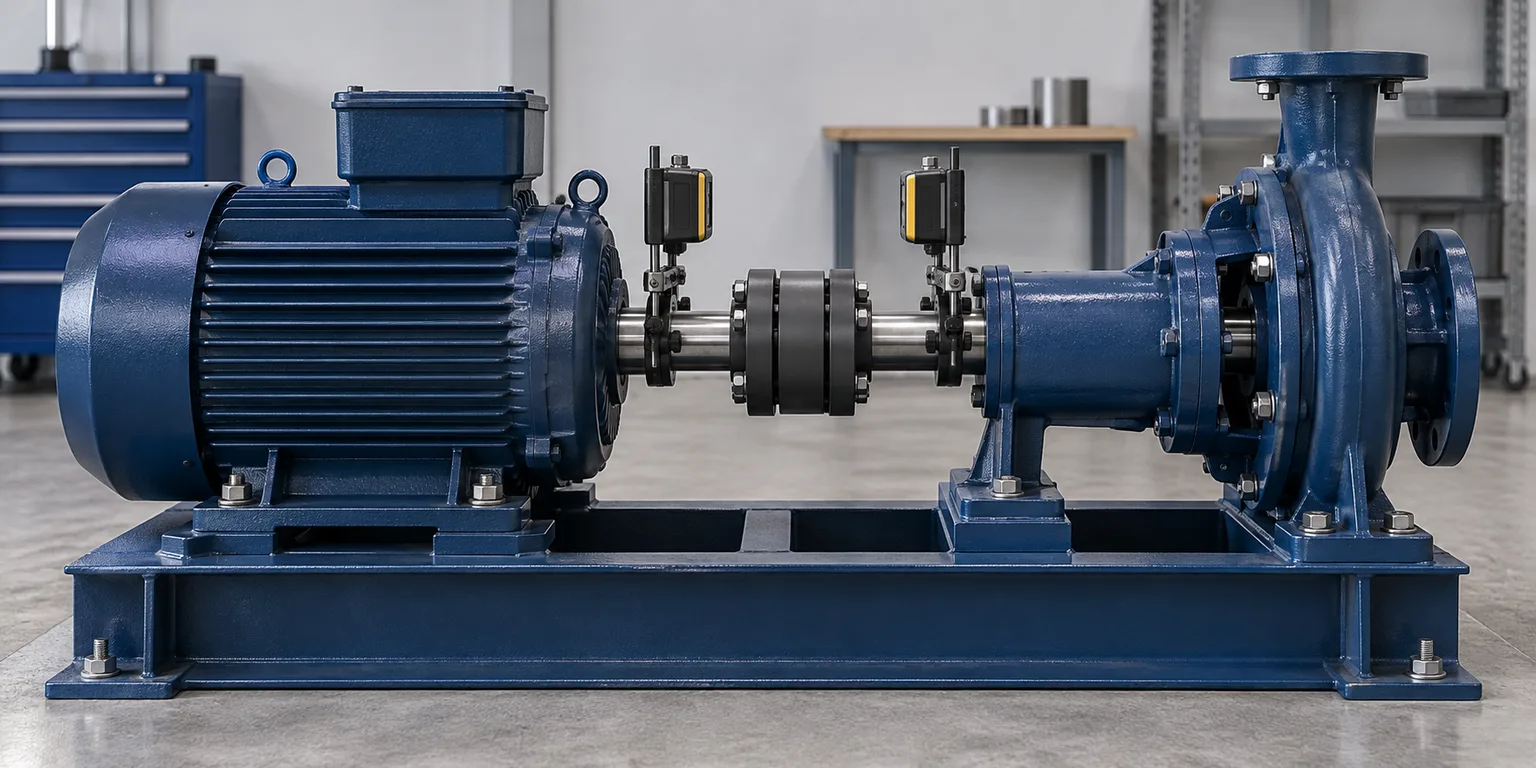
AI-generated illustration of a stopped assembly prepared for alignment measurement. It is not a photograph of an actual TOPSHAFT installation.
8. Request a Useful Alignment Report
A report should help another engineer understand what was accepted. A green indicator or the phrase “alignment passed” is insufficient if the criteria and equipment condition are missing.
Request the machine identifiers, coupling identity, measurement date, operator, instrument, units and reference plane. Include the approved tolerance or target, the initial results, the final results and any applicable mounting checks.
Keep correction values separate from acceptance values. Adding shims or moving a machine by a calculated amount does not guarantee that the final measured result equals the target. The final report should show the measured condition after the agreed adjustments.
Where photographs are useful, show the sensor mounting and equipment arrangement. They support interpretation but do not replace the numerical results. Retain the report with the relevant assembly revision so that later service work has a meaningful baseline.
9. Assign Responsibility Before the Purchase Order
Custom shaft manufacture and machine installation may involve different companies. Define who supplies the shaft inspection report, who assembles the mating components, who performs alignment and who approves the acceptance criteria.
If the equipment builder provides a factory alignment report, clarify what must be checked again after transport or site installation. A factory result describes the measured configuration at that stage. It should not be presented as verification of a later installation that has not been measured.
For troubleshooting, agree on an evidence sequence. Review the reported symptom, component records, mounting condition and alignment results before deciding that a replacement shaft is required. This approach keeps responsibility tied to verified findings rather than assumptions.
A commercial requirement such as “supplier responsible for alignment” needs a defined scope. Specify location, equipment, acceptance event and deliverable. Do not assume a shaft quotation includes field installation services.
10. OEM Review Checklist
Before releasing the assembly for manufacture or installation, confirm these items:
- Current shaft and assembly drawing revisions are identified.
- Functional journals, coupling seats and axial locations are defined.
- Driving machine, driven machine and coupling configuration are recorded.
- Fixed and movable equipment are identified.
- Alignment reference plane, units and sign convention are stated.
- Approved tolerances and any cold targets are documented.
- Mounting checks and required connections are included in the procedure.
- Measurement method, access and instrument requirements are agreed.
- Final verification occurs at the specified fastening and assembly condition.
- Factory and site acceptance responsibilities are assigned separately.
- Required records are linked to the equipment and purchase order.
Use this checklist to find missing decisions, not to impose the same requirements on every machine. The responsible engineering team should select the controls relevant to the actual equipment.
Frequently Asked Questions
Does acceptable shaft runout prove correct machine alignment?
No. Runout assesses a feature relative to its specified datum and measurement setup. Machine alignment assesses the relationship between installed rotational axes. Both may be relevant, but they require separate evidence.
Can a flexible coupling replace alignment verification?
Do not assume so. Use the equipment's approved alignment criteria alongside the coupling manufacturer's requirements. A coupling's ability to accommodate some misalignment is not a general acceptance rule for the complete machine.
Is there one alignment tolerance for every precision shaft?
No universal value is proposed here. Select the criteria for the equipment configuration and operating conditions, with approval from the responsible engineering team. State the units and reference plane with the limits.
Should alignment be checked after shipment?
Follow the agreed installation and acceptance plan. If the equipment is repositioned, reassembled or connected differently at site, a factory report alone does not demonstrate the new configuration. Define the required site verification before purchase.
What should I send with a shaft RFQ?
Provide the shaft drawing, mating-interface details, material and treatment requirements, quantity and component inspection expectations. Add assembly context where it affects the shaft features. Use the precision shaft RFQ checklist to prepare the package.
Prepare the Shaft and Assembly Requirements Together
Send TOPSHAFT your shaft drawing and explain the bearing, coupling and axial-location interfaces that matter. Identify the component characteristics requiring inspection and the documents you expect with delivery.
Keep machine alignment as an explicit assembly requirement with an assigned owner. Any additional service or verification scope should be confirmed during quotation rather than assumed. Start a drawing-based inquiry with both the part requirements and the relevant assembly context.