
How To Specify A Shaft End For A Coupling: Fits, Engagement And Inspection
Your coupling shaft end needs more than a diameter and keyway. Specify the hub connection, fit, engagement, axial location, surface condition and inspection references together. This guide helps you prepare a drawing that your shaft supplier and assembly team can interpret consistently.
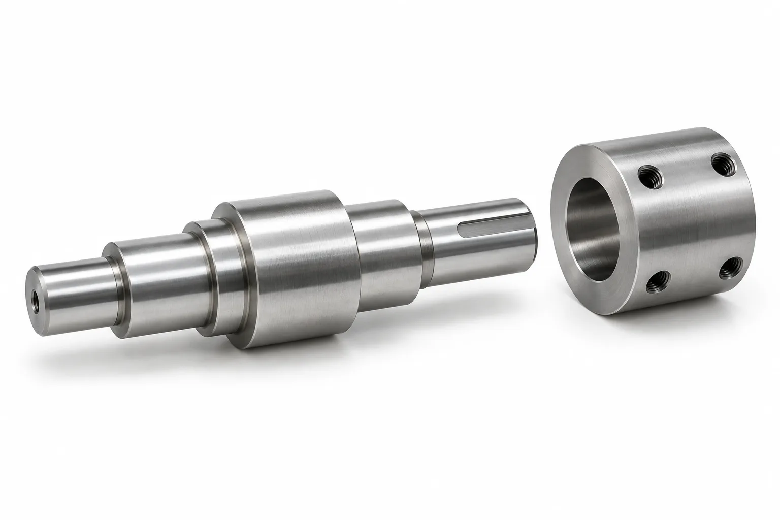
AI-generated illustration of a generic shaft–hub interface. Not a TOPSHAFT customer component or facility photograph.
Identify The Coupling And Hub Connection
Specify the selected coupling and hub connection before defining the shaft end.
Start with the manufacturer's exact coupling model, hub size and bore option. Include its drawing and relevant installation instructions. A coupling family name alone may leave several connection options unresolved.
Your shaft can connect through a key, split clamp, locking assembly, interference fit or another approved arrangement. These connections do not share one universal shaft tolerance. Their assembly methods and surface requirements can also differ.
For example, KTR's CLAMPEX description explains a frictional shaft–hub connection without a keyway. Clamping screws move wedge-shaped components, generating radial force. This illustrates why a keyed-shaft specification cannot automatically cover a locking assembly.
Do not treat the coupling's published torque rating as automatic approval of your shaft end. Check the complete connection against your operating conditions. Include nominal torque, peak torque, reversing duty, speed and relevant axial loading.
| Connection | Drawing Decisions | Assembly Questions |
|---|---|---|
| Keyed hub | Diameter fit, keyway geometry, axial retention | How is the key fitted and the hub retained? |
| Split-clamp hub | Diameter, surface condition, permitted contact zone | What tightening sequence and screw torque apply? |
| Locking assembly | Shaft tolerance, contact length, hub compatibility | Which cleanliness and lubrication instructions control? |
| Interference-fit hub | Interference limits, material, geometry | How will assembly and later removal be performed? |
Keep manufacturer-controlled requirements attached to the purchase specification. Resolve any conflict between those instructions and your drawing before quotation.
Specify The Shaft–Hub Fit
Define the shaft diameter tolerance together with the mating hub bore requirements.
A nominal diameter only describes the intended size. It does not establish clearance or interference. You need the shaft limits and the hub limits to understand the possible assembled condition.
Avoid copying a familiar bearing-seat tolerance onto the coupling end. A bearing journal and coupling seat serve different interfaces. Their functional requirements can differ, even when their nominal diameters match.
When you use a tolerance designation, identify the governing system and drawing convention. Alternatively, provide explicit limits where your engineering procedure requires them. Keep the hub specification consistent with that choice.
Review the material pair and service environment. Temperature changes can alter the assembled relationship between dissimilar materials. Thin-walled hubs and hollow shafts may also need additional engineering review.
For a frictional connection, surface condition belongs to the fit specification. Roughness, coatings, contamination and assembly preparation can affect its behavior. Follow the selected manufacturer's instructions rather than assuming every connection needs a dry surface.
Likewise, do not prescribe a polishing process without a functional reason. A visually bright seat does not establish dimensional accuracy. Specify the required finish and inspection method instead.
If you need a separate bearing seat, use the bearing journal specification guide. Keep its acceptance requirements distinct from the coupling seat.
Avoid An Unnecessary Whole-Shaft Tolerance
Apply precision requirements to the surfaces that locate or transmit load.
Tightening every diameter increases manufacturing and inspection work. It may add no value to the coupling interface. Separate functional seats from clearance diameters and noncritical surfaces.
Tell your supplier which dimensions are assembly-critical. This supports practical process planning without weakening your required fit.
Define Engagement Length And Axial Position
Specify effective hub engagement and axial location independently from the shaft's overall length.
The available shaft extension is not always the usable contact length. Chamfers, reliefs, keyway runouts and recessed hub features can reduce effective engagement.
Identify the intended contact zone on your assembly drawing. Confirm the minimum engagement using the selected coupling's requirements and your connection design. Do not invent a generic engagement-to-diameter ratio.
Define where the hub stops. It may locate against a shoulder, spacer or an independently controlled assembly dimension. A shaft end face should not become an unintended stop inside the coupling.
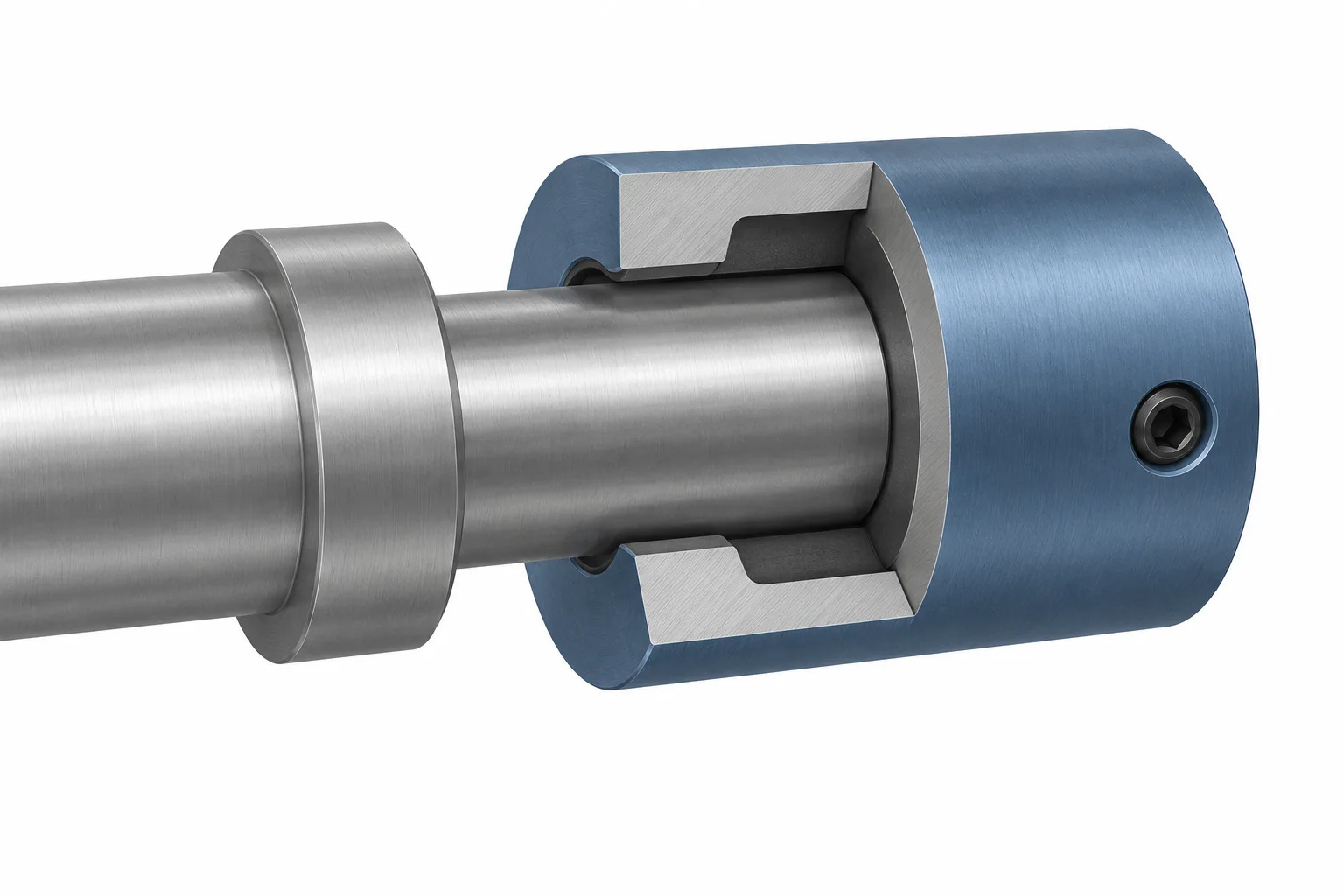
AI-generated conceptual illustration. Engagement, shoulder clearance and retention must follow your approved assembly drawing.
Review shoulder fillets against the hub's entrance geometry. A hub can appear seated while actually contacting a shaft radius. This changes axial position and may prevent the intended contact arrangement.
Include lead-in geometry that supports assembly without damaging the bore. Specify chamfers and edge condition clearly. Keep chamfers outside the required functional contact region where necessary.
You also need an axial retention strategy. A key does not automatically retain the hub axially. Depending on the design, retention may involve clamping, an end fastener, a shoulder or another approved feature.
For two connected machines, distinguish hub position from coupling assembly spacing. The required gap or spacer arrangement belongs to the coupling installation design. It is not necessarily equal to the distance between shaft ends.
Review The Axial Stack
List the dimensions that determine the hub's final location.
Include the bearing reference, shaft shoulder, spacer thickness, hub length and retained position. Identify which dimensions are manufactured and which are adjusted during assembly.
Then consider their tolerance accumulation. Checking each dimension separately does not prove the complete stack will assemble correctly. Use your engineering tolerance analysis to confirm the final arrangement.
Coordinate Keyways And Clamping Surfaces
Specify connection features so they support the selected hub rather than interrupting its working surfaces.
For a keyed hub, define the keyway width, depth, length and position. State the governing standard where applicable. Confirm whether your purchase includes the key or only the machined shaft.
Keyway length and key length are different dimensions. Cutter runout or rounded ends can limit the usable region. Coordinate that region with the hub's keyway and intended engagement.
Specify acceptable burr removal without rounding functional edges excessively. A burr can obstruct assembly or mark the mating bore. An uncontrolled edge break can also change the intended key contact.
Use the shaft keyway specification guide for the detailed drawing checklist. Keep your coupling-specific axial location requirements on the assembly drawing.
For a clamp or locking assembly, confirm whether grooves, flats or keyways are permitted within its contact region. Do not add a keyway simply because another shaft design used one.
If your design includes a setscrew, define its intended contact feature. Avoid relying on an unspecified screw point to establish repeatable positioning. Review local marking and maintenance requirements with your engineering team.
Finally, coordinate coatings and corrosion protection. State whether the coupling seat is coated, masked or protected temporarily. Distinguish shipping protection from the surface condition required during assembly.
Separate Shaft Geometry From Machine Alignment
Control shaft geometry on the component drawing and machine alignment through the installation procedure.
A coupling seat can meet its diameter limits yet run eccentrically to the bearing reference. Conversely, an accurate shaft does not guarantee that two installed machines are aligned.
Identify the functional datum system before specifying runout. Your inspection reference should represent how the shaft is located in service. Do not choose an accessible but functionally unrelated surface merely for inspection convenience.
Decide whether radial runout, face runout or another geometric control addresses the actual requirement. These controls are not interchangeable. State the inspected surface and reference clearly.
The precision shaft runout guide explains this distinction further. Avoid adding a tight runout callout without a defined reference and verification method.
Flexible couplings do not remove the need for alignment. Their permitted misalignment is model-specific and operating-condition dependent. Follow the current installation instructions for your selected unit.
SKF's alignment discussion links shaft alignment with machine reliability. Its historical article provides context, not current acceptance limits for your coupling.
For higher-speed applications, ask whether balancing requirements apply to the shaft, hub or complete assembly. Do not assume component runout inspection establishes assembled balance. Your engineering specification should identify the required condition and acceptance criteria.
Plan Machining And Inspection
Plan finishing and inspection around the shaft's final material condition and functional references.
Heat treatment and finishing can influence the manufacturing sequence. Your supplier needs to know whether dimensions apply before or after treatment. Coatings may also require allowance or masking.
Discuss the coupling seat alongside the bearing seats during drawing review. Their geometric relationship can affect setup choices. A coherent datum scheme helps the supplier plan machining and verification.
The CNC turning and features page provides related process information. Specific feasibility still depends on your material, geometry and drawing requirements.
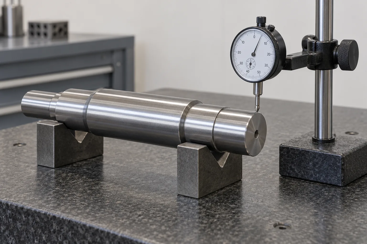
AI-generated inspection illustration. Actual fixtures, instruments and acceptance methods must suit the drawing.
| Requirement | What To Agree Before Production |
|---|---|
| Seat diameter | Limits, measuring locations and final surface condition |
| Engagement zone | Usable length, excluded chamfers and reliefs |
| Keyway | Width, depth, position and usable length |
| Runout | Datum setup, inspected surface and acceptance limit |
| Axial location | Reference face, shoulder position and stack requirements |
| Surface condition | Roughness, coating status and edge requirements |
Do not rely on a single diameter reading to characterize the entire seat. Agree representative measuring locations where geometry makes this necessary. Match the measuring method to the required tolerance.
A trial assembly can help confirm compatibility with an approved mating hub. However, it does not replace specified dimensional or geometric inspection. Document what the trial checks and what remains separately verified.
For repeat orders, identify the drawing revision and inspection requirements. Agree which records accompany shipment. The inspection and quality page explains TOPSHAFT's drawing-based approach.
Prepare The RFQ Package
Send the component drawing, mating-hub information and operating requirements together when requesting a quotation.
Include the material grade, treatment condition and required quantity. Add expected repeat volume where known. Highlight the coupling seat, functional datums and any customer-specific acceptance requirements.
Supply the coupling model and installation document revision. Include the assembly drawing when shoulder position, spacing or retention affects the shaft end. Flag unresolved requirements rather than leaving suppliers to assume them.
Cost depends on more than the nominal seat diameter. Tight geometry controls, finishing operations, special fixtures and inspection records can affect the quotation. Unnecessary requirements can increase cost without improving the interface.
Use the precision shaft RFQ checklist to organize your files. Request a manufacturing review, not an unsupported guarantee of coupling performance.
TOPSHAFT can review the shaft manufacturing requirements against your supplied drawing. Final connection selection and assembly approval remain with the responsible engineering team.
Frequently Asked Questions
Your selected coupling instructions and approved drawing should control the final shaft-end specification.
Is One Shaft Tolerance Suitable For Every Coupling?
No. The required tolerance depends on the hub connection and manufacturer's requirements. Check both shaft and bore limits.
Does A Key Retain The Hub Axially?
Not automatically. Specify a separate retention arrangement unless the approved connection design already provides it.
Can I Use The Entire Shaft Extension As Engagement Length?
Only if the complete length provides usable contact. Exclude chamfers, reliefs and other noncontact regions as required.
Must A Clamping Seat Always Be Dry?
No universal rule applies. Follow the selected manufacturer's surface preparation and lubrication instructions for each relevant interface.
Does A Flexible Coupling Eliminate Alignment Work?
No. Follow its model-specific installation and alignment requirements. Permitted misalignment is not a general installation target.
Should I Inspect Runout From The Shaft End Face?
Only when your datum scheme requires that reference. Use the functional locating references defined by the drawing.
Can A Mating-Hub Trial Replace Inspection?
No. It can supplement inspection but does not establish every specified dimension, surface requirement or geometric tolerance.
What Should I Send TOPSHAFT For Review?
Send your shaft drawing, hub details, material, treatment, quantity and critical acceptance requirements. Include the assembly drawing when relevant.
Request A Coupling Shaft End Review
Send your drawing for review, together with the coupling model and mating-hub requirements. Define fit, engagement, axial location and inspection references before production. That gives your supplier a clearer manufacturing target and your assembly team fewer unresolved decisions.