
How To Specify An Involute Spline Shaft: A Drawing Checklist For OEM Teams
An involute spline transfers torque through several tooth flanks around a shaft. Its success depends on more than tooth count and outside diameter. The mating hub, fit, datum system, material condition, and inspection method all matter. A complete drawing lets your supplier review the real interface before machining starts.
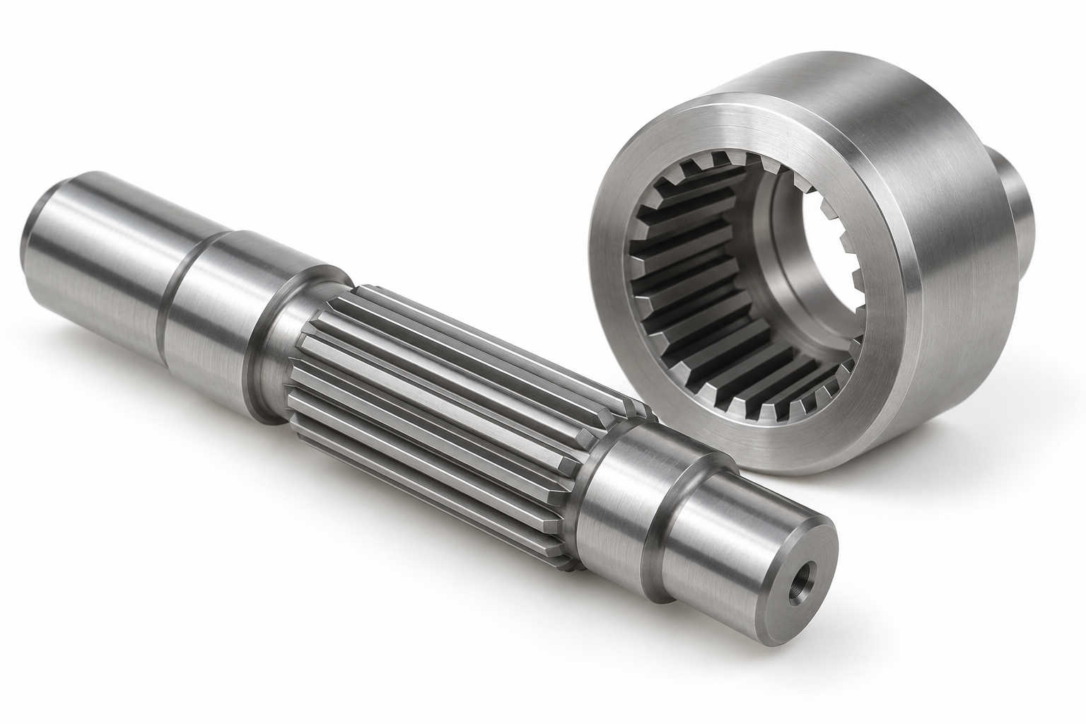
*Illustrative product image of an external spline shaft and mating hub. It is not a photograph of a TOPSHAFT facility or customer part.*
Start With The Functional Requirement
An involute spline specification should begin with the work that the interface must perform. State whether it transmits fixed torque, slides axially, is assembled once, or is repeatedly engaged in service. Those conditions influence fit, tooth condition, lubrication, and inspection planning.
Confirm these functional inputs before choosing a standard designation:
- Required torque direction and load reversals.
- Whether axial sliding is required and the expected stroke.
- Lubrication, contamination, corrosion, and temperature exposure.
- Mating hub material and whether the hub already exists.
- Assembly method, retention method, and serviceability needs.
- Whether interchangeability across production lots or suppliers is required.
The same nominal spline can need a different fit in a sliding coupling than in a fixed gearbox connection. Do not copy a previous drawing callout without checking the mating part and load path. If the shaft drives a gear, motor, pump, or actuator, include the application in the RFQ. It helps the manufacturing review focus on the interfaces that actually govern performance.
Identify The Governing Standard Completely
The drawing should name the spline system and its full designation. “Spline” beside a diameter is not enough. It leaves the supplier to infer tooth form, pressure angle, fit concept, and inspection basis.
For straight cylindrical, side-fitting metric involute splines, ISO 4156-1:2021 provides design and manufacturing information. The ISO 4156 series also addresses inspection of straight, non-helical side-fitting cylindrical involute splines. If your project is based on an inch-series, customer, or legacy system, identify that system instead. Similar-looking splines can be incompatible when their standards differ.
A usable callout normally establishes:
- External or internal spline.
- Tooth count.
- Module or diametral pitch.
- Pressure angle.
- Fit class or tolerance designation.
- Side-fit, major-diameter-fit, or another stated fit concept.
- Root form and applicable relief, where relevant.
- Any approved departure from the named standard.
The standard designation controls the tooth system. It does not replace project-specific instructions. Heat treatment, finish, coating, lead-in condition, concentricity, inspection records, and mating-part restrictions still need clear notes.
Define The Mating Part And The Load Path
A spline is a functional interface, not an isolated shaft detail. The supplier should understand which component mates with it and how the assembly carries load.
Provide a controlled hub drawing, relevant CAD view, or enough interface data to show the mating condition. State whether the hub is available for a trial assembly. If a functional gauge or master hub already exists, identify it in the quotation package. This avoids a situation where shaft teeth are manufactured to an assumed interpretation while the mating component follows another one.
Also show nearby features. The spline may terminate beside a shoulder, snap-ring groove, thread, seal land, bearing journal, or gear seat. These transitions affect cutter access, relief geometry, stress concentration, and inspection setup. A simple section view can prevent an expensive clarification after tooling or machining has begun.
Establish Functional Datums Before Adding Runout
The spline needs to work relative to the shaft axis used in the assembly. Choose datums that represent that real reference.
For many rotating shafts, the functional rotational datum is created by bearing journals or center holes. The axial datum may be a locating shoulder or end face. The correct solution depends on how the component is supported, assembled, and inspected.
Your drawing should make clear:
- The primary rotational datum.
- The axial reference feature.
- Which spline feature is controlled relative to those datums.
- Whether runout applies to a reference diameter, a functional spline measurement, or an assembly check.
- Whether inspection is performed between centers, on journals, or in a dedicated fixture.
Avoid a generic runout callout with no stated feature or datum. A major diameter can appear concentric while the functional tooth relationship is not suitable for the mating hub. Review shaft runout tolerance and inspection and bearing journal specifications when the spline must run with critical journals or gear seats.
Specify Tooth Geometry And Fit Together
Tooth geometry and fit should be controlled as one system. The essential data depends on the governing standard, but the drawing package often needs tooth count, module or pitch, pressure angle, tooth thickness or space width, major and minor diameter limits, and the specified fit class.
For a side-fitting spline, the load is primarily transmitted through the tooth flanks. Major and minor diameters can guide manufacture and inspection, but they do not always prove a functional fit by themselves. The agreed method may use a functional gauge, measurement over pins or balls, span measurement, profile measurement, or another standard-based method.
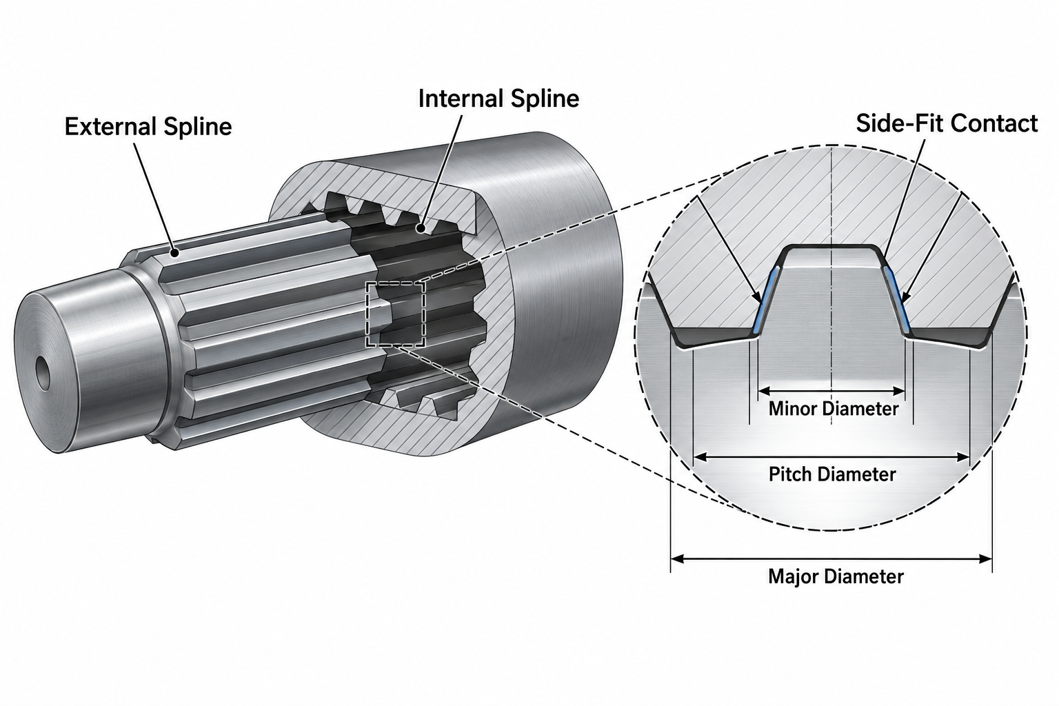
*Illustrative diagram showing the relationship between tooth flanks and reference diameters. The governing drawing standard controls the final values and inspection method.*
When defining the tooth form, also address:
- Effective versus actual measurement requirements.
- Root form, tool relief, and termination condition.
- Chamfers or lead-ins required for assembly.
- Burr limits and edge-break requirements.
- Distance to adjacent shoulders, grooves, or threads.
- Coating restrictions or allowed thickness on functional teeth.
“Remove burrs” can be too vague for a spline. A sharp edge may damage the hub during assembly. Excessive rounding can reduce functional engagement. State the required edge condition around the actual assembly need.
Plan The Manufacturing Route Around The Final Condition
The correct route depends on material, geometry, volume, heat treatment, and final requirements. A typical route can include turning, spline generation, deburring, heat treatment, straightening when appropriate, grinding of critical journals, cleaning, inspection, and protective packing. It is not a fixed sequence for every part.
If teeth are generated before heat treatment, the project must account for dimensional change and potential distortion. If critical journals are ground after heat treatment, the drawing must preserve enough stock and define final dimensions after grinding. If the spline itself needs finishing after treatment, tooling access and process capability need early review.
Material and treatment notes should therefore identify the exact grade or approved-alternative policy, the required condition, treated zones, hardness or case requirements where applicable, and final surface restrictions. The details should be consistent with the shaft heat-treatment specification guide. A material substitution must not be assumed equivalent merely because the nominal strength looks similar.
Agree The Inspection Method Before Production
Inspection should be agreed during quotation, not after the first article has been made. ISO 4156-3 covers inspection requirements and methods for straight, non-helical, side-fitting cylindrical involute splines. The agreed plan may include feature dimensions, measurement over pins or balls, tooth-span measurement, profile evaluation, functional gauges, or a controlled mating-part check.
State what acceptance evidence is required. A practical plan can include the spline standard designation, fit class, inspection method, sample quantity, required report, and any authorized master part or gauge. This helps separate useful inspection from documentation that does not verify the functional feature.

*Illustrative inspection scene. It shows an engineering concept and is not evidence of a TOPSHAFT facility, equipment, or certification.*
The table below helps define an RFQ review.
| Requirement | Why It Matters | Typical Evidence |
|---|---|---|
| Standard and full designation | Establishes the tooth system | Controlled drawing callout |
| Fit class | Defines intended assembly condition | Standard-based gauge or measurement plan |
| Datum relationship | Protects rotation and assembly alignment | Runout or positional inspection report |
| Tooth condition | Avoids assembly damage | Visual and dimensional inspection |
| Material and treatment | Supports strength and wear requirements | Material and process documentation |
| Mating confirmation | Confirms functional assembly | Master hub, functional gauge, or agreed check |
Include The Right Information In Your RFQ
A complete RFQ reduces engineering assumptions and makes quotations more comparable. Send the revision-controlled PDF drawing, native CAD model if available, spline designation, mating-part information, material, heat-treatment requirement, quantity, annual forecast, inspection records, and packing requirement.
If the project is at prototype stage, explain what may change after the first article. If it is repeat production, state the interchangeability and traceability expectations. If a customer-specific gauge is required, confirm who supplies, maintains, and approves it.
For a broader drawing package, use the precision shaft RFQ checklist. The information should support an engineering conversation before the supplier commits to tooling, route, and inspection time.
Avoid These Common Drawing Errors
The most common error is specifying only tooth count and an outside diameter. That does not define the spline system or fit.
Other avoidable issues include mixing metric and inch systems, omitting the fit class, using a non-functional datum, ignoring relief near shoulders, calling for post-coating fit without considering thickness, and requesting reports without identifying an inspection method. These errors can create a part that measures one feature correctly but does not assemble as intended.
Review Cost And Production Risk Early
The spline detail affects more than the machining cycle. It can influence tooling selection, inspection time, material yield, heat-treatment routing, gauge investment, and first-article lead time. The most economical choice is not automatically the loosest fit or the simplest outside diameter. It is the specification that meets the assembly function with a clear, inspectable acceptance method.
For low-volume or prototype work, a supplier may need to use flexible inspection methods while the final mating design is still being validated. For repeat production, a dedicated gauge or validated master part may be practical if it reduces assembly risk and inspection variation. Discuss this trade-off before the purchase order, especially when interchangeability is important.
Avoid requesting a tolerance tighter than the assembly needs merely because a prior component used it. Tightening tooth, concentricity, or finish requirements can add manufacturing and inspection cost without improving functional performance. Conversely, a missing requirement can leave a critical fit uncontrolled. The drawing review should identify both kinds of risk.
When comparing quotations, confirm that each supplier has priced the same standard, fit, material condition, inspection scope, and documentation. A lower price can reflect an omitted gauge, a different interpretation of the spline designation, or a reduced reporting scope. Clear input data makes a commercial comparison more meaningful.
Frequently Asked Questions
Is Tooth Count Enough To Manufacture A Spline Shaft?
No. It does not define module or pitch, pressure angle, fit, tooth thickness, root form, or inspection method.
Should An Involute Spline Use A Functional Gauge?
A functional gauge can be useful when it is aligned with the governing standard and agreed acceptance method. The correct approach depends on the spline system, fit, geometry, and available mating information.
Can A Spline Shaft Be Heat Treated After Tooth Machining?
It can, but the route must account for material response, distortion, finishing allowance, and the required final tooth condition.
What Should Be Sent For A Spline Shaft Quote?
Send the controlled drawing, complete spline designation, mating information, material, quantity, application context, inspection needs, and any required documentation.
Request A Practical Spline Shaft Review
Send your drawing, spline designation, mating data, material, quantity, and inspection requirements through the TOPSHAFT contact page. The review can focus on the complete shaft: spline teeth, journals, shoulders, threads, treatment route, and the features that affect functional assembly.