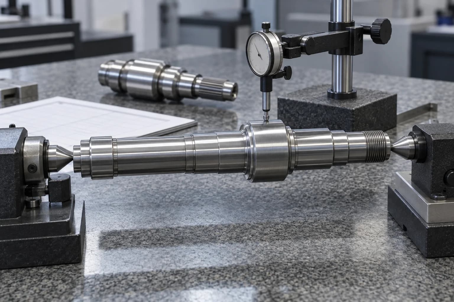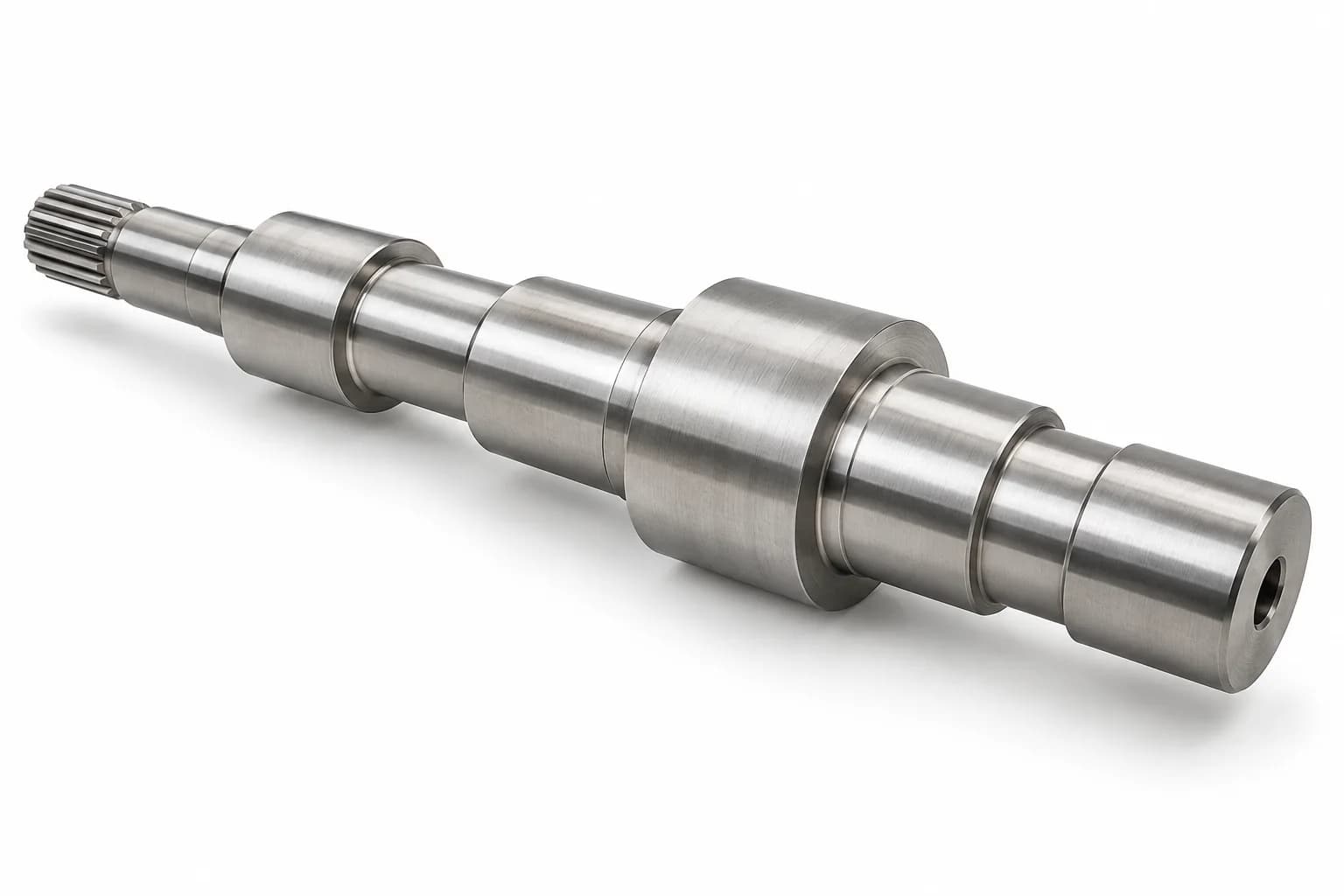
Stepped Inconel Shafts
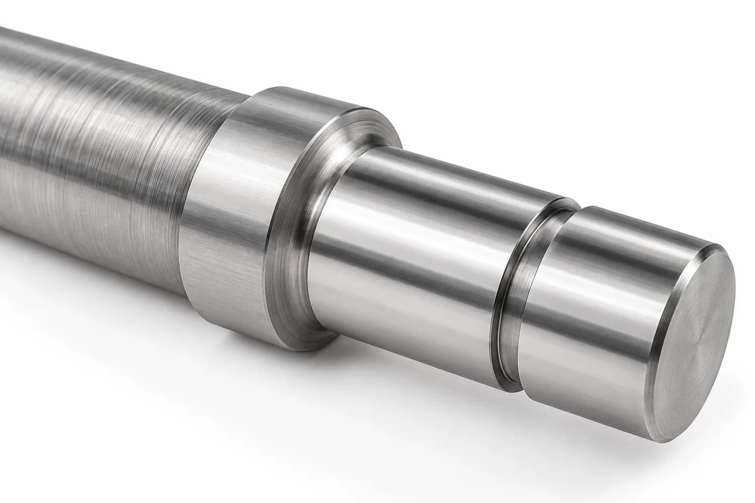
Multiple diameters, shoulders and bearing locations. Define journal spacing, transition radii and functional datums so the machining and inspection route follows the installed load path.
Review shaft geometry
PRECISION NICKEL SUPERALLOY SHAFT MACHINING
Topshaft provides precision CNC machining solutions for custom Inconel shafts used in demanding industrial environments. We support drawing-based shaft projects involving Inconel 625, 718 and 600, with material selection, manufacturing feasibility, critical tolerances and inspection requirements reviewed for each application.
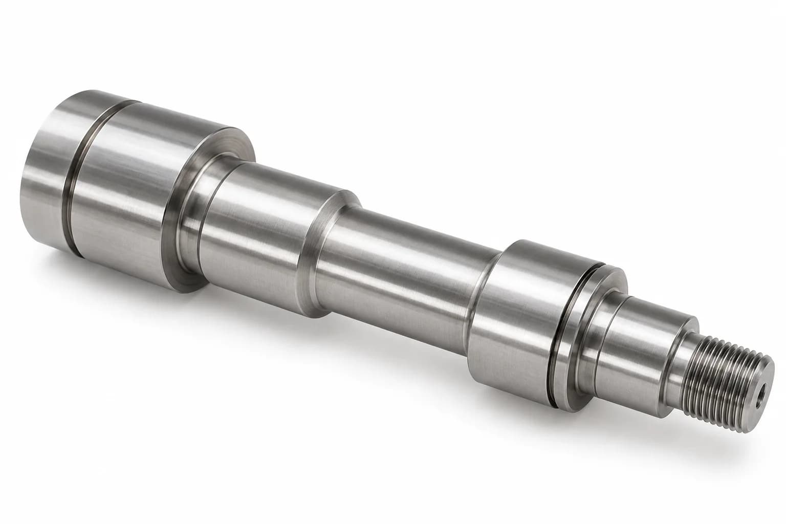
Inconel shafts are precision-machined mechanical components manufactured from nickel-chromium-based superalloys. Depending on the specific grade, they can provide resistance to oxidation, corrosion, elevated temperatures and mechanical stress. They are used in specialized rotating or positioning equipment where conventional shaft materials may not meet the operating requirements.
Alloy choice depends on temperature, mechanical loading, chemical exposure, fatigue requirements and material condition. This page focuses on Inconel-specific shaft machining; the broader Nickel Alloy Shafts page covers the wider material family.
Swipe horizontally to read all columns.
| Attribute | Project information |
|---|---|
| Manufacturing type | Custom / OEM / made to drawing |
| Material grades | Inconel 600, 625, 718 and specified alternatives |
| Processes | CNC turning, milling, drilling and agreed secondary operations |
| Shaft geometries | Straight, stepped, threaded, hollow and custom profiles |
| Critical features | Bearing journals, seal surfaces, shoulders, keyways and grooves |
| Inspection | Drawing-defined dimensional and geometric checks |
| Documentation | Material and inspection records as agreed |
| Production | Prototype evaluation through repeat orders |
Drawing-based geometries for project review, not a catalog of stocked or previously delivered components.
Multiple diameters, shoulders and bearing locations. Define journal spacing, transition radii and functional datums so the machining and inspection route follows the installed load path.
Review shaft geometry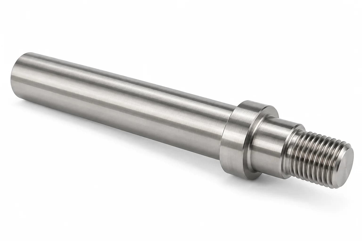
Custom threaded ends and assembly interfaces. Specify thread standard, class, engagement and inspection requirements; a nominal diameter alone does not define the connection.
Review shaft geometry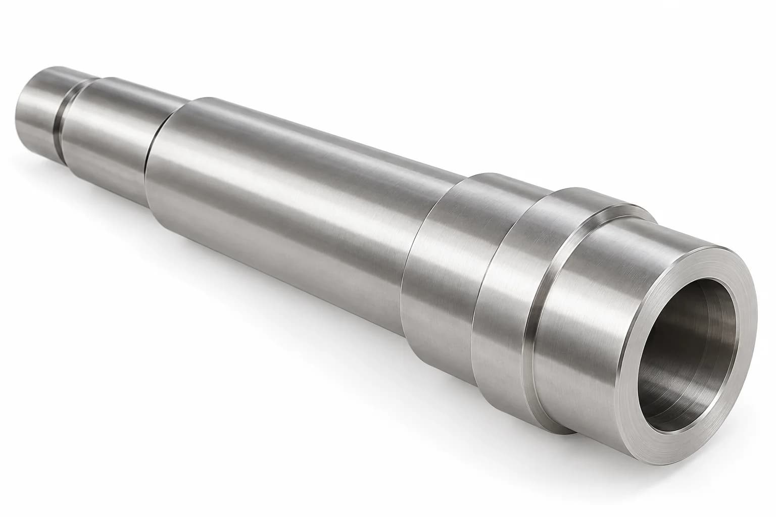
Axial bores and application-specific tubular geometries. Review bore depth, wall thickness, concentric relationships, chip evacuation and access before fixing the manufacturing sequence.
Review shaft geometry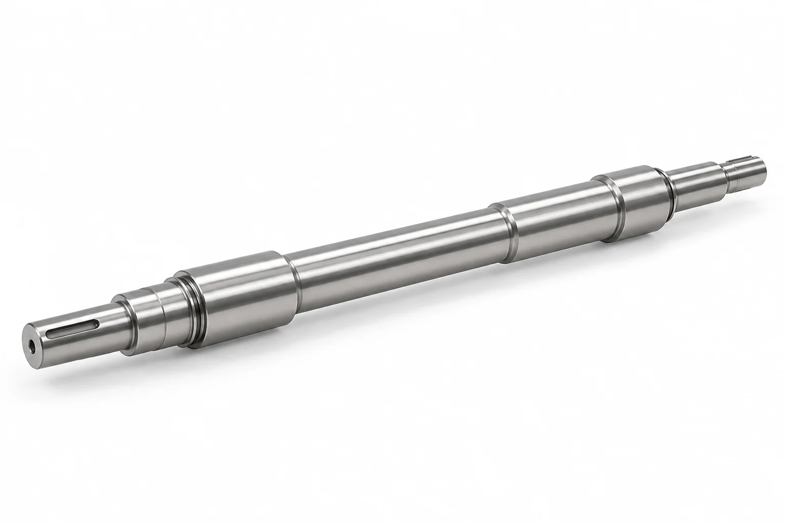
Selected corrosion-resistant fluid-handling applications. Identify the actual fluid, seal lands, bearing seats and coupling interface instead of assuming every nickel alloy suits every pump duty.
Review shaft geometry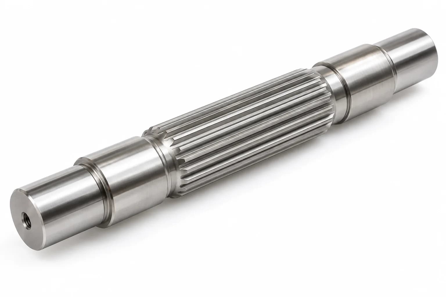
Custom torque-transfer interfaces where appropriate. Supply the spline standard, tooth geometry, fit and functional inspection basis; these features require a dedicated process review.
Review shaft geometry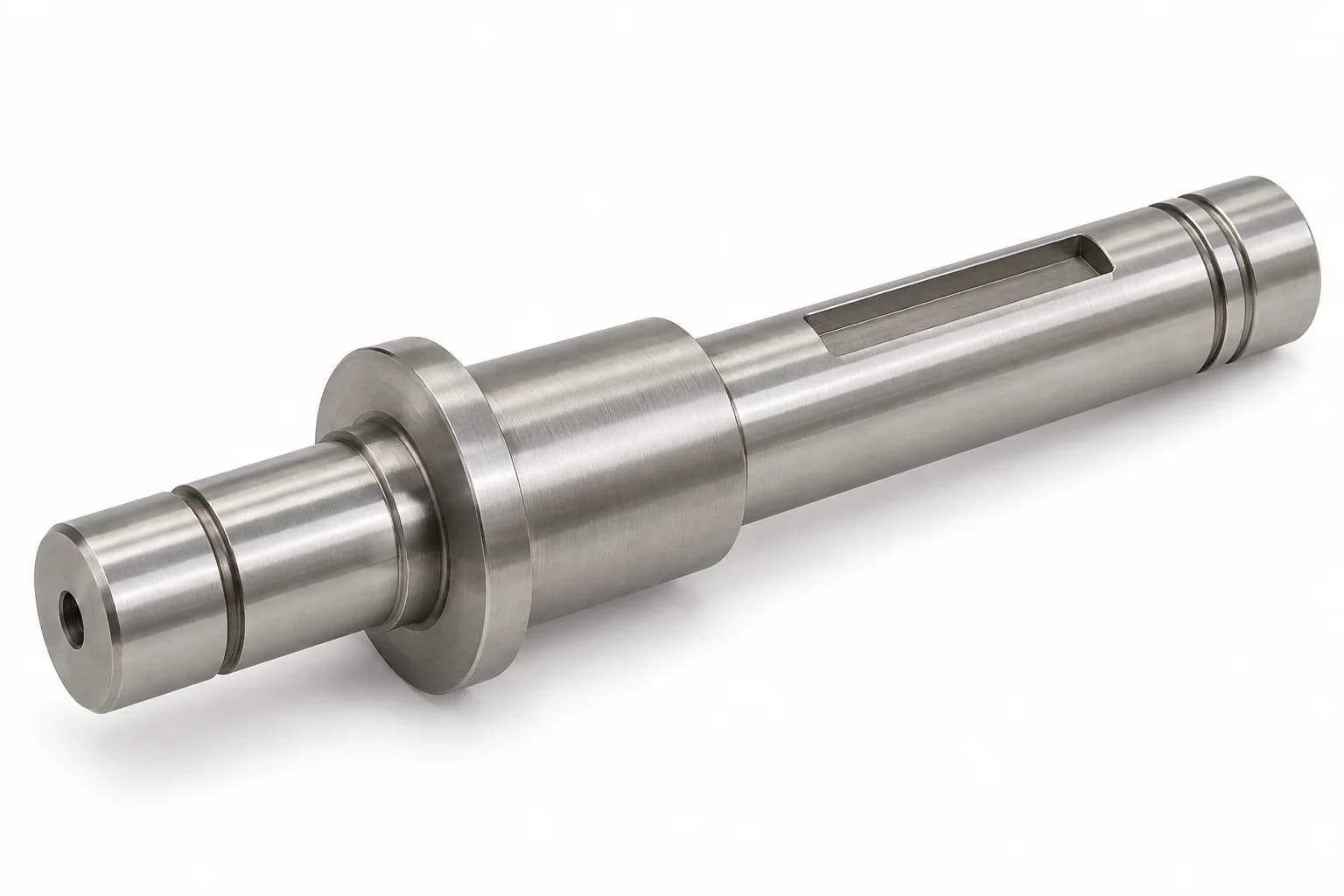
Grooves, flats, keyways and specialized features. Define the features that locate, drive or retain the assembly, including edge condition and relationships to the main shaft axis.
Review shaft geometrySpecify the required aged condition and mechanical-property basis before assessing the process route. High strength alone does not establish fatigue life or a safe service temperature.
Describe the actual medium and exposure. Compare its corrosion behavior and supplied condition with the required strength rather than treating 625 as an interchangeable version of 718.
Swipe horizontally to read all columns.
| Grade | UNS designation | Key characteristics | Potential shaft applications |
|---|---|---|---|
| Inconel 600 | N06600 | Nickel-chromium alloy with useful oxidation and corrosion resistance | Specialized high-temperature equipment |
| Inconel 601 | N06601 | Strong oxidation resistance at elevated temperatures | Furnace and thermal-processing components |
| Inconel 625 | N06625 | Strong corrosion resistance and useful mechanical strength | Chemical processing and marine equipment |
| Inconel 718 | N07718 | Precipitation-hardenable alloy with high strength and good elevated-temperature properties | High-load, high-temperature precision shafts |
| Inconel X-750 | N07750 | Precipitation-hardenable nickel-chromium alloy | Specialized high-temperature mechanical components |
Inconel 600 is another principal review option; 601 and X-750 are additional material-selection possibilities. These are not inventory guarantees. Grade-specific corrosion resistance, temperature capability and machining behavior differ; material sourcing must be confirmed during quotation.
Swipe horizontally to read all columns.
| Factor | Inconel 718 | Inconel 625 | Inconel 600 |
|---|---|---|---|
| Main advantage | High strength after appropriate aging treatment | Corrosion resistance | Oxidation and corrosion resistance |
| Strengthening mechanism | Precipitation hardening | Primarily solid-solution strengthening | Primarily solid-solution strengthening |
| Machining difficulty | High | High | High |
| Typical selection driver | Mechanical loading and elevated temperature | Aggressive environments | Selected thermal and chemical environments |
| Key design consideration | Heat-treatment condition | Actual corrosive medium | Actual service temperature and environment |
Inconel 718 is often considered when high strength is a major requirement, while Inconel 625 may be preferred for certain corrosion-intensive environments. Inconel 600 is considered for specific oxidation and corrosion conditions. Final selection requires application-level engineering review.
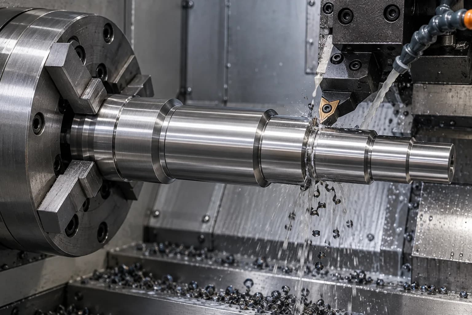
External diameters, bearing seats, shoulders, grooves and threaded features are planned around the specified alloy condition. Roughing and finishing allowances must accommodate tool wear, work hardening and later treatment. Long parts need reviewed support rather than an unsupported cutting setup.
Related capability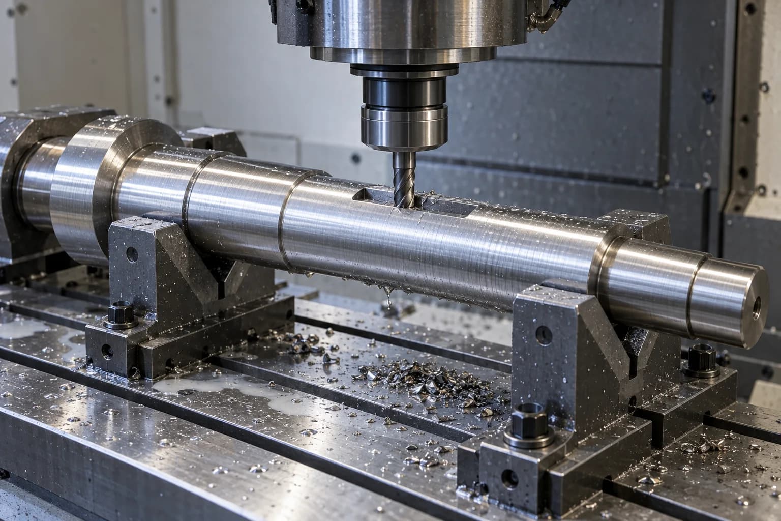
Flats, slots, keyways and complex non-rotational features require stable fixturing and suitable cutter engagement. Re-clamping should preserve the relationship to turned datums. Access, interrupted cutting and chip removal matter particularly around shoulders and narrow slots.
Related capability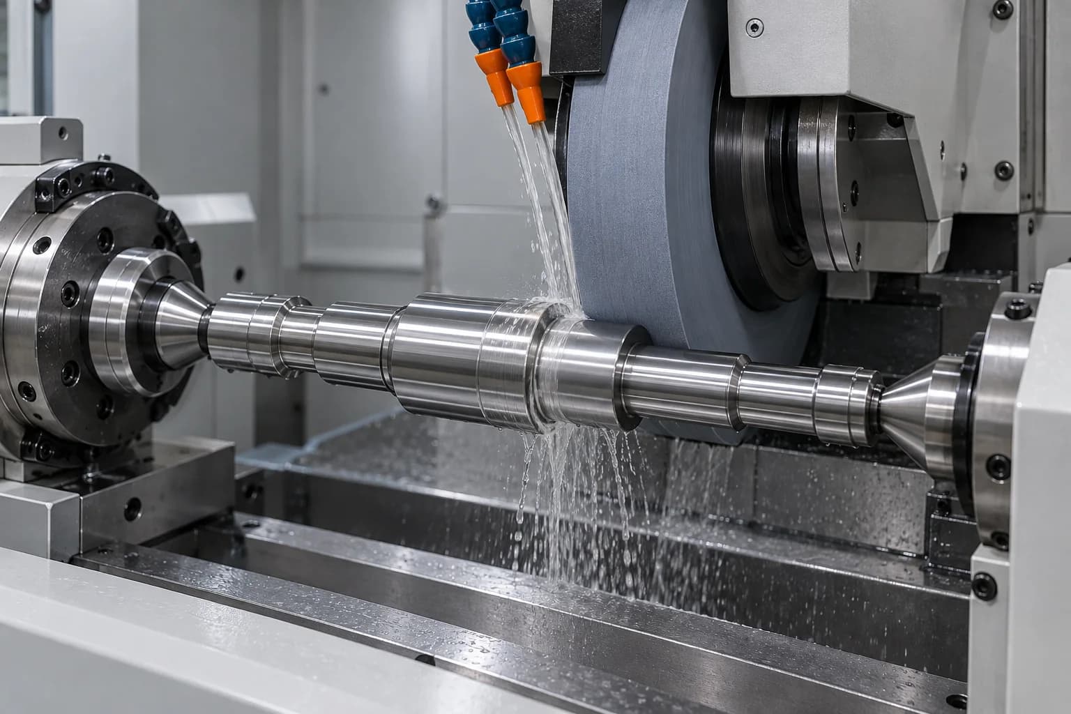
Final functional diameters and surface finishing may use cylindrical grinding where feasible. Wheel selection, dressing, cooling and stock removal must suit the alloy and final condition. Grinding is reviewed for each geometry, not promised for every bore or inaccessible feature.
Related capability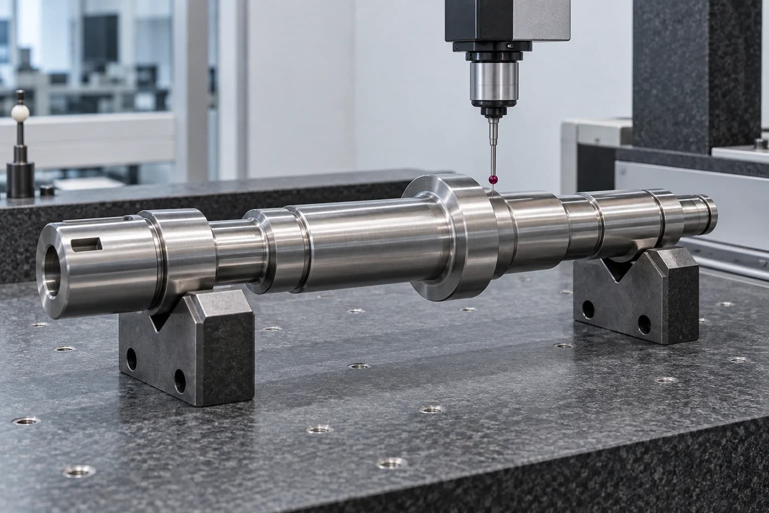
Critical diameters, runout, straightness and drawing-defined geometry are checked at planned stages. Measurement after the final relevant treatment and finishing operations provides the agreed acceptance basis. Inspection methods and records should be established before manufacture rather than added at shipment.
Related capabilityThe route connects material verification, workholding, rough machining, agreed treatment, final features and inspection. See Custom Shaft Manufacturing for the general service; the Inconel route must be adapted to the specified nickel superalloy.
Swipe horizontally to read all columns.
| Challenge | Technical explanation | Recommended manufacturing response |
|---|---|---|
| Work hardening | Cutting can harden the surface ahead of subsequent passes | Appropriate feeds, cutting depth and tool engagement |
| High cutting temperature | Heat can concentrate near the cutting zone | Suitable tooling and controlled cooling |
| Accelerated tool wear | High cutting forces and temperature increase tool wear | Tool-life monitoring and appropriate cutting materials |
| Chip control | Tough, ductile chips can complicate machining | Suitable insert geometry and chip-breaking strategy |
| Long-shaft deflection | Slender geometry is sensitive to cutting forces | Tailstock, steady-rest or suitable workholding review |
| Dimensional stability | Multiple operations and material condition can affect final geometry | Process sequencing, finishing allowance and inspection |
Avoid rubbing, uncontrolled re-cutting of hardened surfaces and treating worn tooling as a harmless productivity issue. Tool engagement, cooling and support must be considered together. No universal cutting speed or feed is specified here: grade, material condition, tooling, operation and machine setup determine a responsible cutting strategy.
There is no universal ±0.005 mm tolerance for all Inconel shafts. Achievable precision depends on material condition, geometry, process route and final inspection requirements.
Swipe horizontally to read all columns.
| Specification | Drawing-based requirement |
|---|---|
| Material grades | 600, 625, 718 and drawing-specified grades |
| Material standards | Applicable ASTM, AMS or customer specifications |
| Shaft diameter | Confirmed against drawing and machine capacity |
| Shaft length | Subject to geometry, workholding and material review |
| Dimensional tolerances | Confirmed during engineering feasibility assessment |
| Geometric tolerances | Runout, straightness, roundness and coaxiality |
| Surface roughness | Defined according to bearing, seal and assembly requirements |
| Heat treatment | Grade- and condition-specific |
| Material certification | Agreed during quotation and order review |
| Production quantity | Prototype, low-volume and repeat production |
Heat treatment can change dimensions. Plan the final bearing journals, seal surfaces and other critical features after reviewing the required treatment sequence. Conventional carbon-steel hardening procedures do not apply to every Inconel grade.
State continuous, peak and reversing torque. Check the remaining section at splines, keyways, grooves and threads, not only the largest outside diameter.
Define bearing spans, overhangs and radial loads. Higher material strength does not automatically solve deflection or alignment problems in a flexible geometry.
Include load cycles, start-stop duty and vibration. Surface condition, notches, residual effects and transitions influence the fatigue assessment of a rotating shaft.
Provide continuous and transient temperatures, exposure time and gradients. Room-temperature strength and a general alloy temperature range are not shaft design allowables.
Identify chemicals, concentration, contamination, pressure and cleaning media. Compare the exact grade against the real exposure rather than a generic corrosion-resistance ranking.
Review unsupported length, cutting forces, workholding and running behavior. Support locations and machining access should be assessed before committing to final geometry.
Define fit, journal finish and acceptance temperature. Thermal expansion of the shaft, bearing and housing must be considered as an assembly relationship.
Use feasible fillets and reliefs around diameter changes. Coordinate keyway ends, thread runouts and shoulders with both the load path and tool access.
Name the datum system, GD&T standard and critical features. Ensure the chosen measurement setup can verify the functional relationships shown on the drawing.
Swipe horizontally to read all columns.
| Industry | Potential application | Engineering priority |
|---|---|---|
| Chemical processing | Pump shafts and specialized equipment | Chemical compatibility |
| Oil and gas | Selected rotating mechanical components | Corrosion, temperature and load |
| Energy equipment | High-temperature rotating components | Strength and thermal exposure |
| Marine equipment | Specialized pump and machinery shafts | Corrosion and material compatibility |
| Aerospace | Specialized mechanical shafts | Material condition, traceability and qualification |
| Industrial machinery | High-temperature or corrosion-resistant shafts | Dimensional stability and operating duty |
These are application directions, not claims of delivered projects or aerospace, nuclear or oil-and-gas qualification. Customer approvals, manufacturing controls and supporting evidence must be agreed where the application requires them.
Swipe horizontally to read all columns.
| Factor | Inconel | Stainless steel | Titanium |
|---|---|---|---|
| Density | High | High | Relatively low |
| Corrosion resistance | Excellent in selected environments | Grade-dependent | Excellent in many environments |
| High-temperature capability | Strong in selected grades | Grade-dependent | Application- and grade-dependent |
| Machining difficulty | Generally high | Varies | Generally high |
| Material cost | Usually high | Often lower | Usually high |
| Main selection driver | Severe thermal, corrosion or mechanical requirements | General corrosion-resistant engineering | Weight reduction and corrosion resistance |
These are qualitative selection directions, not guaranteed properties of every grade. Weight, corrosion mechanism, thermal exposure, material condition and machining cost must be assessed for the actual assembly.
Check specified sizes at defined locations, after the operations that determine the final condition. Agree the reporting scope for critical fits.
Measure relative to the drawing's datum axis and specified support arrangement; an unexplained indicator reading is not a complete acceptance criterion.
Distinguish axis straightness from local surface form and runout. Shaft length, supports and measurement method belong in the inspection plan.
Review bearing and seal surfaces against the required parameter and measurement direction. Visual polish cannot replace a stated roughness requirement.
Verify the specified thread standard, size and fit using the agreed method. Include runout and shoulder relationships where the drawing makes them functional.
Confirm axial positions, perpendicularity, roundness and coaxial relationships as specified, recording agreed critical characteristics rather than inventing universal limits.
Specify alloy grade, UNS designation, material condition, heat/lot identification and required documentation at quotation. The identity must remain linked to the finished components through machining and any agreed treatment. Material Traceability explains heat-number and certificate control; document type and availability remain order-specific.
Critical geometry, bearing interfaces, datums and manufacturing feasibility are reviewed together. Inconel shaft projects are assessed against the actual alloy, condition and drawing.
Turning, milling, agreed secondary operations, finishing and inspection are sequenced as one route. Treatment responsibilities and finishing allowances need agreement before production.
Critical dimensions and geometric requirements are defined before manufacturing. Specify acceptance criteria and required records so the quotation includes the intended inspection scope.
Manufacturing routes and inspection plans are established around the approved project. Prototype findings and drawing revisions should be resolved before repeat orders are released.
TOPSHAFT is the precision shaft manufacturing division of Dongguan Tops Precision Manufacture Co., Ltd., operating alongside Topsbest Precision for shaft-focused OEM projects. Review company information. Actual Inconel machining experience, sourcing and treatment support must be confirmed for the proposed project; no extensive production history is implied.
An Inconel shaft may be selected for specialized rotating or positioning equipment exposed to temperature, corrosion or mechanical loading that makes conventional materials unsuitable. Potential uses include selected pump, energy and industrial machinery components. The grade and duty must be evaluated together; naming an industry does not establish qualification or completed production experience.
The central distinction is the material-selection driver and strengthening route. Inconel 718 is precipitation-hardenable and is often reviewed for high strength in an appropriate aged condition. Inconel 625 is primarily solid-solution strengthened and is often considered for demanding corrosion environments. Neither is universally superior; exposure, loading, condition and the applicable specification govern selection.
Generally, yes. Work hardening, concentrated cutting heat, high forces and tool wear complicate shaft machining. Rigid support, appropriate tooling, controlled cooling, chip management and a planned finishing sequence help manage these effects. Cutting parameters cannot be quoted responsibly without the grade, condition, operation and setup.
Drawing-defined precision can be evaluated, but no universal tolerance applies to every Inconel shaft. Diameter, length, wall thickness, material condition, heat treatment, available finishing methods and inspection access all affect feasibility. Submit the actual drawing so critical dimensions, geometric tolerances and acceptance methods can be reviewed before order confirmation.
It can be considered for selected high-strength, elevated-temperature shaft duties in a specified material condition. Suitability still depends on stress, fatigue, creep, temperature exposure, environment and required life. A generic alloy temperature range is not a safe operating limit for a loaded rotating component; application-level engineering review is essential.
Inconel may offer advantages in selected severe thermal or corrosion conditions, but it normally brings higher material and machining costs. A suitable stainless grade can be economical and technically sufficient for many industrial duties. Compare actual failure mechanisms, material condition, component geometry and lifecycle requirements rather than choosing on the alloy name alone.
Topshaft reviews drawing-based Inconel shaft projects for manufacturing feasibility. Provide the alloy designation, supplied and final condition, geometry, quantity and critical requirements. Material sourcing, machining route, treatment responsibilities and documentation must be confirmed for the proposed project; this is not a claim that every grade or geometry is routinely available.
Send a controlled 2D drawing or 3D CAD model, alloy grade and UNS designation, material condition, shaft dimensions, quantity, critical tolerances, heat-treatment requirements, operating environment, inspection documents and target delivery date. Include drawing revision and any customer approval or traceability requirements, so quotation and order review use the same acceptance basis.
Send your 2D drawing or 3D CAD model, alloy grade, material condition, shaft dimensions, quantity, critical tolerances, heat-treatment requirements, operating environment, inspection documents and target delivery date. Identify requirements that are mandatory for approval so they can be included in feasibility and quotation review.