
Shaft Straightness: How to Specify, Measure, and Control It
A shaft can have the right diameter, surface finish, and hardness yet still create an assembly problem if it is not straight enough for its function. Straightness influences bearing loading, seal life, carriage travel, coupling alignment, and the stability of rotating or sliding equipment. It is especially important on long, slender parts where a small deviation can become meaningful at the working length.
For a buyer or design engineer, the useful question is not simply, “What straightness can you hold?” The better question is: which feature must be straight, over what length, relative to which functional reference, and how will the result be measured? A drawing that answers those questions gives the manufacturer a real basis for planning the machining route and inspection method.
This guide explains how to make shaft straightness requirements practical, measurable, and connected to the application.
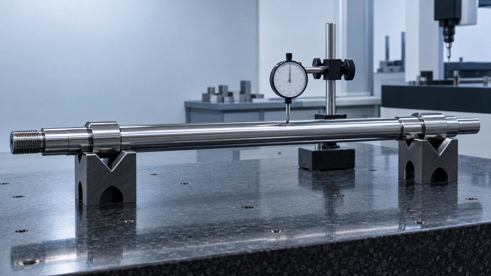
*Illustrative technical image: a shaft supported on V-blocks while an indicator checks deviation along the length. It is not a photograph of a TOPSHAFT facility.*
What shaft straightness controls in an assembly
Straightness is the condition of an individual line element or derived axis. On a shaft, the requirement commonly concerns the centreline of a cylindrical journal or the surface line along a specified region. The functional consequence depends on what that region does.
For a bearing journal, poor straightness can contribute to uneven contact and unwanted load distribution. For a shaft that passes through seals, it can make the running condition less consistent. On a guide or linear motion shaft, it can affect carriage movement over the usable stroke. On a motor or drive assembly, the relationship between journals, coupling seats, and mounted components determines whether the part will assemble and rotate as intended.
That is why a general note such as “keep straight” is not enough. A long, non-critical extension may tolerate more deviation than a bearing seat. A shaft that is supported at several points may behave differently from one that is cantilevered. The drawing should identify the working zones rather than applying an unnecessarily tight condition to every surface.
Straightness, runout, and roundness are different controls
These terms are often used interchangeably in an RFQ, but they answer different questions.
- Straightness asks whether a line or axis remains within a permitted straight zone. It can be applied to a surface element or to a derived axis.
- Runout is observed while the part is rotated about a selected datum axis. It combines the effects of feature location, form, and setup relative to that reference. Our shaft runout tolerance guide explains why the datum and the inspection setup matter.
- Roundness considers how close a circular cross-section is to a perfect circle. A round journal is not automatically straight over its full length.
A shaft can show low runout at one inspection location and still have an unacceptable bend elsewhere, particularly if the inspection supports or datum axis do not represent the function. Conversely, an indicator reading taken on a slightly out-of-round surface can look like a straightness issue when it is actually a form issue. Defining the requirement and the measurement method together prevents the supplier and buyer from evaluating different conditions.
Start with the feature and the functional length
The first decision is the feature being controlled. A requirement may apply to the entire shaft axis, to one long journal, or to a specific sliding or sealing land. The functional length should be shown on the drawing. When a stepped shaft contains threads, splines, shoulders, and journals, it is rarely useful to treat every area as one continuous inspection target.
For example, consider a shaft with two bearing journals separated by a gear seat. The design may need the journals to support the assembly on a stable axis, while the gear seat needs a relationship to that axis. In that case, the drawing should establish the datum strategy and identify the critical zones. The same thinking applies to a bearing journal: the journal diameter, surface condition, and axis relationship should be reviewed as a functional set.
It also helps to state whether the condition is required before or after a later process. Heat treatment, coating, straightening, and final grinding can each affect the final condition. If the requirement is for the finished delivered part, it should be evaluated in the finished state unless the drawing clearly says otherwise.
Why long shafts need a realistic specification
Straightness becomes more sensitive as length increases. A short journal can be held in a rigid setup with little influence from its own weight. A longer, smaller-diameter part is more likely to deflect under gravity, residual stress, clamping, cutting forces, or thermal change. Material condition and process sequence matter as much as the numerical tolerance.
Common influences include:
- Length-to-diameter ratio. Long, slender shafts are more responsive to support spacing and handling.
- Material and incoming condition. Residual stress in bar stock can be released during rough machining.
- Machining sequence. Removing material unevenly can change the part’s condition between operations.
- Heat treatment. Quench-and-temper, induction hardening, carburizing, nitriding, and stress relieving can introduce or relieve distortion depending on the material and route.
- Clamping and transport. A compliant shaft can be changed by excessive clamping force or unsupported handling.
- Final process. Turning, grinding, centreless grinding, straightening, and polishing do not control the same conditions in the same way.
For this reason, an unusually tight value should be tied to a real assembly need. Tightening a drawing tolerance without defining the functional reason can increase process complexity, inspection time, scrap risk, and cost without improving the product.
Choose a measurement method before quoting
A measurement result is meaningful only when the support, datum, probing path, and acceptance rule are understood. A supplier can use different methods depending on the part geometry and requirement.
V-blocks and a dial indicator
For a cylindrical section, the shaft can be supported on controlled V-blocks or rollers and checked with an indicator as the probe travels along the relevant length. The support locations must be suitable for the part and should avoid contacting threads, delicate surfaces, or areas that distort the result. If the shaft is rotated during the check, the team must also separate any roundness effect from the axial straightness result.
Between centres
Centres can be a useful reference when centre holes or functional centre locations are available. This setup is often relevant for long shafts because it can relate the check to a centre-based manufacturing reference. It still needs a defined procedure: the support condition, rotational state, and probed sections affect the reading.

*Illustrative technical image: inspection equipment arranged around a shaft between centres. It is not a photograph of a TOPSHAFT facility.*
CMM, optical, or dedicated inspection equipment
Coordinate measurement, optical systems, or dedicated gauges can be appropriate for complex parts, critical axis relationships, and documented inspection plans. They are particularly useful where the drawing combines straightness with datum-based location controls. The chosen method should be capable of supporting the required uncertainty and part size; the most advanced instrument is not automatically the best method for every long shaft.
In an RFQ, it is reasonable to ask the manufacturer to confirm the proposed inspection arrangement. TOPSHAFT’s inspection and quality capability is built around drawing-defined dimensions and records, so the required deliverable should be discussed with the drawing instead of assumed from a generic statement.
Specify the datum strategy when relationships matter
Straightness of a surface line can be controlled without a datum. But an assembly frequently needs more than an isolated line condition. It may need bearing journals, a coupling seat, and a gear location to relate to one functional axis. That is where datum selection becomes essential.
Choose a datum from a feature that represents how the part locates or rotates in the real assembly. It might be a primary journal, paired journals, centre holes, or another designed reference. Then place the remaining controls in relation to that axis where appropriate. Avoid using a cosmetic or difficult-to-measure feature as a datum merely because it is convenient on the drawing.
This distinction also helps avoid an over-specified drawing. If the objective is low indicator runout of a gear seat relative to bearing journals, a datum-based runout or location control may be more direct than adding tight straightness to every feature. If the objective is smooth travel along a long guide surface, a local or full-length straightness requirement may be the relevant control.
Build process control around the final requirement
Manufacturers do not usually “inspect quality into” a shaft at the end. The machining route should leave a practical path to the final condition. A typical approach may include stable stock selection, rough machining, stress-relief or heat-treatment stages where required, semi-finish machining, controlled straightening if appropriate, and final turning or grinding of critical surfaces.
The sequence depends on the material, geometry, heat treatment, and requested properties. A hardened motor shaft, for example, may need a different route from a low-carbon welded or fabricated shaft. A drawing with clear material and treatment information allows the team to decide whether critical dimensions should be finished before or after treatment and whether additional stock must be retained for grinding.

*Illustrative technical image: cylindrical grinding of a long shaft. It represents a possible finishing process, not a claim about a specific customer part or TOPSHAFT production route.*
Final finishing can improve a critical surface, but it is not a universal correction for every straightness problem. If residual stress, a major bend, or an unsuitable geometry is present, the production team may need a different controlled action. This is why the earlier design and manufacturing review matters.
What to include in a straightness-related RFQ
When requesting a quote, send the current drawing and include the information that changes the route or inspection plan. A complete RFQ should normally cover:
- The material grade and any required material condition.
- Overall length, diameters, and the specific feature or span that is critical.
- The straightness requirement, including whether it applies before or after treatment, coating, or finishing.
- Datum references and related runout, concentricity, or position requirements where the assembly needs them.
- Heat treatment, hardness, plating, coating, or corrosion-protection requirements.
- Surface-finish expectations for journals, seals, or sliding regions.
- Quantity, prototype or repeat-production status, and the required inspection documentation.
If a previous part failed in service, explain the observed condition rather than only tightening a number. Was the issue bearing temperature, seal wear, vibration, carriage binding, or assembly alignment? That detail helps distinguish between straightness, runout, surface finish, or another cause. The precision shaft RFQ checklist offers a useful starting point for organizing this information.
Practical questions to ask before release
Before releasing a drawing, ask the following:
- Which surface or derived axis is actually responsible for the functional requirement?
- Is the tolerance applied over the correct working length?
- Does the drawing distinguish straightness from runout and roundness?
- Are the datums based on how the part locates in the assembly?
- Does the specified state account for heat treatment, coating, and final grinding?
- Can the inspection method reproduce the condition without ambiguity?
- Have prototype quantity, documentation, and acceptance requirements been stated?
These checks make the requirement more likely to be understood consistently by design, purchasing, manufacturing, and quality teams.
FAQ
Does low runout guarantee that a shaft is straight?
No. Runout is evaluated relative to a reference axis while the part rotates. It can be influenced by roundness, feature location, and the setup. A shaft can meet a runout requirement at selected positions yet still require a separate straightness evaluation over a longer functional span.
Can a shaft be straightened after heat treatment?
Sometimes, but the answer depends on the material, treatment, geometry, hardness, and required final properties. The process should be reviewed before quoting rather than assumed after a part has been made.
Should straightness be specified across threads, splines, and journals as one length?
Only when that represents the functional need and the inspection plan can support it clearly. In many cases, it is better to identify the critical journal, guide, or sealing spans and define their relationship to the functional datum axis.
Turn the requirement into a manufacturable plan
Straightness is not a generic “precision” label. It is a functional condition that must be connected to the working feature, length, datum strategy, process route, and inspection method. Clear requirements help the manufacturer quote responsibly and help the buyer compare proposals on the same technical basis.
If you are preparing a long or critical shaft, send TOPSHAFT your drawing and requirements. Include the functional areas, treatment condition, quantity, and any inspection record you need. The engineering review can then focus on a practical route from prototype through repeat production.