
Shaft Balancing Requirements: What OEM Buyers Should Specify Before Production
Your balancing requirement needs more than a grade on a drawing. Define the rotor, operating conditions, acceptance limits and permitted corrections together. You also need a report that identifies the tested configuration. This guide helps you turn those decisions into a practical supplier requirement.
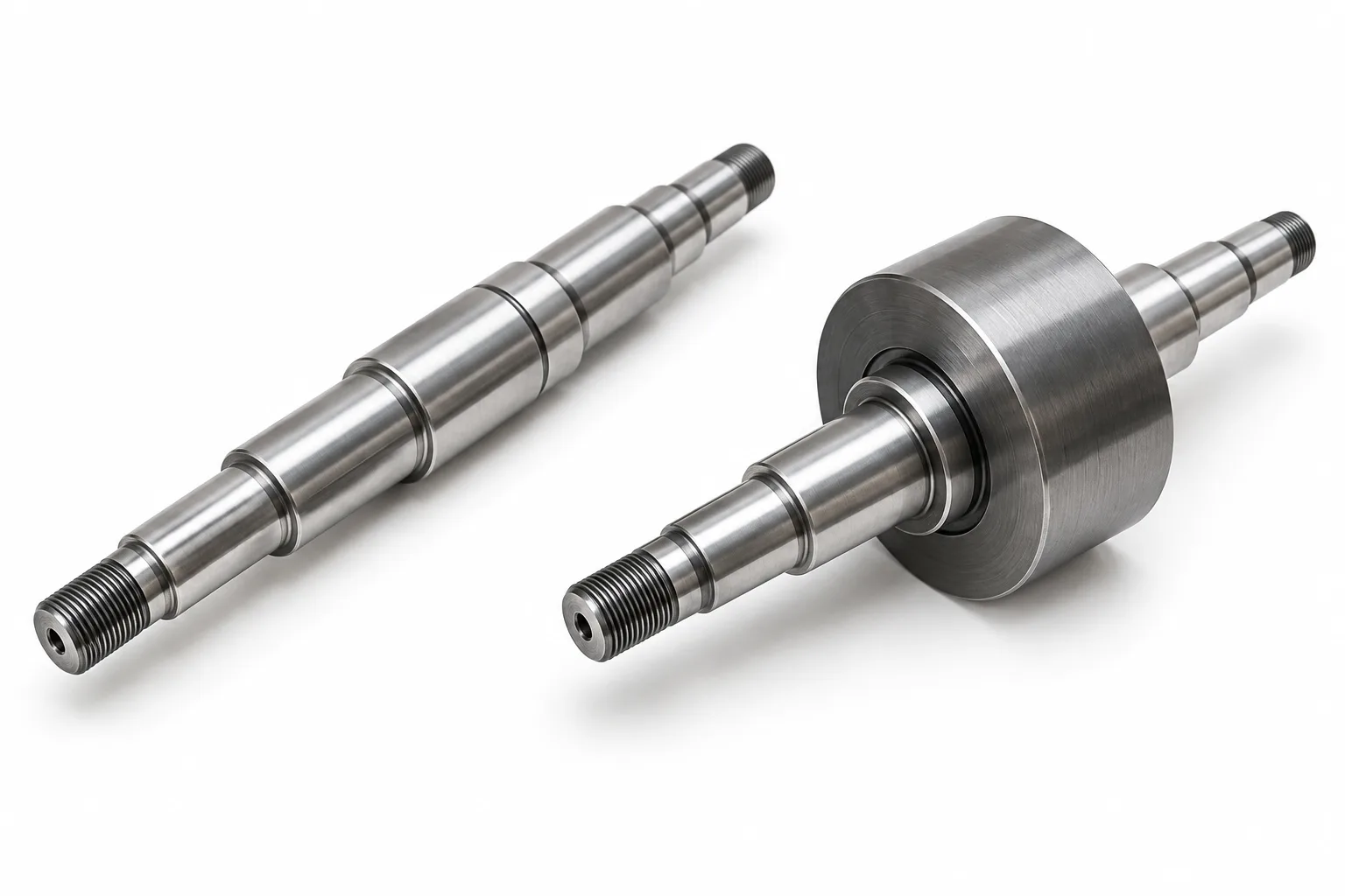
AI-generated illustration of generic rotor configurations, not an actual TOPSHAFT customer component.
Define The Rotor Being Balanced
A balancing requirement applies to a defined rotor configuration, not simply to a product name.
You might purchase a bare shaft, a shaft with a hub, or a complete rotating assembly. Those configurations differ. Added components and their mounting conditions can change the mass distribution around the rotation axis.
Start by identifying the delivered part number and drawing revision. Then list the components included during balancing. State whether the supplier balances the delivered assembly or a temporary manufacturing configuration.
For a motor project, clarify whether the rotor stack is included. For a drive assembly, identify coupling hubs and mounted hardware. For a pump, identify the impeller configuration and its assembly position.
Do not assume a balanced bare shaft proves that your final assembly meets its balancing requirement. Equally, do not request assembly balancing from a supplier delivering only the bare shaft without discussing responsibilities.
Your purchasing specification should connect the balancing operation with the delivered condition. Identify who installs remaining components and who verifies the completed rotor.
For shaft manufacturing details, review the relevant motor shaft requirements before separating component and assembly responsibilities.
Separate Balance From Runout
Balancing assesses mass distribution, while runout assesses geometric variation relative to a specified rotation reference.
These requirements address different problems. A dimensionally acceptable shaft can still have an unacceptable mass distribution. A balanced rotor can still have unacceptable journal runout, alignment or fit.
Keep both requirements on the drawing when your application needs them. Specify journal diameters, geometric controls and surface condition independently. Do not replace those controls with a balancing note.
Identify the features used to support the rotor during each inspection. A runout measurement between centers differs from one referenced to bearing journals. The reported result depends on that setup.
You should also separate rotor balancing from diagnosing every source of machine vibration. Bearing condition, alignment, looseness and operating behavior require their own assessment. A balance report does not certify the entire machine.
Ask for separate evidence when both geometry and balance matter. Your inspection and quality requirements should state the measurement references and acceptance limits clearly.
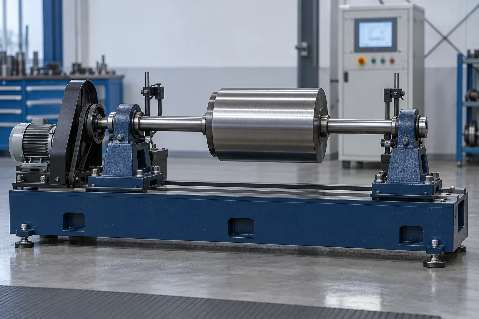
AI-generated illustration of a generic balancing setup, not evidence of TOPSHAFT equipment or an actual test.
Specify Speed And Acceptance Criteria
A usable balancing specification connects the acceptance criterion with the rotor and its relevant operating conditions.
Provide the normal operating speed and the intended speed range. Identify relevant overspeed conditions separately where your design requires them. Do not treat overspeed testing and balancing as interchangeable operations.
Name the applicable standard and edition. Identify the selected quality grade or residual-unbalance criterion, where applicable. Your engineering team should select that requirement from the rotor design and application.
ISO 21940-11 addresses balancing procedures and tolerances for rotors with rigid behavior. Its scope includes residual unbalance, correction planes, tolerance allocation and balancing errors.
The standard does not cover rotors with flexible behavior. That distinction matters before you select a balancing procedure. Do not classify a rotor solely from its length, appearance or product category.
Avoid copying a familiar grade from another drawing without checking its applicability. A grade alone leaves important inputs unresolved. Confirm the rotor mass, relevant speed and method used to establish permitted residual unbalance.
If your drawing gives numerical limits, include units and allocation between the relevant tolerance planes. Distinguish overall limits from plane-specific limits. Resolve conflicts between the drawing, purchase order and supplier procedure before production.
You also need agreement on the balancing test speed. It need not be identical to operating speed in every procedure. The applicable method and rotor behavior determine what is appropriate.
Require your supplier to identify any unresolved assumptions during quotation. That is safer than discovering different interpretations after the parts arrive.
Define The Assembly Condition
The specified assembly condition makes your balance result repeatable and relevant to the delivered rotor.
List installed hubs, sleeves, spacers, fasteners and other rotating components. Specify their axial locations and orientation when those details affect the test configuration.
For keyed interfaces, define the agreed key convention. State whether a key, compensation arrangement or another specified condition is used. Your engineer should approve the convention rather than leaving it implicit.
Identify any hardware temporarily fitted for testing. Explain whether that hardware is removed before shipment. Include its identification in the report when it affects the interpretation of results.
Where components must remain matched, require appropriate identification and assembly instructions. A buyer receiving loose parts needs to know which items belong together. Avoid relying on undocumented shop knowledge.
Consider what happens after balancing. Disassembly, replacement components or a changed mounting position may alter the configuration. Agree when reassembly requires another balance verification.
Your coupling shaft-end specification should align with the balancing configuration. Fits, axial position and key arrangements should not contradict each other.
Identify Permitted Correction Areas
Balance corrections must stay within engineering-approved areas and preserve the shaft’s functional requirements.
Specify where material removal or an approved added mass is permitted. Also identify prohibited areas. Bearing journals, sealing surfaces, threads and critical interfaces should not become convenient correction sites without approval.
Do not let a general balancing note override dimensional tolerances. A correction that damages a seal seat or weakens a critical section creates another problem. The final part still needs to meet its drawing.
Define relevant restrictions on drilling, grinding or other correction methods. Include limits on depth, location and finishing where your design requires them. Added masses need an approved retention method suitable for the application.
Ask your designer to review correction zones for structural and fatigue implications. This article cannot determine safe correction dimensions for your specific rotor. That decision requires the actual design and operating loads.
Require approval when the available correction area is insufficient. Your supplier should not improvise a new correction location to obtain a passing result.
For a custom shaft, include correction-zone requirements in the manufacturing drawing package. That allows the supplier to plan stock, machining and inspection together.
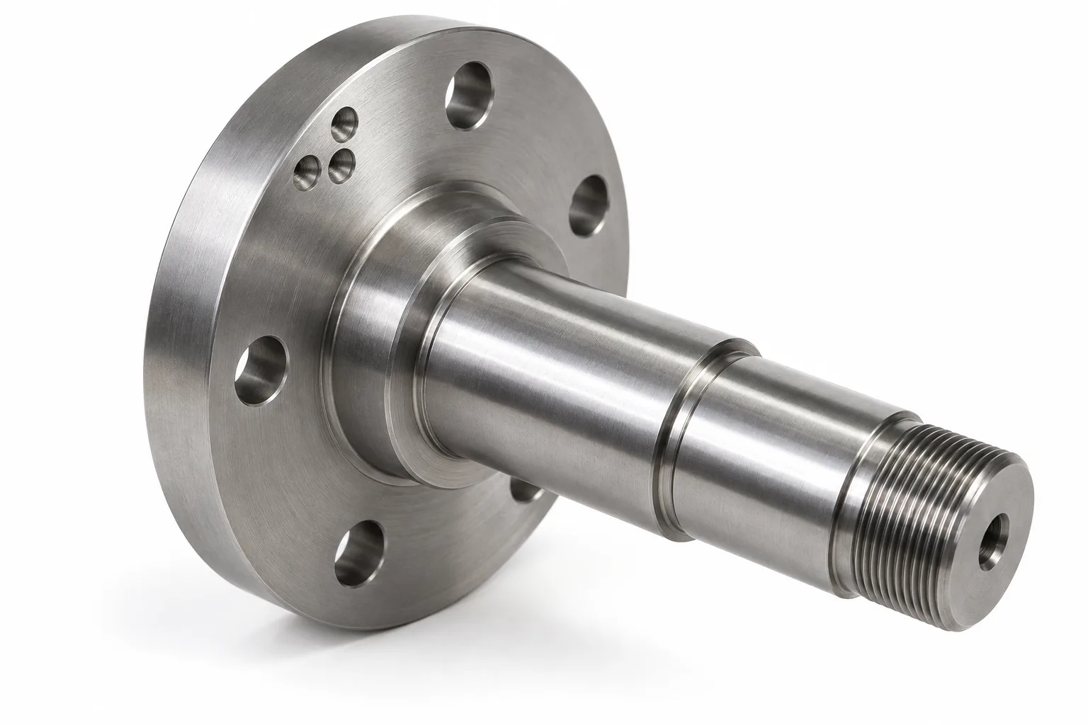
AI-generated illustration of a generic correction area. It is not a validated correction design or dimensional instruction.
Plan The Manufacturing Sequence
Balancing should occur at an agreed stage that reflects the specified final rotor condition.
Review machining, heat treatment, grinding, coating and assembly before deciding the sequence. Later operations can change material distribution or mounting conditions. Decide which operations must be complete before final balance verification.
For example, a shaft balanced before installation of its final hub represents an earlier configuration. Its report should not silently stand in for final assembly acceptance.
Coordinate balance corrections with cleaning and surface protection. Remove loose debris and address sharp edges according to the drawing. Check that correction work has not damaged nearby functional surfaces.
Include any required dimensional reinspection after correction. Your quality plan should identify the affected features and acceptance criteria. Do not assume a passing balance result replaces final dimensional inspection.
Define the handling condition after acceptance. Protect critical journals and preserve matched-part identification during packing. Record any restrictions on disassembly before delivery.
Discuss these steps during quotation, especially when several suppliers share the manufacturing route. Assign one owner for the final configuration and acceptance record.
Request A Traceable Balance Report
A useful balance report identifies what was tested, how it was tested and whether it met the agreed requirement.
Ask for the part number, drawing revision and component or assembly identification. Include a serial number or batch reference appropriate to your traceability needs.
The report should describe the rotor configuration and relevant mounted components. Record the agreed key convention, support arrangement and test speed. Include the rotor mass when it forms part of the acceptance calculation.
Request the applicable criterion and units. Where appropriate, distinguish initial readings from final residual-unbalance results. Identify the relevant planes and the allocation of acceptance limits.
The report should state the acceptance outcome clearly. A machine printout containing unexplained numbers is not enough for a buyer to review.
Agree how corrections are recorded. You may need correction locations, methods and verification after adjustment. The level of detail should match your design risk and order requirements.
If measurement uncertainty or verification checks matter to acceptance, specify them before testing. Also agree the required approval and record-retention arrangements. Do not invent those requirements after shipment.
Connect this report with your other shaft inspection records. Keep dimensional, material and balancing records identifiable without presenting them as equivalent evidence.
Prepare A Clear RFQ
Your RFQ should describe the balancing scope alongside the shaft drawing and delivery requirements.
Send the drawing revision, rotor configuration, material, quantities and expected annual volume. Add operating conditions, acceptance criteria, correction restrictions and required documentation.
Identify which components you will supply for the balancing operation. Include their availability and whether they are production parts or approved substitutes. Unavailable mating components can prevent the intended test configuration.
Ask your supplier to confirm the proposed route, equipment suitability and any external processing. Do not assume balancing is performed in-house. Resolve subcontracting and responsibility requirements during quotation.
Cost depends on more than the selected grade. Rotor size, setup, handling, assembly condition, correction access and reporting affect the work. Repeated configurations may also require different preparation from a single prototype.
TOPSHAFT’s drawing-based shaft manufacturing enquiry should identify balancing as a specific requirement. The applicable process, capability and documentation scope need confirmation for your project.
Use the CNC turning and features overview to define the machined geometry. Then request explicit confirmation of the balancing scope instead of assuming it follows automatically.
Frequently Asked Questions
Your balancing specification should resolve these questions before the supplier starts production.
Does Every Shaft Need Balancing?
Not necessarily. Your engineering team should decide from the rotor configuration, operating conditions and application requirements. Avoid imposing an unsupported universal requirement.
Does Low Runout Prove Good Balance?
No. Runout and balance assess different characteristics. Specify and verify both separately when your design needs them.
Can I Specify Only A Balance Grade?
A grade alone may leave the configuration and calculation inputs unclear. Include the applicable standard, rotor condition and relevant operating data.
Should I Balance The Bare Shaft Or Complete Assembly?
Specify the configuration relevant to your acceptance requirement. Identify who performs final assembly verification when different suppliers deliver individual components.
Is Balancing Test Speed Always Operating Speed?
No. The appropriate test speed depends on the agreed procedure and rotor behavior. Ask your supplier to confirm its basis.
Can The Supplier Drill Anywhere To Correct Balance?
No. Corrections need engineering-approved locations and restrictions. They must preserve the drawing’s dimensional, functional and structural requirements.
Should The Report Include Before And After Results?
Request them when they support your quality review. Always require identifiable final results and comparison with the agreed acceptance criterion.
What Should I Send For A Quotation?
Send drawings, quantities, rotor configuration, operating conditions, acceptance requirements, correction restrictions and documentation expectations. Identify any customer-supplied assembly components.
Send Your Rotor Requirements For Review
Define the tested configuration before selecting a balancing requirement. Keep geometry, correction restrictions and acceptance records connected. Contact us with your drawing and rotor requirements to confirm the manufacturing and balancing scope before ordering.