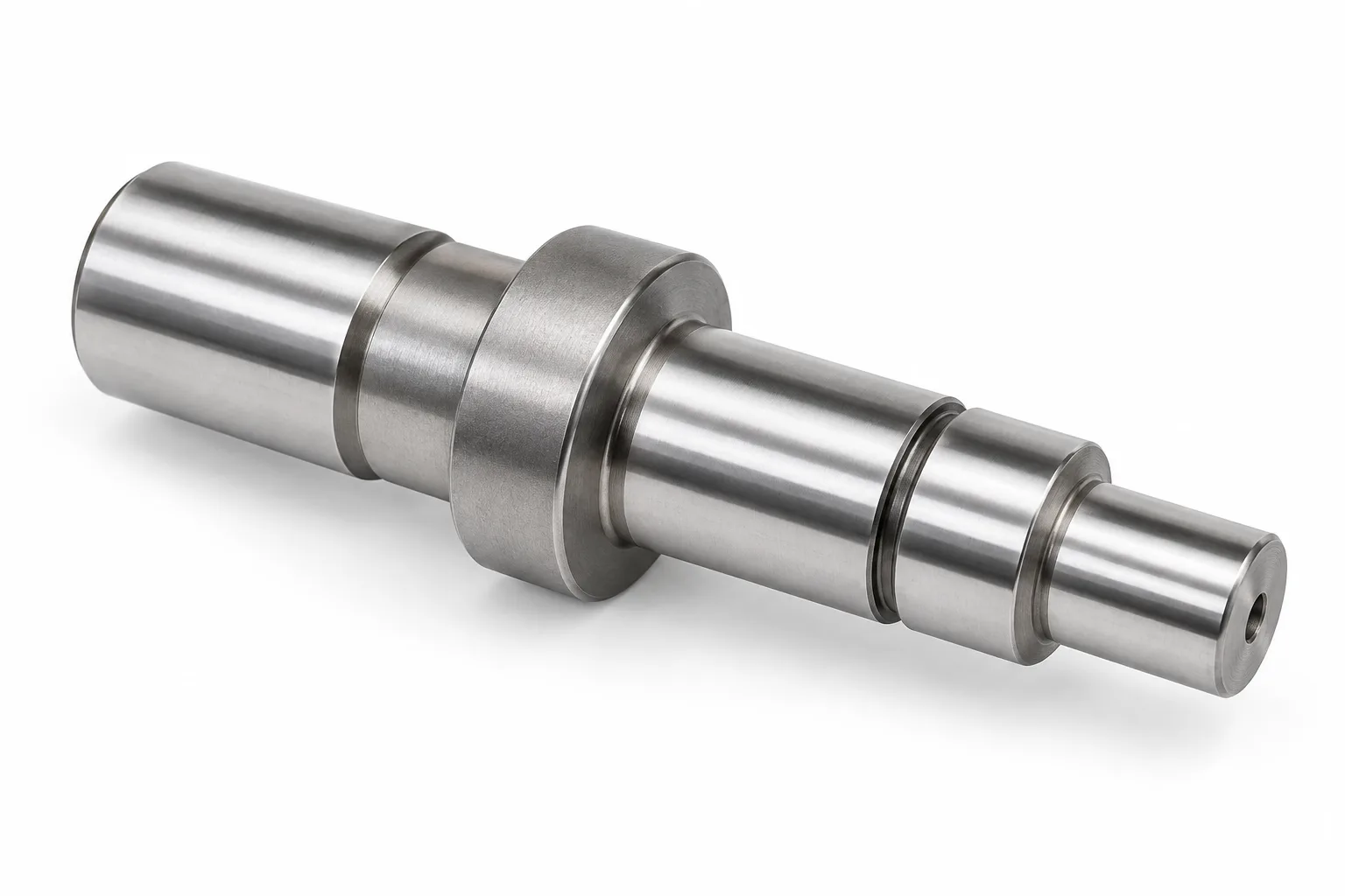
Stepped Tool Steel Shafts
Shoulders, locating diameters and ground journals support defined bearing and assembly relationships. Plan transition radii and final grinding access before hardening.
Review shaft geometry
PRECISION HARDENED SHAFT MANUFACTURING
Topshaft provides drawing-based CNC machining solutions for custom tool steel shafts used in wear-sensitive industrial machinery and tooling applications. We review material grades, heat-treatment requirements, critical shaft geometry and final inspection specifications to develop practical manufacturing solutions for OEM projects.
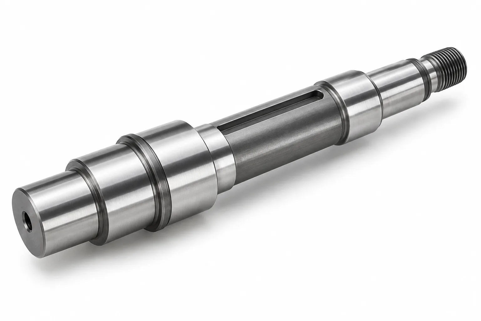
Material options subject to sourcing and feasibility confirmation.
Tool steel shafts are custom-machined mechanical components manufactured from tool steel grades selected for hardness, wear resistance, toughness, thermal performance or dimensional stability. They are used in specialized industrial mechanisms where conventional shaft steels may not provide the required surface or material performance.
Choose tool steel when a defined wear or tooling duty justifies it—not simply because a higher hardness is available. Shock, fatigue, contact lubrication and the mating component can be as important as abrasive wear. A finished shaft must satisfy its complete load path and assembly requirements.
Possible geometries; grade suitability depends on the application. No listed shape guarantees that every tool steel grade is appropriate.
Shoulders, locating diameters and ground journals support defined bearing and assembly relationships. Plan transition radii and final grinding access before hardening.
Review shaft geometry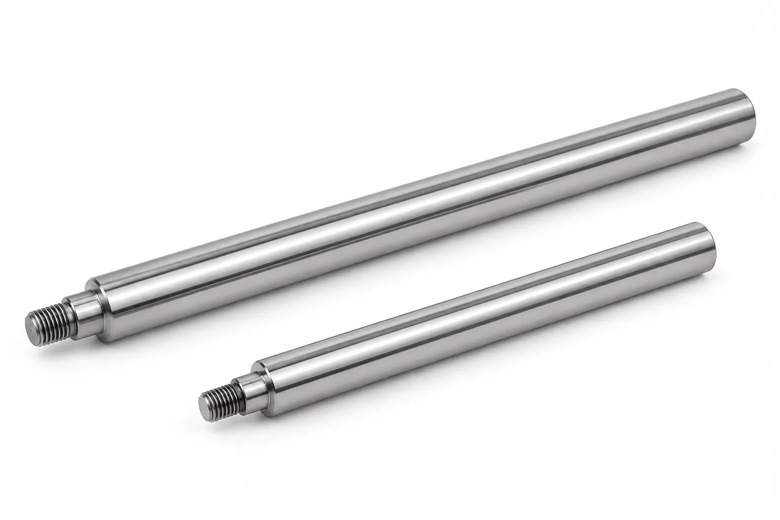
Wear-sensitive guide and positioning mechanisms need controlled straightness, surface finish and contact behavior. Match the hardened surface to the bushing, lubrication and duty cycle.
Review shaft geometry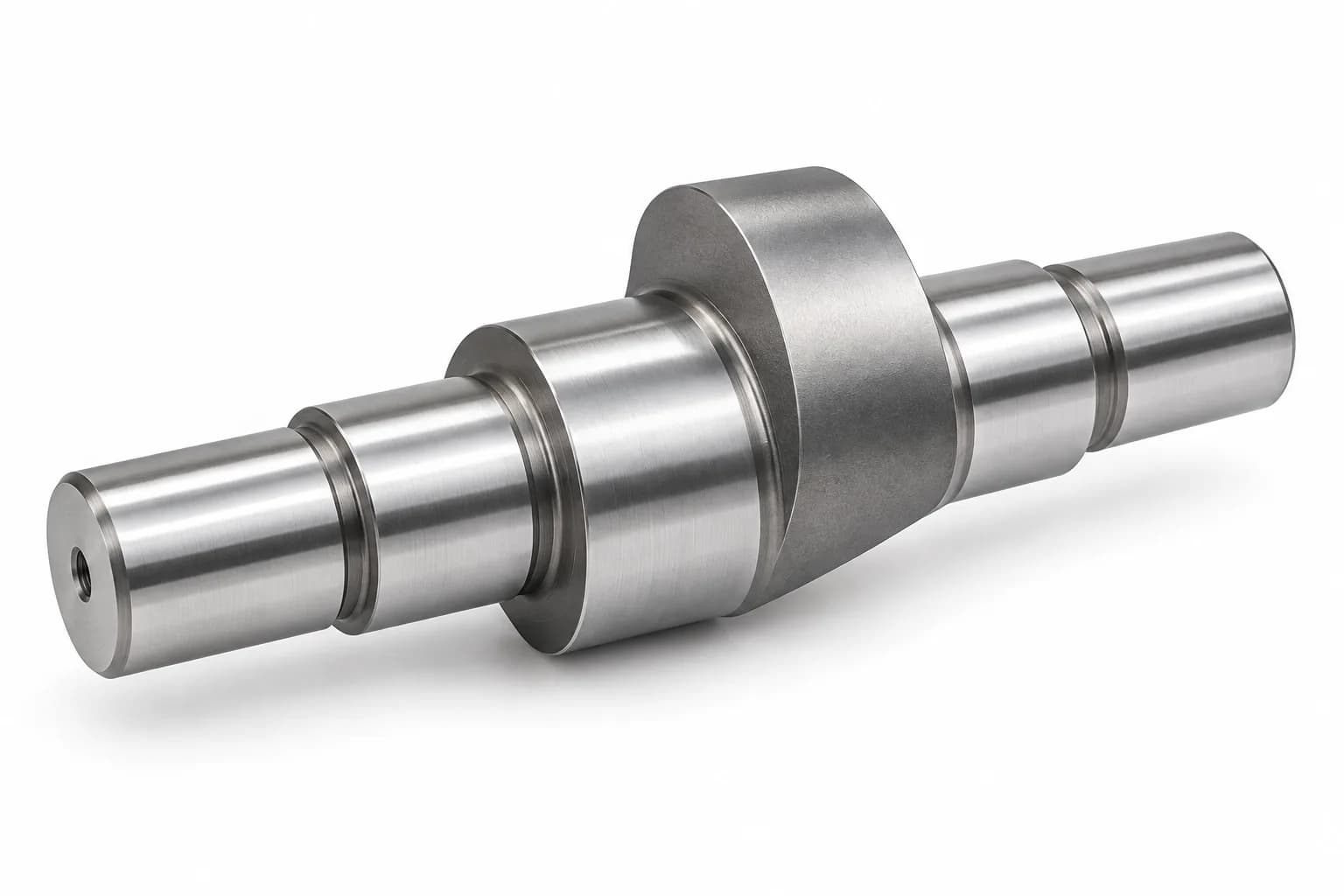
Offset journals and special profiles create controlled mechanical movement. Identify angular relationships, datum axes and profile inspection requirements for the finished hardened component.
Review shaft geometry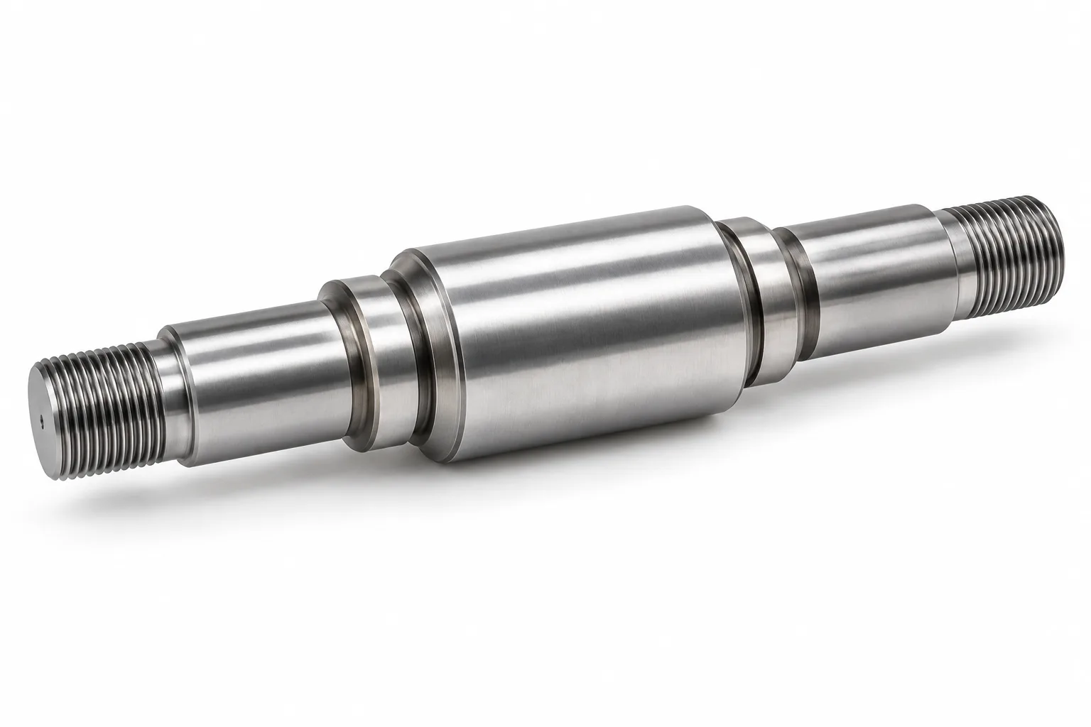
Custom threads and assembly features need suitable reliefs and a defined acceptance condition. Consider thread-root stresses and whether cutting or finishing occurs before or after hardening.
Review shaft geometry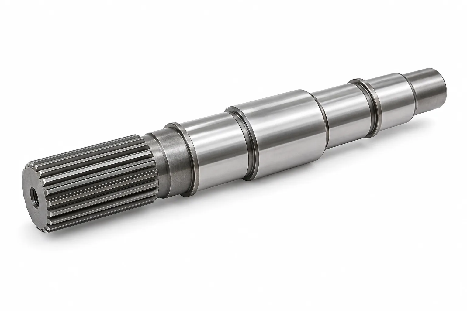
Specialized torque-transfer interfaces require a suitable grade, tooth geometry and treatment route. High hardness cannot replace assessment of cyclic torque, impact and spline-root fatigue.
Review shaft geometry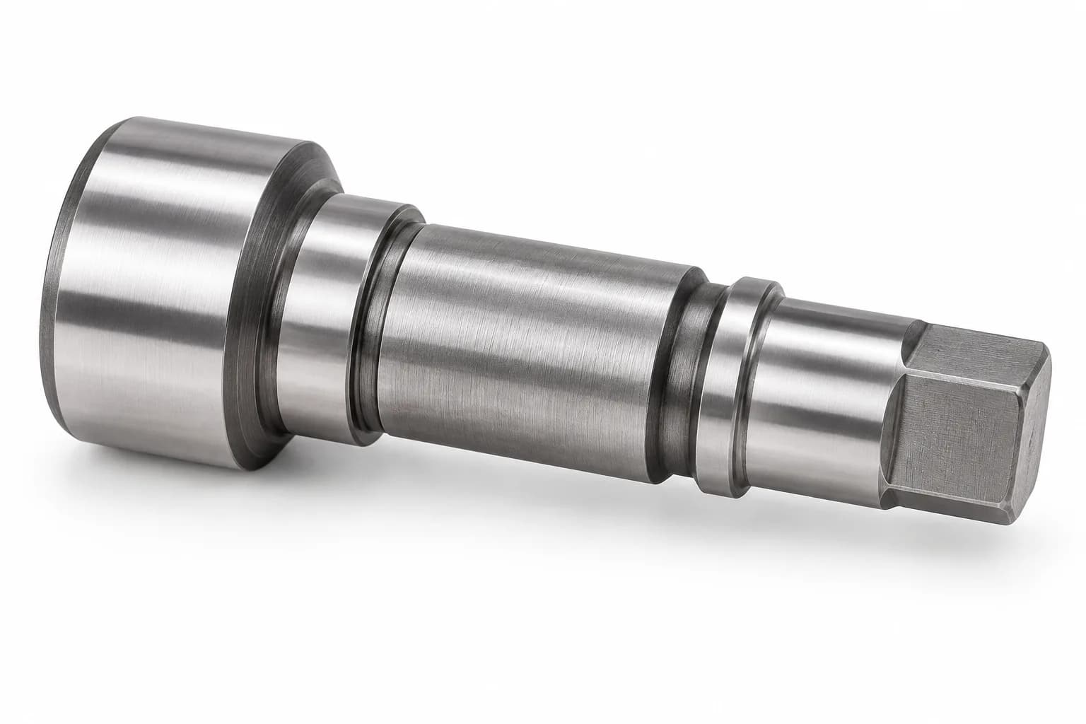
Application-specific hardened functional surfaces can combine precision journals, locating features and custom drive ends. Specify which surfaces carry wear, which carry load and how each is inspected.
Review shaft geometryAbrasive wear priority
Wear–toughness balance
Oil-hardening route
Hot-work requirements
Swipe horizontally to read all columns.
| Grade | Main characteristics | Potential applications | Design consideration |
|---|---|---|---|
| D2 | High-carbon, high-chromium cold-work tool steel with strong abrasive wear resistance. | Wear-sensitive shafts and tooling components. | Relatively limited toughness under impact loading; review torsional shock and fatigue. |
| A2 | Air-hardening cold-work tool steel balancing wear resistance and toughness. | Precision tooling shafts and mechanical components. | Heat-treatment distortion still requires control; air hardening does not mean zero movement. |
| O1 | Oil-hardening tool steel with useful machinability in the annealed condition. | Small tooling shafts, locating and mechanical components. | Quenching distortion must be considered, especially with slender or asymmetric features. |
| H13 | Hot-work tool steel with useful hot strength and thermal-fatigue resistance. | Specialized high-temperature tooling mechanisms. | Review treatment, operating temperature and actual loading; not a universal hot-service shaft. |
| S7 | Shock-resistant tool steel with relatively high toughness. | Impact-loaded tooling components where the design supports its use. | Abrasive wear resistance is lower than some high-carbon grades; specialist review required. |
| M2 | High-speed steel with high hot hardness and wear resistance. | Specialized wear-resistant rotating tooling. | Consider cost, brittleness, machining and grinding difficulty; not a default transmission steel. |
D2, A2, O1 and H13 are principal review directions; S7 and M2 are specialist alternatives. Hardness depends on treatment, section size and specified condition. There is no universal hardness number for each grade, and no permanent-stock claim is implied.
See Uddeholm cold-work tooling guidance, BÖHLER H13 background, Carpenter S7 and BÖHLER M2 background. These are material references, not supplier endorsements or evidence of Topshaft inventory.
Annealed-state machining creates the main geometry; hardened-state finishing establishes selected final functional surfaces. The sequence matters.
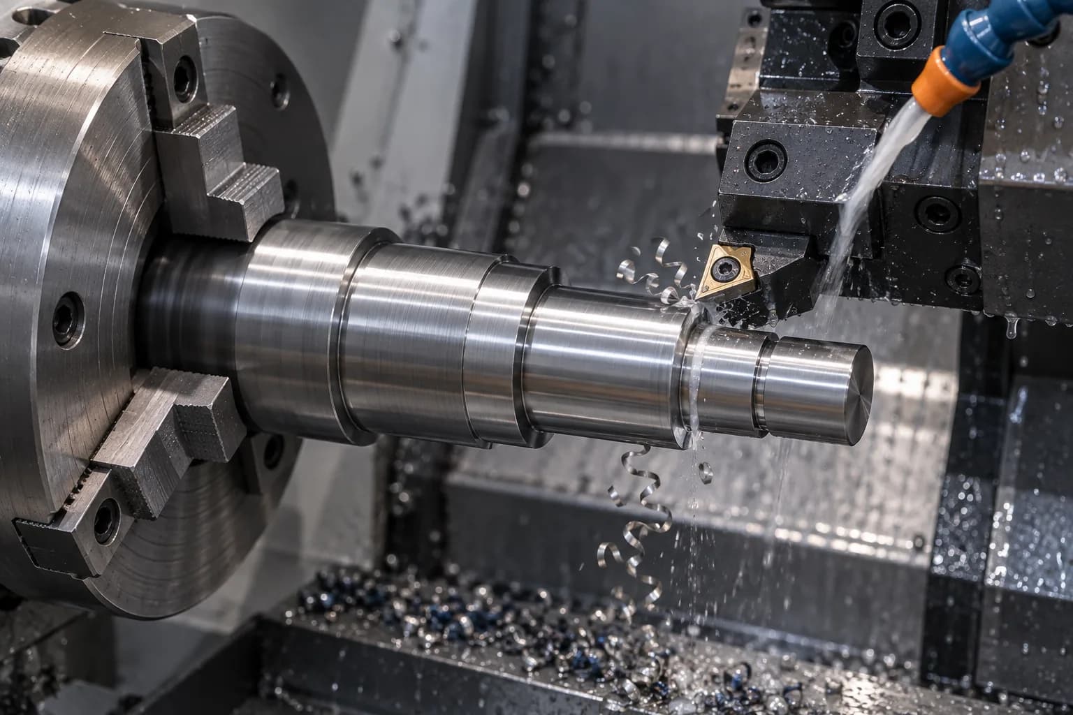
Machine annealed material to establish shaft diameters, shoulders, grooves and profiles. Rigid support, planned datums and retained grinding stock help prepare the part for subsequent hardening.
Related capability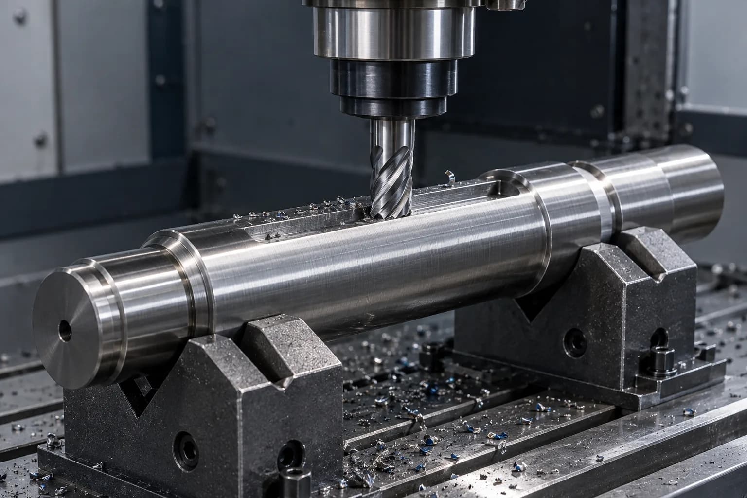
Produce keyways, flats, slots and complex mechanical features at an appropriate stage. Sharp internal corners and thin sections need review for stress concentration and heat-treatment movement.
Related capability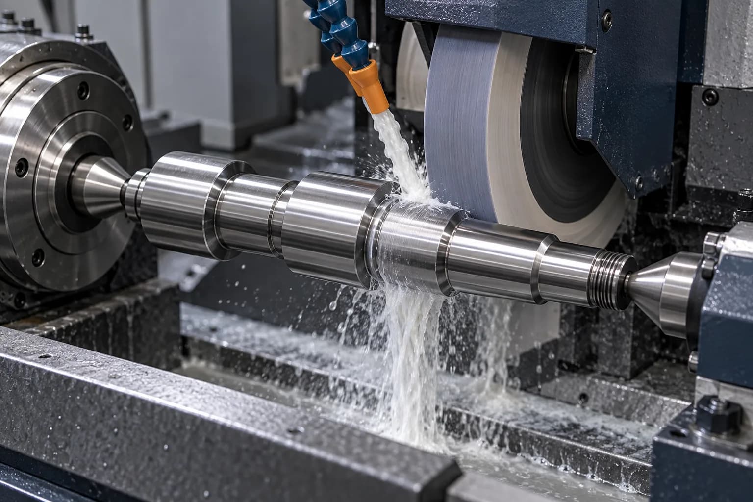
Finish critical bearing journals and functional surfaces after the specified heat treatment. Wheel selection, dressing, coolant and support are planned around hardness, carbide content and geometry.
Related capability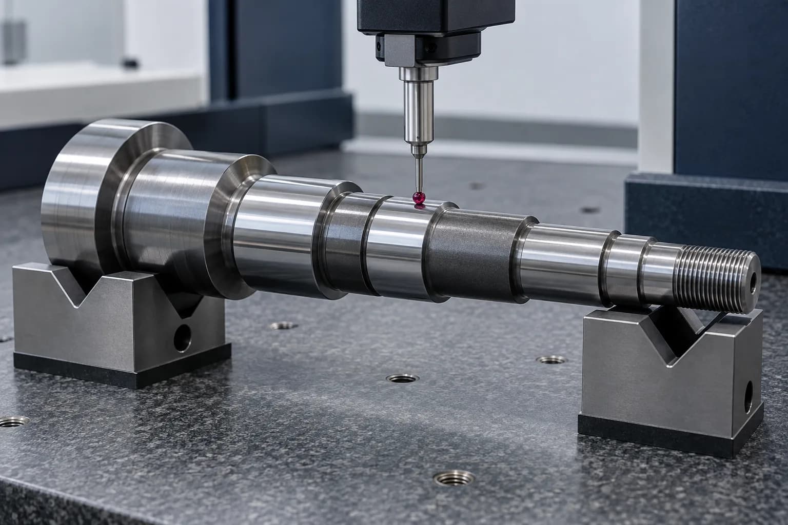
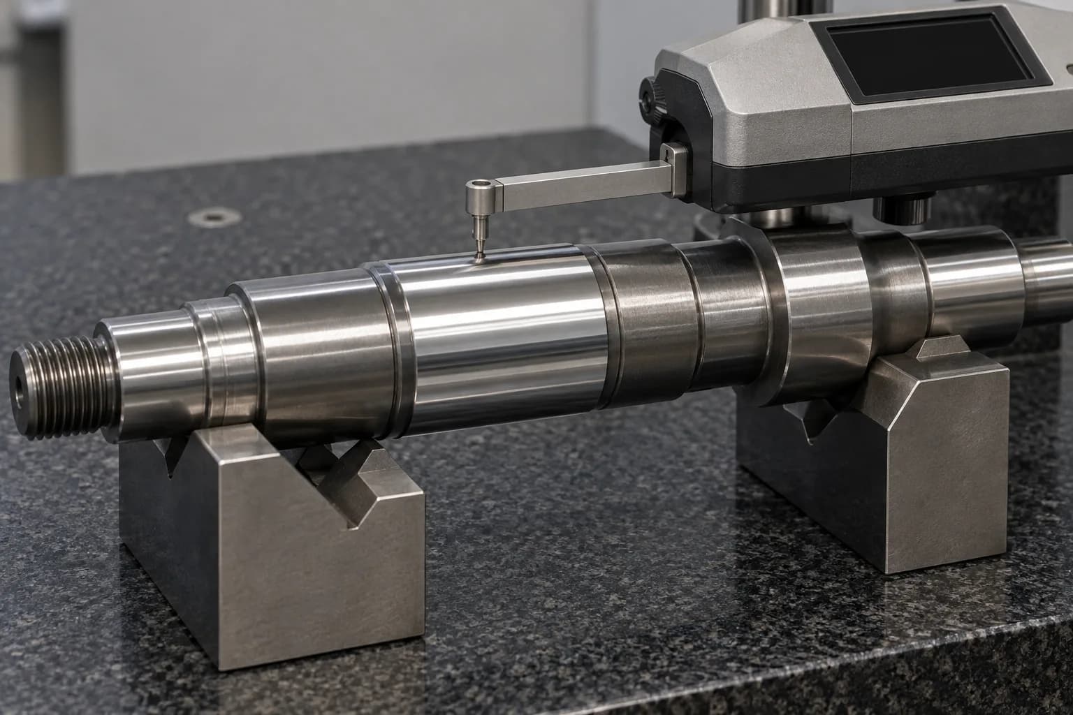
Verify drawing dimensions, geometry and hardness requirements using an agreed inspection plan. Intermediate checks support the process; final acceptance refers to the finished, specified condition.
Related capability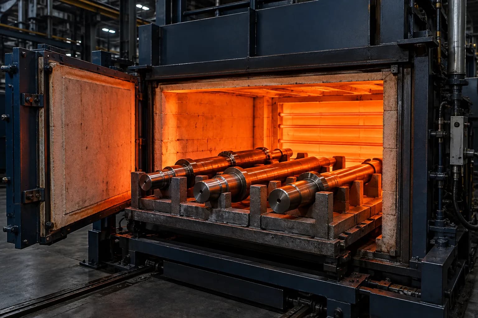
Tool steels require grade-specific procedures. Initial condition, section, furnace atmosphere, quench severity and tempering influence the final properties and dimensional movement.
Agree the required hardness and treatment specification before machining. A common thermal cycle cannot be applied to every grade, and cryogenic treatment is not universally necessary.
Swipe horizontally to read all columns.
| Process | Purpose | Engineering considerations |
|---|---|---|
| Annealing | Improve machinability and prepare material for processing. | Confirm the initial material condition and grade-specific procedure. |
| Hardening | Develop specified hardness and mechanical properties. | Austenitizing, atmosphere and quenching depend on grade, section and geometry. |
| Tempering | Adjust hardness, toughness and stability after quenching. | Temperature and number of cycles follow the grade and required properties. |
| Stress relieving | Reduce residual stresses at appropriate process stages. | Plan after rough machining where needed to reduce subsequent distortion. |
| Cryogenic treatment | Reduce retained austenite in selected applications. | Use only where technically justified; integrate with the specified tempering route. |
| Final grinding | Restore critical dimensions and surface finish. | Reserve adequate allowance before hardening and inspect the finished surfaces. |
For general background, see Uddeholm's heat-treatment guidance. Use the selected grade's specified procedure and agreed acceptance requirements for the project.
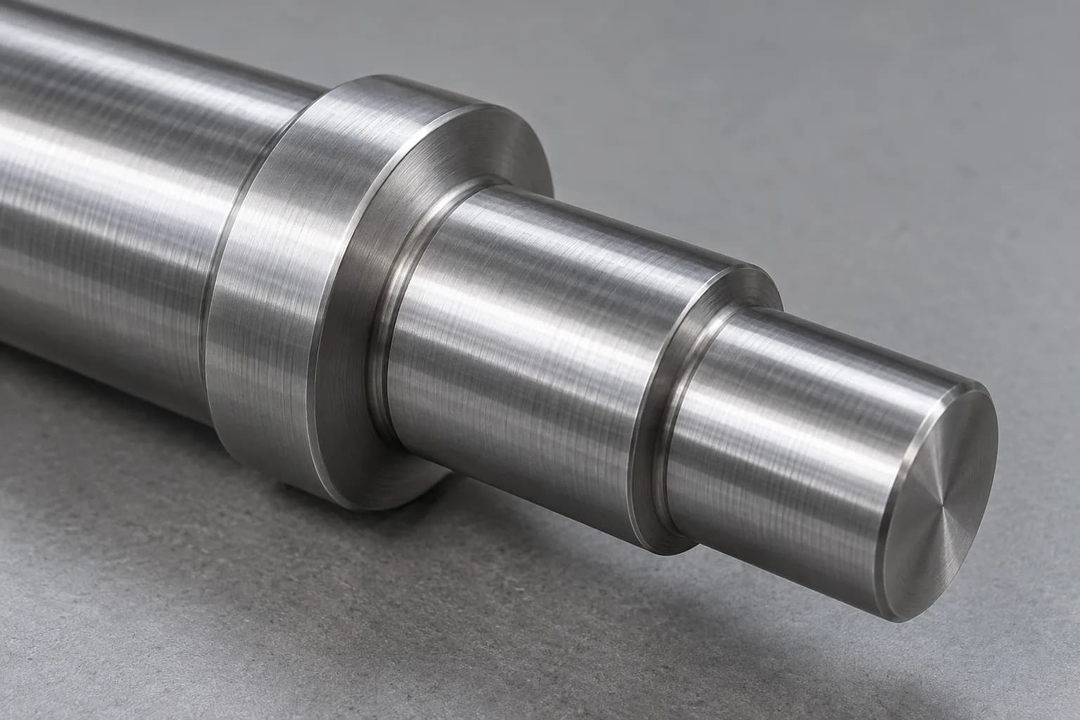
Coatings or surface treatments require compatibility review with the grade, heat-treated condition, contact duty and dimensional allowance. Process temperature must not undermine the required substrate properties. Uddeholm's grinding guidance explains why wheel condition, cooling and surface integrity matter.
A general ±0.005 mm machining claim is not a guaranteed final tolerance for every hardened tool steel shaft. Evaluate each critical feature after the complete manufacturing route.
Swipe horizontally to read all columns.
| Specification | Drawing-based requirement |
|---|---|
| Material grades | D2, A2, O1, H13 and other specified grades, subject to sourcing and feasibility review. |
| Starting condition | Annealed or drawing-specified condition; identify product standard and traceability requirements. |
| Shaft diameter | Confirmed after drawing, workholding and machine-capacity review. |
| Shaft length | Evaluated against geometry, support, slenderness and distortion risk. |
| Dimensional tolerance | Drawing-specific, subject to process and final-condition feasibility. |
| Hardness | Specified HRC range, test locations and acceptance method according to grade and treatment. |
| Geometric tolerances | Runout, straightness, roundness, cylindricity and coaxiality referenced to defined datums. |
| Surface finish | Drawing-defined roughness and relevant lay, especially for bearing or sliding surfaces. |
| Documentation | Material, heat-treatment and inspection records as agreed before production. |
Define wear mechanism, contact pressure, impact and load reversals before selecting hardness. A harder but less damage-tolerant grade may fail by chipping or cracking rather than gradual wear.
Review shoulders, spline roots, keyways, threads and cross-holes under combined torsion and bending. Specify generous feasible transitions and surface requirements without interfering with mating parts.
Slender lengths, asymmetric removal and section changes influence movement. Coordinate rough machining, stress relief, support and intermediate checks rather than expecting final geometry to survive hardening unchanged.
Reserve material on critical surfaces and provide wheel access and reliefs. Too little stock prevents correction; excessive removal increases cycle time and thermal risk. Set feature-specific allowances.
Identify bearing seats, sliding lands, seals and assembly interfaces individually. Give datums, fits, roughness, edge requirements and the final treatment condition so inspection reflects real function.
Potential uses, not claims of delivered projects or validated service life.
Precision tool shafts and locating components. Review wear mechanism, alignment and replaceable mating surfaces.
Wear-sensitive guide and positioning shafts. Review straightness, lubrication, contact pressure and repeat motion.
Specialized hardened mechanical components. Review impact, temperature cycles and fatigue at geometry transitions.
High-wear motion and positioning mechanisms. Review duty cycle, cleanliness, friction and counterface compatibility.
Custom shafts requiring hardened functional surfaces. Review the complete load path, journal fits and acceptance condition.
Specialized precision shafts and fixtures. Review loading direction, repeatability and documented geometric checks.
Swipe horizontally to read all columns.
| Factor | Tool steel | Alloy steel | Stainless steel |
|---|---|---|---|
| Primary selection driver | Hardness, wear or specialized tooling performance. | Strength, toughness and fatigue resistance. | Corrosion resistance and grade-specific mechanical performance. |
| Hardening capability | Often high; grade and thermal route determine the result. | Broad range depending on grade and treatment. | Grade-dependent; austenitic, martensitic and precipitation-hardening families differ. |
| Toughness | Varies; some grades are relatively brittle at selected conditions. | Often advantageous for loaded shafts with an appropriate condition. | Varies by grade, condition and temperature. |
| Machining cost | Often higher after hardening, with additional grinding needs. | Grade-, condition- and geometry-dependent. | Grade-dependent; work hardening and tool wear can affect cost. |
| Typical shaft application | Wear-sensitive specialized components. | Transmission and high-load shafts. | Corrosion-sensitive shafts where the grade suits the environment. |
Select the material family by failure mechanism, operating environment and total finished-part requirements. These comparisons are qualitative; they do not establish a universal ranking for every grade or condition.
Check relevant journals in the final condition using methods appropriate to the tolerance. Diameter readings alone do not establish all form requirements.
Use the drawing's datum and support scheme. Agree whether acceptance concerns the shaft axis, individual journals, functional mounting or another stated reference.
Measure the specified surfaces with the required parameters and evaluation conditions. Visual polish is not a substitute for a defined roughness result.
Confirm the specified range, test method and suitable locations. Coordinate any indentation restrictions on ground functional surfaces with the inspection plan.
Inspect connection features, reliefs, fits and critical angular relationships. Include requirements that remain difficult to correct after hardening.
Agree required material identity, heat or lot references, treatment records and inspection reports. Record availability and scope during quotation, not after production.
Start with the controlled drawing and application rather than a generic hardness claim. Identify material identity, final condition, load-sensitive features and the evidence needed for acceptance.
Coordinate turning, milling and connection features around functional datums. Review workholding, slenderness and machining access before establishing the route for a custom tool steel shaft.
Plan the transition from annealed machining to hardening and final grinding. Allowances, reliefs, distortion checks and treatment compatibility are considered together, subject to project confirmation.
Translate the drawing into agreed dimensional, geometric, surface and hardness checks. Define report scope and traceability expectations early to support clear OEM procurement and repeat ordering.
TOPSHAFT is the precision shaft manufacturing division of Dongguan Tops Precision Manufacture Co., Ltd., operating alongside Topsbest Precision for shaft-focused OEM projects. Review company information and the Custom Shaft manufacturing scope. Request project-relevant production evidence; no customer case or inspection result is asserted here.
Direct answers on grades, hardening, shaft geometry and quotation requirements.
D2, A2, O1 and H13 are common grades to evaluate; S7 and M2 are specialist alternatives. They address different wear, impact and temperature requirements, not interchangeable performance levels. Specify the product standard, supplied condition, final heat treatment and acceptance requirements. Availability and suitability for a particular shaft geometry must be confirmed during drawing review.
D2 can suit selected wear-sensitive rotating components, but it is not a universal high-load shaft material. Its abrasive wear resistance comes with limited toughness relative to tougher alternatives. Review bending, cyclic torsion, shock, notches and failure consequences. A suitably heat-treated alloy steel or another tool steel may be preferable when impact or fatigue dominates over abrasive wear.
D2 generally emphasizes abrasive wear resistance, while A2 offers a different balance of wear resistance and toughness. Grade selection still depends on the specified treatment, section and service conditions. Neither eliminates distortion or grinding requirements. Compare the likely failure mechanism, critical geometry and complete finished-part cost instead of selecting solely by nominal hardness or chromium content.
Yes, selected hardened features can be finished by grinding or suitable hard-machining methods when the grade, hardness and geometry permit. This is different from ordinary annealed-state turning and milling. Tool access, rigid support, wheel or insert selection and surface integrity need review. Plan pre-hardening stock and final datums rather than assuming every feature can be corrected afterward.
Achievable hardness depends on the grade, heat-treatment cycle, section size and required property balance. There is no single HRC value appropriate to all tool steel shafts. Specify an acceptable range, test method, locations and final condition. The quotation should confirm feasibility; hardness alone does not prove toughness, fatigue resistance, dimensional stability or suitability for the actual operating duty.
Heat treatment can change straightness, size and runout through thermal gradients, phase transformation and stress redistribution. Slender or asymmetric shafts need particular attention. A coordinated route may include staged machining, stress relief, controlled treatment, intermediate checks and reserved final grinding stock. The extent of correction and final acceptance must be evaluated for the actual grade, geometry and drawing datums.
Topshaft accepts drawing-based inquiries for custom finished tool steel shafts. Send the controlled drawing or model, grade, starting condition, treatment and inspection requirements for technical review. Manufacturing feasibility, material sourcing, critical tolerances and documentation are confirmed for the project. A listed shaft geometry or steel grade does not imply that every combination is suitable or permanently available.
Provide the drawing revision, material grade and standard, starting condition, required hardness, heat-treatment specification and quantity. Mark critical fits, datums, geometric tolerances, surface finish and functional edges. Include inspection documents, application loads or wear conditions and delivery expectations. Send supporting CAD files where useful; identify any unresolved requirements so assumptions can be discussed before quotation and production.
Send the buyer's drawing, material grade, starting condition, required hardness, heat-treatment specification, critical tolerances, surface finish and quantity. Include inspection documents and delivery expectations for a finished-component quotation.