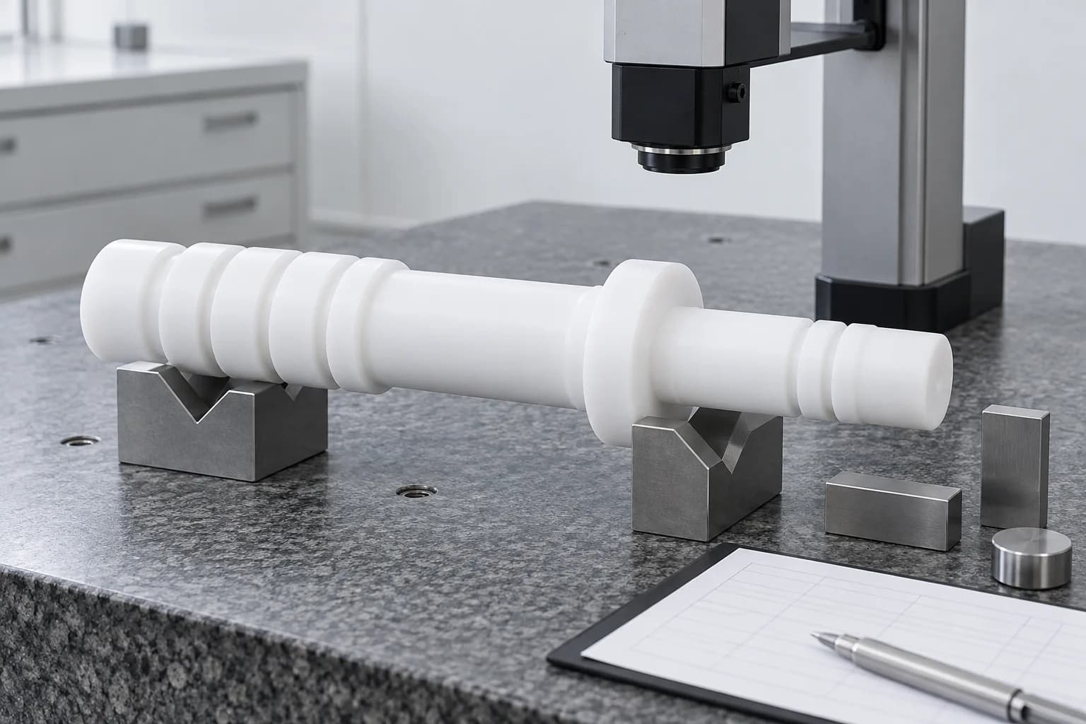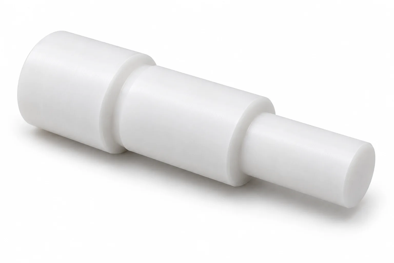
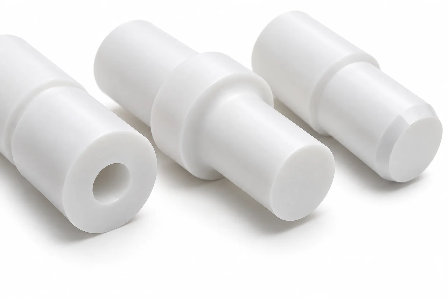
Stepped PTFE Shafts
Multiple diameters and shoulders for specialized assemblies. Define locating faces, transitions and the functional axis while checking the stiffness of the remaining section.
Review shaft geometry
PRECISION ENGINEERING PLASTIC SHAFTS
Topshaft provides custom CNC machining solutions for PTFE shafts used in chemical-resistant, low-friction and specialized industrial applications. We manufacture drawing-based components with stepped profiles, grooves, threads and other precision features, subject to material and design feasibility review.
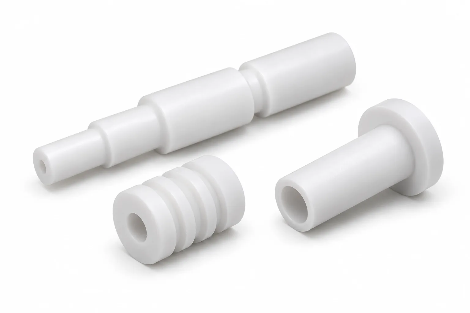
PTFE shafts are custom-machined cylindrical components made from polytetrafluoroethylene, a fluoropolymer known for its chemical resistance, low coefficient of friction and electrical insulation properties. They are used in selected industrial applications where conventional metallic components may be unsuitable because of chemical exposure or electrical requirements.
A PTFE plastic shaft is not generally a direct replacement for a highly loaded steel rotating shaft. Low stiffness, creep and sustained-load sensitivity make support, geometry and actual service conditions essential. This service is for finished drawing-based components, not standard rods or raw plastic stock.
PTFE is the generic polymer name. Teflon is a trademark associated with Chemours fluoropolymer products; not every PTFE shaft is supplied from Teflon-branded material. State the exact grade or brand requirement when requesting a quote. Chemours provides brand-use information.
Potential custom geometries, not a guarantee that every design is mechanically suitable for PTFE.
Multiple diameters and shoulders for specialized assemblies. Define locating faces, transitions and the functional axis while checking the stiffness of the remaining section.
Review shaft geometry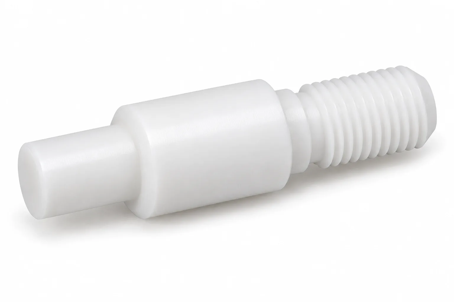
Custom threaded features for suitable low-load connections. Specify thread form, engagement and assembly force; a metal fastener's tightening torque must not be transferred unchanged.
Review shaft geometry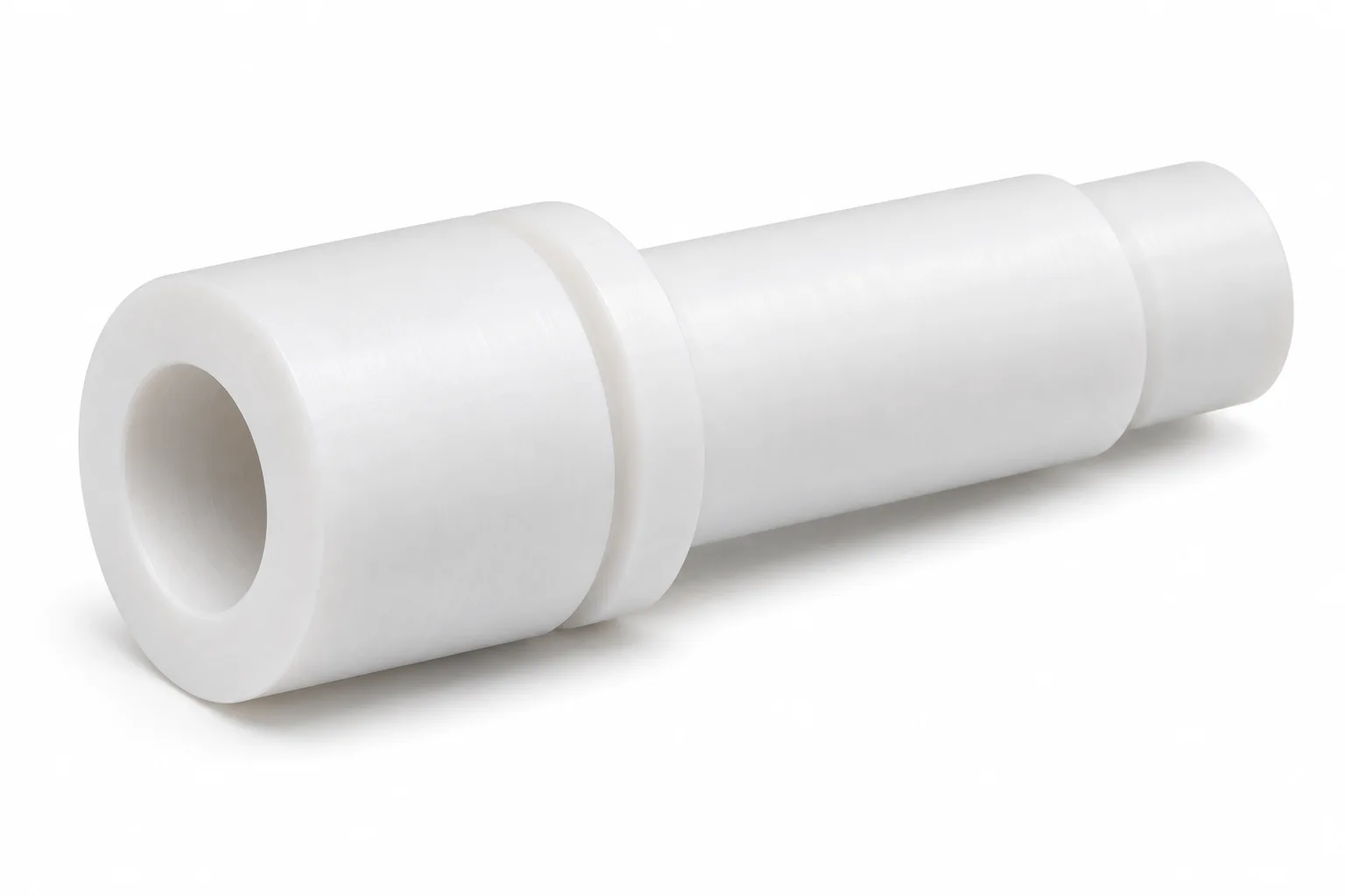
Axial bores and tubular geometries for drawing-defined passages or interfaces. Review wall thickness, bore access and the relationship between inside and outside surfaces.
Review shaft geometry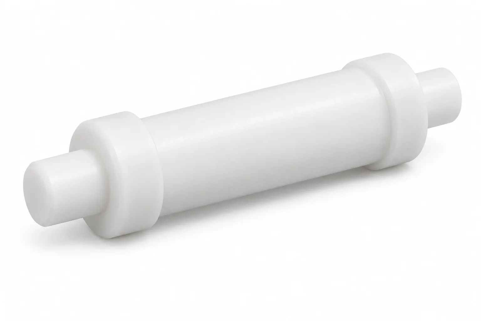
Low-load positioning and guiding components. Review unsupported length, contact pressure, sliding clearance and the mating surface before selecting PTFE for the mechanism.
Review shaft geometry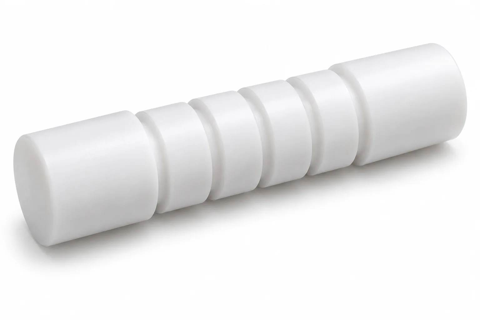
Custom grooves and retaining features for specialized interfaces. Leave sufficient section at groove roots and assess sustained contact loads rather than relying on appearance alone.
Review shaft geometry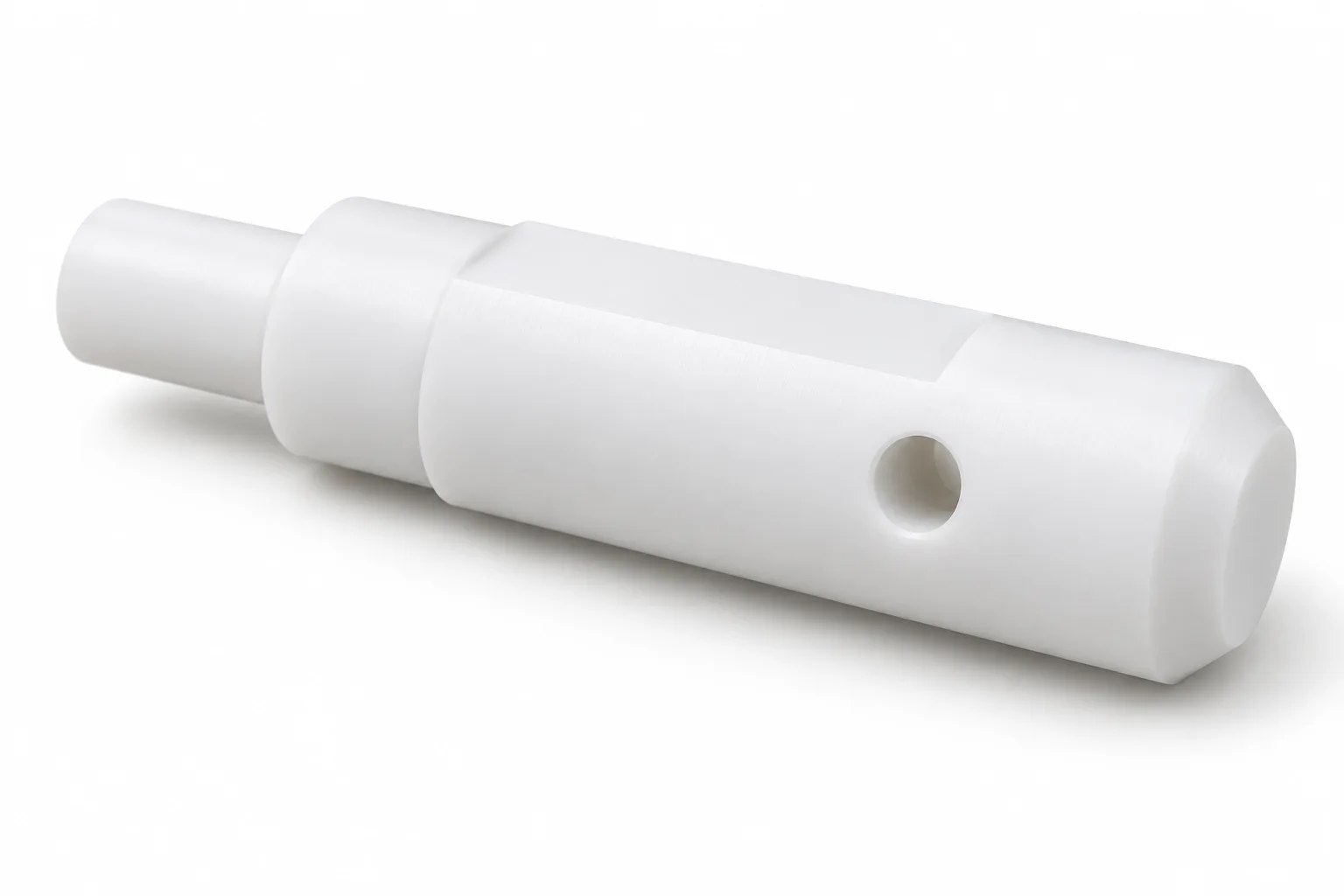
Drawing-specific machined shapes and interfaces, including flats, slots and cross holes. Keep secondary features related to the turned axis and avoid fragile unsupported details.
Review shaft geometrySwipe horizontally to read all columns.
| Material | Main characteristics | Potential applications | Engineering consideration |
|---|---|---|---|
| Virgin PTFE | Excellent chemical resistance, electrical insulation and low friction | Chemical-resistant components, electrical insulation | Relatively high creep and low stiffness |
| Glass-filled PTFE | Improved compressive behavior and wear characteristics in some applications | Sliding and bearing-contact components | Filler may affect chemical compatibility and mating-surface wear |
| Carbon-filled PTFE | Modified wear, creep and electrical behavior depending on formulation | Selected mechanical and sliding applications | Electrical properties depend on carbon content and formulation |
| Bronze-filled PTFE | Often improved wear and load-bearing behavior | Selected industrial bearing components | Bronze filler can reduce chemical compatibility |
| Graphite-filled PTFE | Modified friction and wear behavior | Specialized sliding-contact applications | Performance depends on loading and counterface |
| Modified PTFE | Formulation-dependent improvements in processing or performance | Specialized engineered components | Supplier-specific material properties must be checked |
Material selection and availability are confirmed during quotation; this is not a routine-stock list. PTFE is often used for bushings, seals and bearings, but a filled-PTFE formulation suitable for a bushing is not automatically suitable for a long, unsupported rotating shaft.
Review Röchling's PTFE material-family information and AFT Fluorotec's bronze-filled PTFE guidance as background. The supplied grade's data and agreed documentation govern selection; these references do not imply sourcing, endorsement or stock availability.
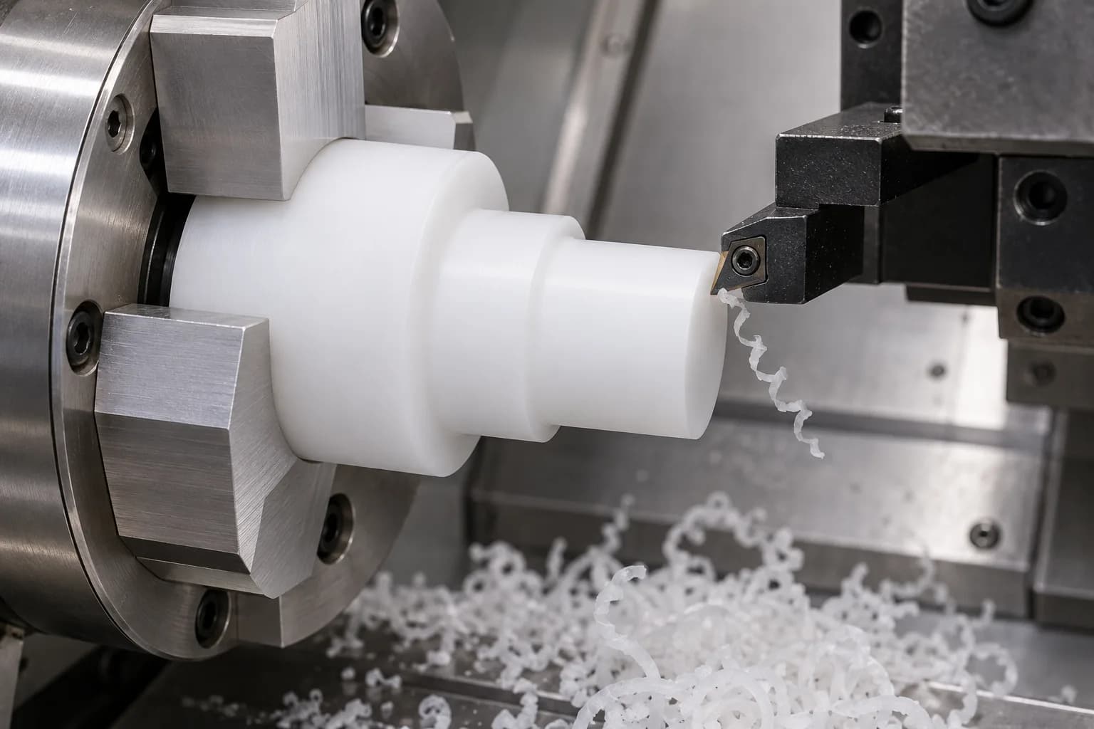
Diameters, shoulders, grooves, bores and rotational profiles are reviewed as one coordinated geometry. Sharp cutting edges and appropriate support help manage PTFE's softness and elastic movement. Control workholding pressure and heat rather than trying to force a flexible part into a metal-shaft process.
Related capability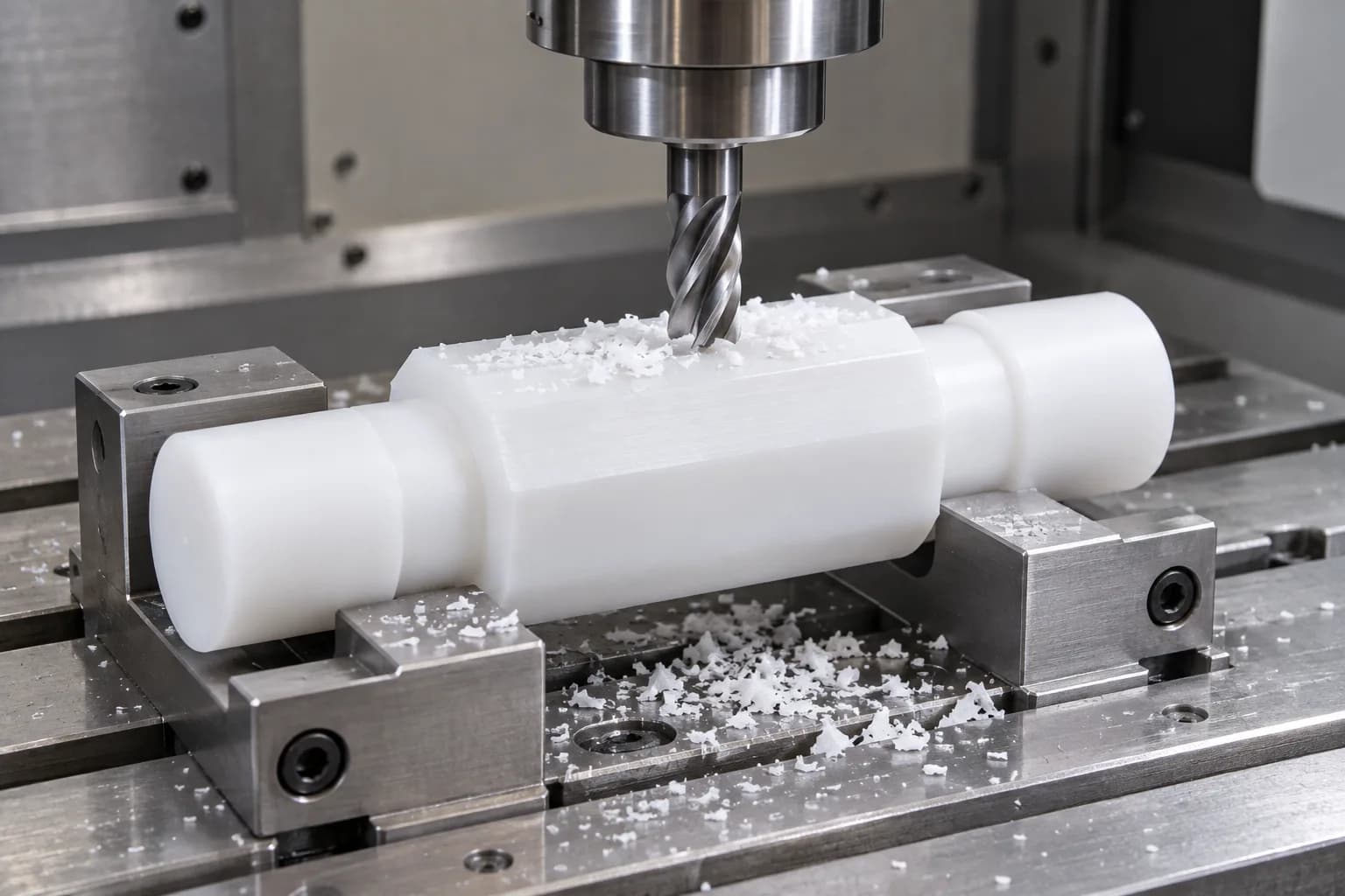
Flats, slots, cross holes and non-rotational features require supported, controlled workholding. Relate milled features to the functional journals. Thin sections can deform during clamping and recover after release; tool engagement and the machining sequence must account for that movement.
Related capability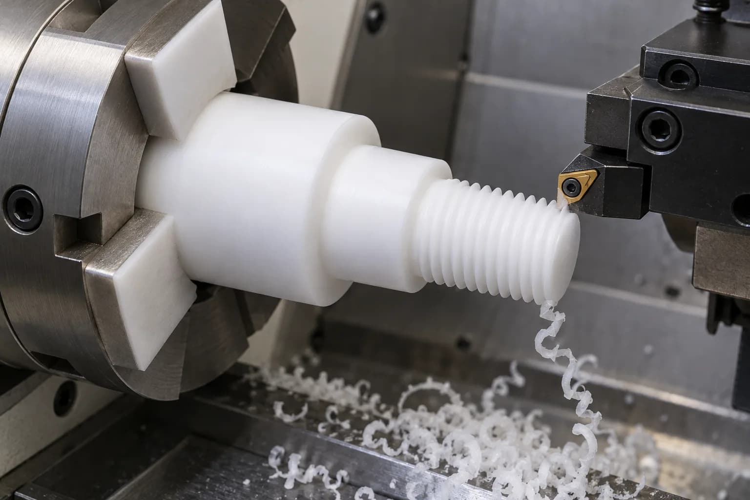
Custom threads, drilling, chamfering and controlled deburring complete the specified interfaces. Review thread engagement, remaining wall and assembly forces. Manage chip removal and burr formation without leaving loose edges, overheating a surface or damaging an adjacent sealing or locating feature.
Related capability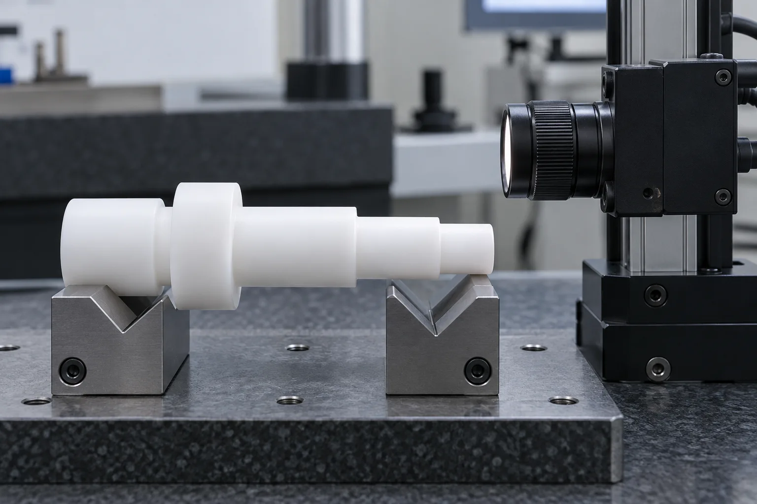
Drawing-defined diameters, lengths, geometry and functional features are checked in an agreed final condition. Allow for machining heat and post-machining dimensional recovery. Suitable measurement force, support and inspection temperature help avoid mistaking elastic compression or thermal movement for machining error.
Related capabilityPTFE shaft machining must account for material softness, elastic clamping deformation, thermal expansion, tool sharpness, burr formation and dimensional recovery. A CNC machined PTFE shaft cannot simply inherit the same general tolerances as steel. Curbell's plastics-machining guidance provides background, not a universal cutting recipe.
Swipe horizontally to read all columns.
| Specification | Drawing-based requirement |
|---|---|
| Materials | Virgin and specified filled PTFE grades |
| Shaft diameter | Drawing-based and machine-capacity dependent |
| Shaft length | Evaluated according to slenderness and stiffness |
| Dimensional tolerance | Confirmed after geometry and material review |
| Surface roughness | Application-specific, subject to machining feasibility |
| Geometric tolerances | Runout, straightness and roundness where achievable |
| Temperature requirements | Based on grade, load and exposure duration |
| Material documentation | Supplier certificates where requested and available |
| Production scope | Prototype and repeat OEM production |
PTFE can have useful temperature resistance, but mechanical strength and creep behavior are highly temperature-dependent. A published material temperature rating is not a universal safe operating limit for loaded shafts. Precision PTFE shafts require an agreed geometry, service condition and final inspection basis.
Swipe horizontally to read all columns.
| Design factor | Engineering consideration | Recommended approach |
|---|---|---|
| Creep and cold flow | PTFE can deform under sustained mechanical loading | Evaluate load, contact pressure and service duration |
| Low stiffness | Long or slender PTFE shafts may deflect significantly | Review diameter, unsupported length and shaft support |
| Thermal expansion | Temperature changes can affect dimensional fits | Define operating and inspection temperatures |
| Clamping deformation | Excessive workholding force can distort the component | Use suitable fixtures and controlled machining methods |
| Thread strength | PTFE threads can deform under high assembly loads | Evaluate thread engagement and fastening requirements |
| Wear performance | Depends on pressure, velocity, counterface and filler formulation | Select material based on actual operating conditions |
PTFE normally does not require conventional metallic coatings for corrosion protection.
Low surface energy makes adhesive bonding and coating adhesion difficult without suitable surface preparation. Anodizing, conventional steel hardening and standard metal plating are not routine PTFE finishing processes.
Potential application directions, subject to grade and engineering review—not claims of completed projects or universal compliance.
Specialized chemical-resistant components and low-load mechanisms. Identify the chemical, concentration, temperature, exposure time and cleaning agents; the filler must be compatible as well as the PTFE matrix.
Components used in selected chemically aggressive environments. Review wetted surfaces, pressure, sealing contact and mechanical loads rather than assuming a PTFE shaft can replace a highly loaded metal pump shaft.
Low-friction guide and positioning mechanisms where support and clearance are suitable. Check contact wear, dwell loads and cleaning conditions. Any food-contact requirement needs the exact grade and intended-use documentation.
Specialized insulating and chemically resistant mechanical parts, subject to application review. Define purity, particles, extractables, cleaning and packaging requirements; a generic PTFE designation does not establish semiconductor-process suitability.
Insulating components manufactured from suitable PTFE grades. Specify the actual electrical and mechanical requirements; carbon, graphite or other fillers can change electrical behavior, so family-level insulation assumptions are insufficient.
For a chemical resistant plastic shaft, describe exposure and mechanical duty together. Fluid handling links to the existing pump page; other applications link to related industrial machinery requirements where dedicated industry pages are not available.
Compare the complete duty, not one material headline. These are qualitative family-level selection directions, not acceptance limits.
Swipe horizontally to read all columns.
| Factor | PTFE | PEEK | POM / Delrin | Nylon |
|---|---|---|---|---|
| Stiffness | Relatively low; short spans and support matter | Generally stiffer; grade and temperature still matter | Useful mechanical stiffness under suitable conditions | Grade- and moisture-dependent stiffness |
| Creep | Sustained-load deformation is a key design limit | Often considered where higher mechanical demands apply | Still requires time/load review | Moisture, time and load affect performance |
| Temperature | Published rating is not a loaded-shaft service limit | High-temperature candidate with grade/load validation | Moderate-temperature mechanical applications | Evaluate grade, conditioning and service temperature |
| Chemical compatibility | Review exact chemical and any filler | Broad resistance, with chemical-specific exceptions | Exposure and cleaning chemistry need review | Chemical exposure and moisture need review |
| Sliding contact | Low friction; wear depends on contact system | Filled and unfilled grades need counterface review | Low-friction mechanical components in suitable duties | Common wear applications with conditioning review |
A PTFE vs PEEK shaft review often turns on chemical exposure, load and stiffness. A PTFE vs Delrin shaft review also needs temperature, fit and sustained-load assessment. Use actual supplier grades, contact conditions and required life rather than declaring one polymer universally better.
A drawing-based route from application review to finished custom PTFE shafts.
Confirm revision, functional surfaces, dimensions, operating loads, speed, chemicals and electrical or cleanliness requirements before committing to a route.
Agree virgin or filled PTFE, exact supplier designation, available stock form and any required material records. Resolve substitutions explicitly.
Review supports, workholding, tool access, secondary operations and the final measurement condition. Identify geometry that needs redesign or feasibility trials.
Coordinate turning, milling, drilling and threading with controlled handling. Protect thin sections and avoid carrying machining heat into the final acceptance decision.
Check the agreed dimensions and geometry after relevant thermal and dimensional recovery. Retain the inspection basis and investigate ambiguous results.
Release the agreed reports and material information, identify parts or lots, and protect finished surfaces from contamination and deformation during shipment.
Verify the agreed grade, filler designation and available supplier documentation against the order; color alone cannot establish formulation.
Inspect the specified diameters, lengths, bores, grooves and thread features in their agreed final manufacturing state.
Account for measurement temperature, machining heat and recovery. Define the acceptance condition rather than imposing an arbitrary universal waiting time.
Use suitable contact force and supports, or an appropriate non-contact method, so the measurement does not significantly distort soft PTFE.
Review achievable runout, straightness, roundness and interface relationships against the drawing, not against an unspecified steel-shaft standard.
Agree report scope and traceability, then protect clean functional surfaces without clamping or bending the shaft during packing.
Start with the actual shaft interfaces, revision and duty conditions. Identify PTFE's limitations before approving a production drawing.
Connect chemical, friction and electrical requirements with the specified formulation and sourcing review, not a generic material promise.
Review turned and secondary features as a connected manufacturing route, including support, workholding and final-condition inspection.
Agree inspection evidence, material information and delivery protection during quotation. Request project-relevant evidence when evaluating the supplier.
TOPSHAFT is the precision shaft manufacturing division of Dongguan Tops Precision Manufacture Co., Ltd., operating alongside Topsbest Precision for shaft-focused OEM projects. Review company information and request the evidence relevant to your project.
A PTFE shaft is a custom-machined cylindrical component made from polytetrafluoroethylene or a specified filled PTFE formulation. It can include steps, grooves, bores and threads for selected low-load, chemical-resistant, insulating or low-friction applications. This service concerns finished drawing-based parts, not commodity rods.
PTFE is the generic polymer name; Teflon is a trademark associated with Chemours fluoropolymer products. A buyer searching for a Teflon shaft should still specify the polymer and exact grade. Not every PTFE component is supplied from Teflon-branded material, and no brand substitution should be assumed.
PTFE can be used for certain lightly loaded rotating or positioning components where chemical resistance, low friction or electrical insulation is important. Its low stiffness and sustained-load creep make it less suitable for high-torque or heavily loaded unsupported shafts. Evaluate load, speed, temperature, support and dimensional requirements.
Choose the exact formulation against contact pressure, velocity, counterface, chemicals, temperature and electrical requirements. Glass, carbon, bronze and graphite change different properties. A formulation appropriate for a bushing is not automatically appropriate for a long rotating shaft. Confirm availability and supplier data during quotation.
Do not transfer general steel-shaft tolerances to PTFE. Softness, elastic clamping deformation, thermal expansion and dimensional recovery affect machining and measurement. Achievable tolerances and surface finish must be reviewed for the exact grade, geometry and final inspection condition before acceptance requirements are agreed.
Options include as-machined or finish-turned surfaces, controlled deburring, chamfers and edge rounding, drilling, threading and application-specific cleaning. Special treatments require review. PTFE normally does not need metal coatings for corrosion protection; its low surface energy also makes bonding or coating adhesion difficult without suitable preparation.
No blanket statement applies to every filled formulation. Virgin PTFE is known for electrical insulation, but fillers can substantially change electrical behavior. Specify the actual electrical test, environment, geometry and supplier grade. Color or the generic PTFE name is not sufficient evidence for acceptance.
Send the controlled drawing, quantity, exact grade if known, critical dimensions, surface requirements, loads, speed, operating temperature and chemical exposure. Include electrical, purity, inspection, documentation and delivery needs. If the material is undecided, describe the duty so suitability and sourcing can be reviewed before quotation.
Send your drawing, quantity, exact grade and operating conditions for review. Include critical tolerances, surface finish, chemicals, load, speed, temperature, electrical requirements and the inspection documents you need.