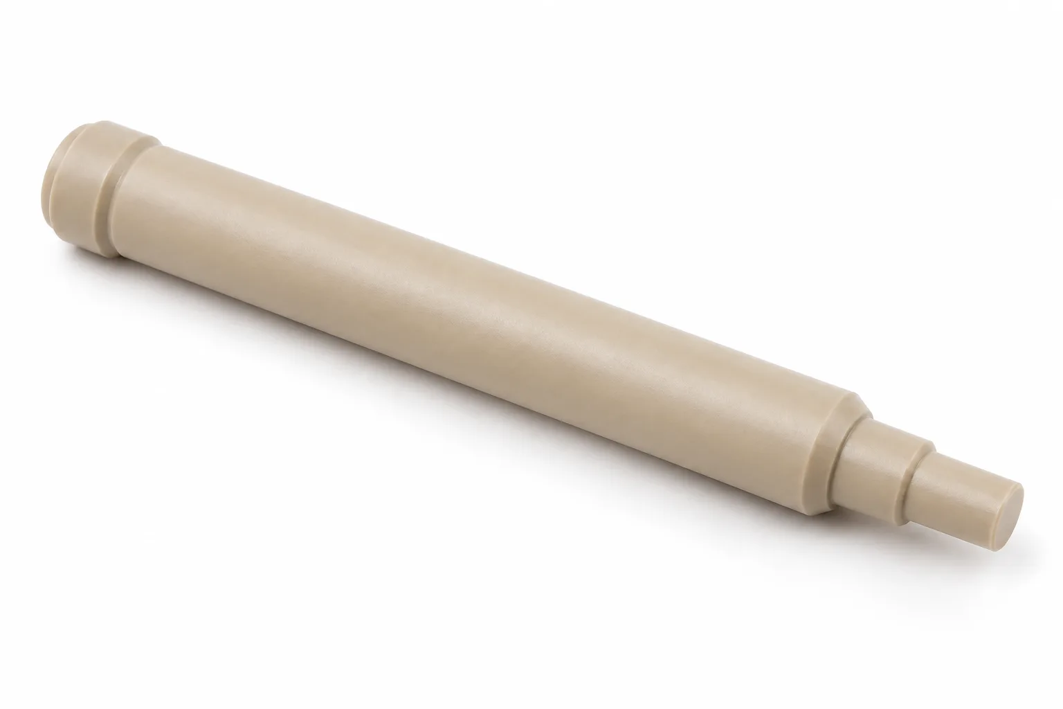
Straight PEEK Shafts
Simple cylindrical shafts for specialized mechanical assemblies. Support length and diameter must limit deflection; a finished shaft includes the specified end condition, not merely cut raw rod.
Explore this shaft geometry →
Custom Engineering Plastic Shafts
Precision CNC-machined PEEK shafts for industrial OEM applications. Custom diameters, stepped profiles, threads, grooves and material grades manufactured to your drawings.
A PEEK shaft manufacturer for finished, drawing-based components—not a standard PEEK rod stock listing.
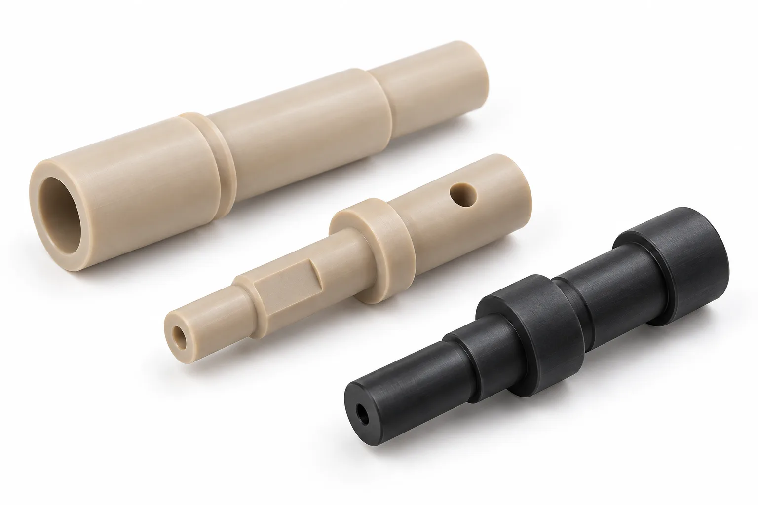
PEEK shafts are precision-machined cylindrical components manufactured from polyether ether ketone, a high-performance thermoplastic. They are used in mechanical assemblies requiring chemical resistance, electrical insulation, reduced weight or elevated-temperature performance. Custom PEEK shafts can incorporate stepped diameters, grooves, threads, flats and other features according to engineering drawings.
Swipe horizontally to read all columns.
| Property | Typical unfilled PEEK reference | Engineering qualification |
|---|---|---|
| Material family | Semi-crystalline thermoplastic | Polyether ether ketone; resin, stock form and processing history matter. |
| Density | Approximately 1.30 g/cm³ | Illustrative crystalline unfilled VICTREX 450G reference; not every filled grade. |
| Melting temperature | Approximately 343°C | VICTREX 450G reference; melting is not a shaft operating limit. |
| Glass transition temperature | Approximately 143°C | VICTREX 450G onset reference; stiffness and expansion behavior require review. |
| Continuous service temperature | Often cited around 250–260°C for suitable grades and conditions | A material reference, not an allowable temperature for every mechanically loaded shaft. |
| Electrical behavior | Unfilled PEEK is generally electrically insulating | Verify the actual grade; carbon and other additives can change conductivity. |
| Chemical resistance | Broad resistance, with important chemical-specific exceptions | Check chemical, concentration, temperature, duration and stress together. |
Values depend on resin grade, test method, stock form and service conditions. The continuous service temperature is not an allowable temperature for every mechanically loaded shaft. Reference properties are not acceptance values for an unidentified stock shape.
Density, melting temperature and glass-transition onset above refer to the crystalline unfilled VICTREX 450G manufacturer datasheet. The service-temperature context is also discussed in Ensinger's unfilled PEEK material information. These references explain material behavior; they do not establish Topshaft stock availability or a guaranteed shaft rating.
Swipe horizontally to read all columns.
| Question | Direct answer |
|---|---|
| What is supplied? | Custom finished shafts machined to drawings, not standard raw PEEK rods. |
| Typical features | Journals, steps, grooves, threads, flats, bores and specified end details. |
| What must be confirmed? | Exact grade, operating conditions, critical dimensions and inspection evidence. |
Choose the geometry around the assembly, then review its behavior in the selected polymer grade.
Simple cylindrical shafts for specialized mechanical assemblies. Support length and diameter must limit deflection; a finished shaft includes the specified end condition, not merely cut raw rod.
Explore this shaft geometry →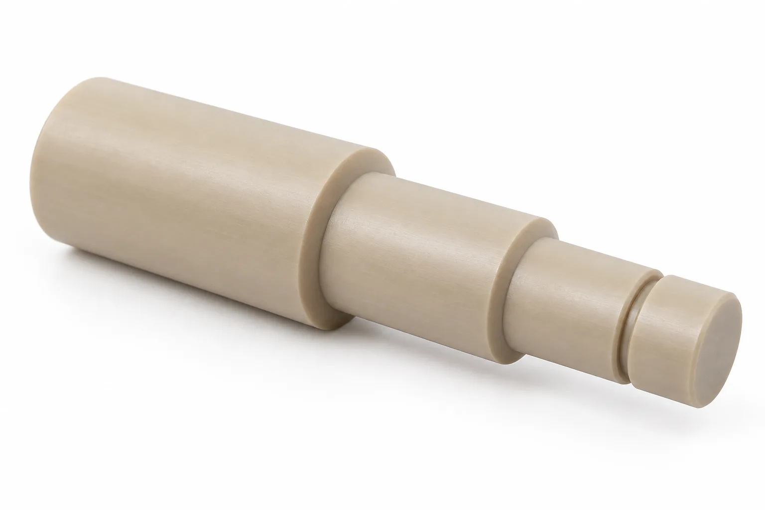
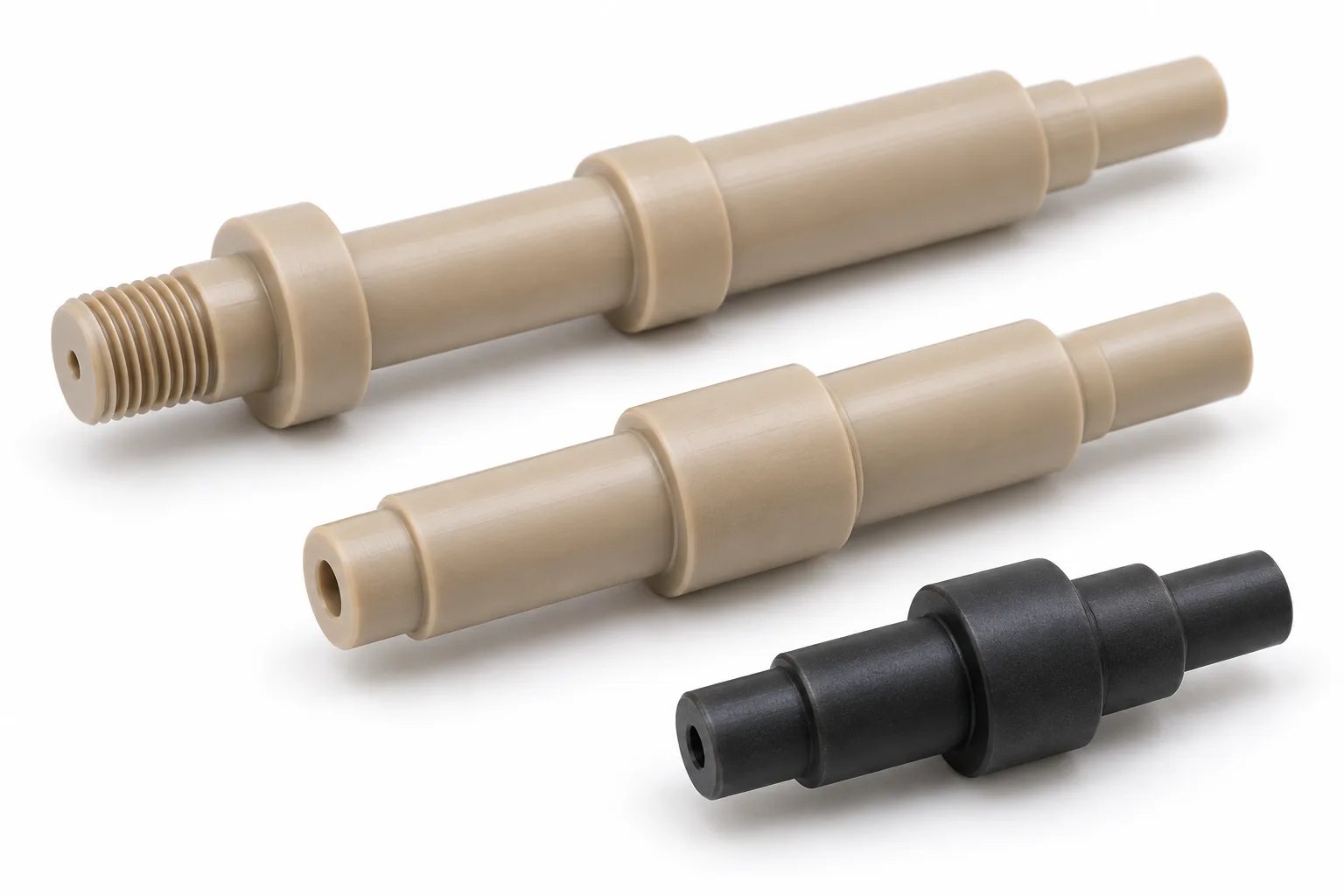
Multiple diameters locate bearings, spacers and mating components. Define shoulder positions, transition radii and fits, including thermal expansion and sustained contact pressure.
Explore this shaft geometry →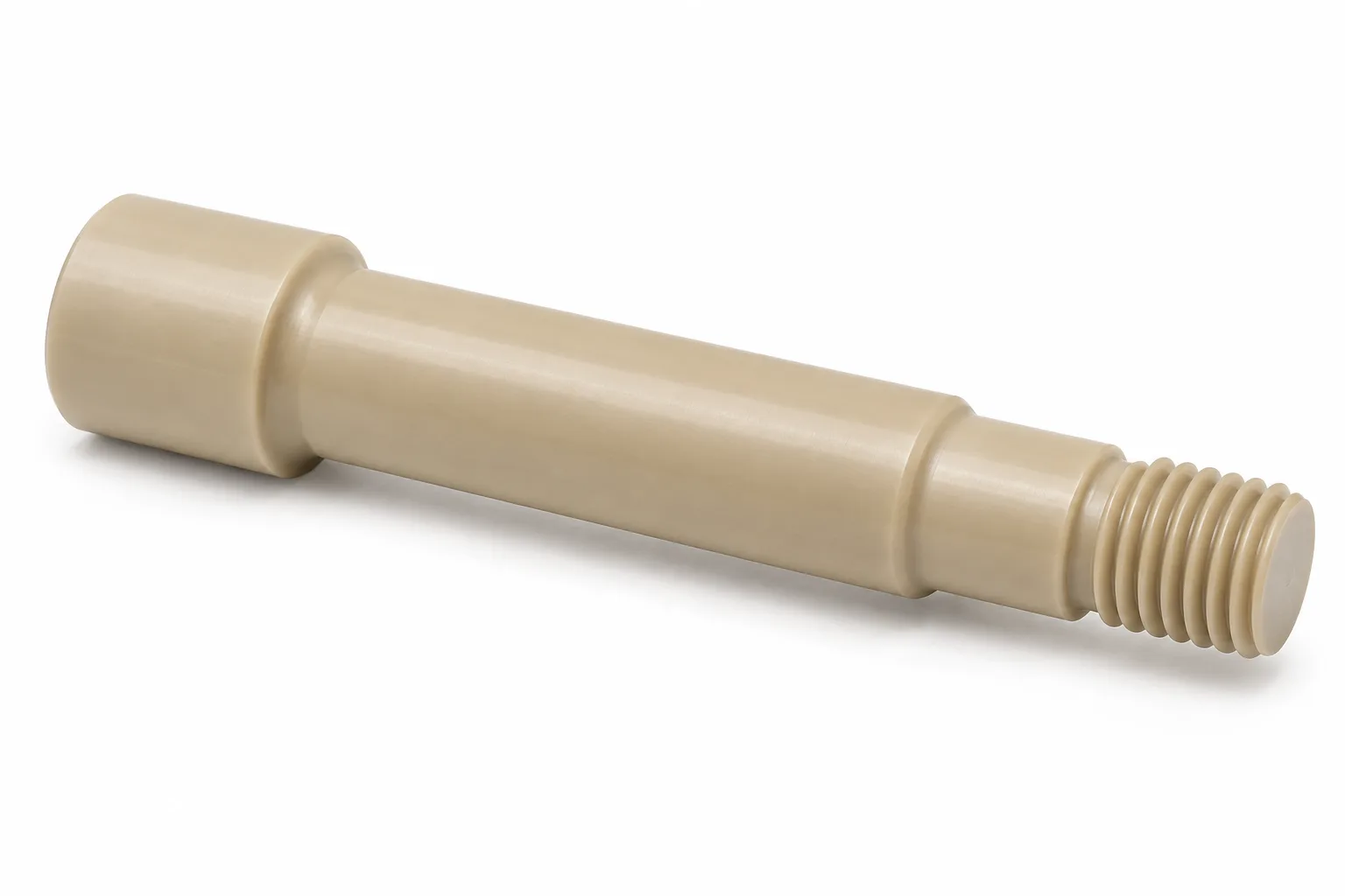
Custom threads for low-load adjustment and fastening. Review engagement, root geometry, assembly torque and creep; metal fastener torque assumptions should not be transferred unchanged.
Explore this shaft geometry →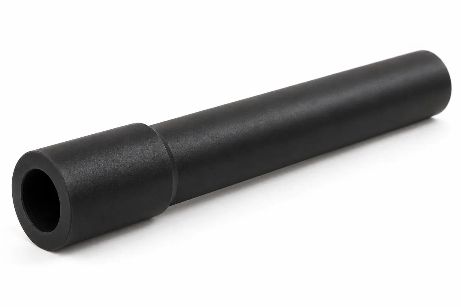
Internal bores allow weight reduction, routing or integration. Confirm bore access, wall thickness, clamping deformation and the required relationship between inside and outside surfaces.
Explore this shaft geometry →Additional geometries include grooved shafts, flatted shafts, miniature shafts and custom end features. Small features, sharp transitions and slender sections need their own machining and assembly review.
Specify the actual supplier designation, filler system and supplied condition. These families are considered for quotation, subject to sourcing and technical confirmation.
Swipe horizontally to read all columns.
| Grade family | Main characteristics | Suitable considerations |
|---|---|---|
| Virgin / Unfilled PEEK | Balanced toughness, chemical resistance and insulation | General precision components; verify electrical requirements and long-term deformation. |
| Glass-Filled PEEK | Higher stiffness and improved dimensional stability | Loaded components needing additional rigidity; review fiber orientation, toughness and mating-surface wear. |
| Carbon-Filled PEEK | Higher stiffness; improved thermal conductivity in some formulations | Specialized wear and structural applications; do not assume electrical insulation or equivalence between grades. |
| Bearing-Grade PEEK | Formulated for friction and wear performance | Sliding or bearing-contact components; match pressure, speed, lubrication and counterface. |
Reinforcement can change electrical properties, toughness, machining behavior and wear against mating parts. Not all carbon-filled grades are equivalent. A glass filled PEEK shaft also needs its own orientation, surface and counterface review.
Exact supplied grades and filler percentages have not been assigned here. Confirm them with the material datasheet during quotation rather than inferring them from a family name or image.
Swipe horizontally to read all columns.
| Material family | Filler percentage | Datasheet reference | Temperature suitability | Typical review use |
|---|---|---|---|---|
| Virgin / unfilled | Unfilled family; exact resin to confirm | Supplier datasheet and stock condition to agree | Check temperature, load duration and deformation | General precision or insulating components |
| Glass-filled | Percentage and fiber system to confirm | Named-grade datasheet required | Check directional properties and service loading | Additional rigidity and dimensional control |
| Carbon-filled | Percentage and formulation to confirm | Named-grade datasheet required | Check conductivity, toughness and thermal behavior | Structural or wear-related components |
| Bearing-grade | Additive blend to confirm | Named-grade wear and compatibility data required | Check contact pressure, speed and generated heat | Sliding interfaces and bearing contact |
Benefits are conditional: the grade and complete operating situation determine whether they support the application.
A candidate high temperature plastic shaft material where ordinary plastics are unsuitable. Select the grade for the actual stress, time and temperature; a headline service rating is not a design limit.
Useful in selected aggressive environments when compatibility is confirmed. Include cleaning agents and mixtures as well as the process fluid; resistance is not universal.
Lower density than common shaft metals can reduce component mass. A larger diameter or closer support may still be needed to meet stiffness and deflection requirements.
Suitable unfilled grades can isolate mechanical interfaces electrically. Carbon-filled or dissipative grades require their own electrical review rather than a blanket insulation claim.
Turning and milling can produce drawing-specific features without a dedicated molding tool. Heat control, sharp tooling and workholding remain important to final accuracy.
Selected bearing formulations may support sliding contact. Results depend on fillers, counterface, pressure, speed, lubrication, temperature and the permitted wear rate.
PEEK shaft machining coordinates cutting, clamping and inspection around a material that responds differently from metal.
Create external diameters and shoulders with sharp tooling, suitable support and controlled heat. Finish passes must account for elastic deflection rather than treating PEEK like steel.
Machine flats, slots and cross-features using clamping pressure that holds the component without distorting it. Datum transfer matters when features meet turned journals.
Produce internal features with suitable chip evacuation and heat control. Deep bores and thin walls need access, support and dimensional-stability review.
Define thread form, engagement and end relief. Review assembly load and creep, and inspect the interface in its specified final condition.
Remove loose edges without rounding functional geometry or leaving fibers and debris. Agree any specialized smoothing method for the named grade.
Check features after suitable stabilization, with measurement force, reference temperature and support matched to a compliant polymer component.
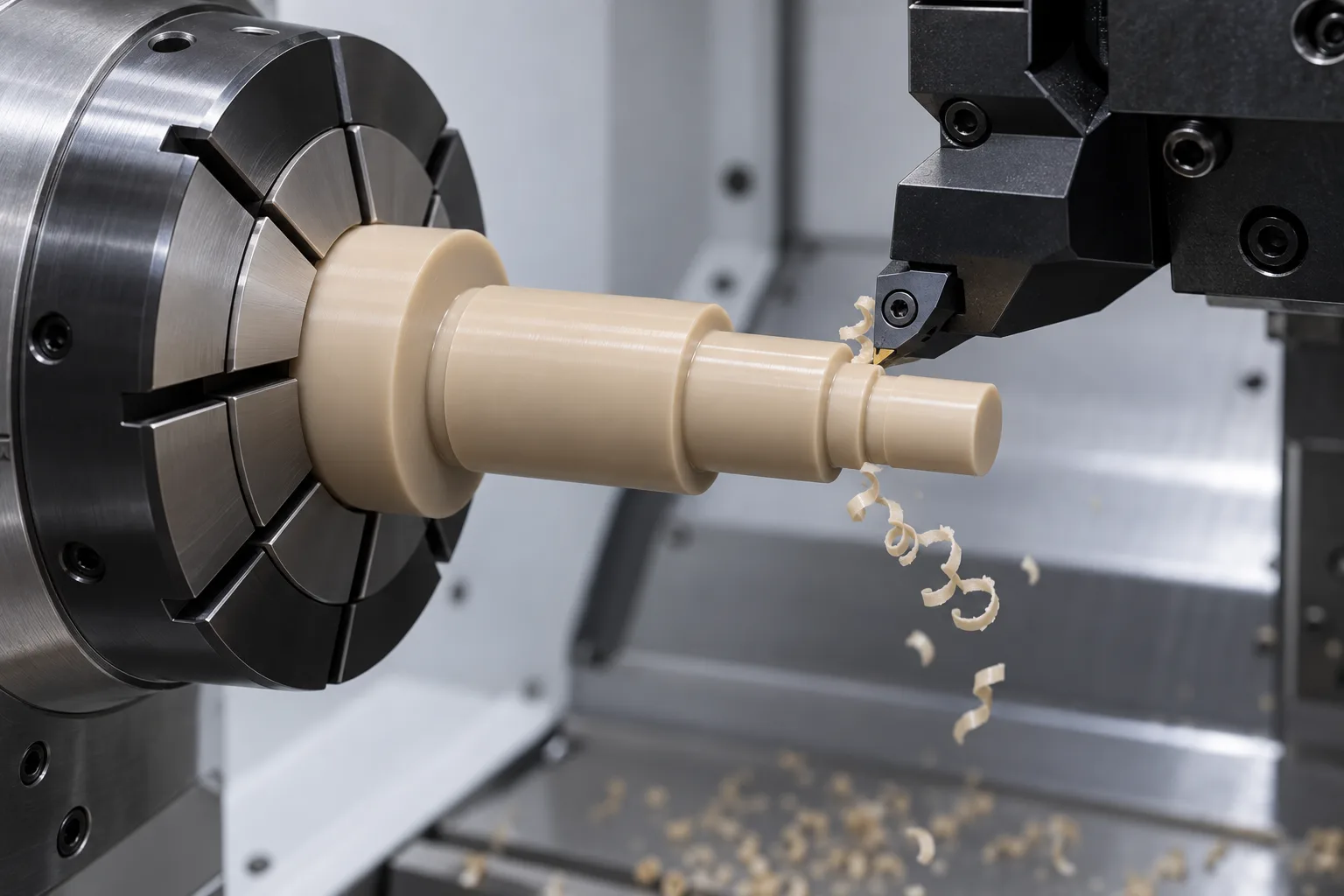
Internal stress, machining heat and clamping distortion can affect dimensions after cutting. Review stock preparation and any required stabilization with the actual route; do not assume one annealing schedule suits every grade.
Review CNC turning and features →A drawing-based capability review defines achievable features and inspection conditions before price and delivery are confirmed.
Swipe horizontally to read all columns.
| Specification | Project review scope |
|---|---|
| Material | Virgin, glass-filled, carbon-filled and other confirmed PEEK grades; exact supplier designation agreed. |
| Shaft diameter | Minimum and maximum are confirmed from the drawing, stock, workholding and available equipment; no unverified range is published. |
| Shaft length | Machining capacity is verified for the actual geometry, including support and slenderness requirements. |
| Dimensional tolerance | Quoted from diameter, length, geometry, grade, finishing and final inspection condition. |
| Surface roughness | Drawing-based Ra requirements on identified functional surfaces; inspection scope agreed. |
| Geometric tolerance | Straightness, runout, cylindricity and datum relationships as applicable; identify the actual characteristic rather than using concentricity as a catch-all. |
| Production volume | Prototype, small batch and repeat production, with the supported route and quantity confirmed. |
| Inspection | Calipers, micrometers, optical measurement and CMM where suitable for the feature, material and required uncertainty. |
Do not transfer a metal-shaft tolerance such as ±0.005 mm automatically to PEEK. Thermal expansion, moisture, internal stress, filler content and inspection temperature can materially affect achievable tolerances. Define final condition and acceptance method for critical dimensions.
Define tool-mark acceptance and final functional surfaces. A cosmetic appearance requirement should not replace a specified mating-surface texture.
Remove residual edges and loose material without changing journals, thread starts or locating shoulders. Polishing is considered only when purpose and grade compatibility are confirmed.
Coordinate secondary features with datum control, cleaning and dimensional inspection. Recheck sensitive dimensions after operations that can release stress or generate heat.
Anodizing, electroplating and passivation are not presented as normal PEEK finishing options. Specialized finishing requires confirmation of its purpose, grade compatibility and effect on final dimensions.
Potential application areas require engineering review; listing them is not evidence of delivered projects or sector approval.
Specialized shaft components where chemical compatibility, weight and operating load permit polymer construction. Review fluid, concentration, lubrication and running clearance.
Review related industry requirements →Precision components for selected chemically demanding or electrically insulating assemblies. Specify purity, particle, cleaning and documentation needs; suitability is not automatic.
Review related industry requirements →Custom components for instrument mechanisms, subject to application-specific material and regulatory requirements. Generic PEEK is not evidence of implant or patient-contact qualification.
Review related industry requirements →Lightweight or insulating shafts for selected low-load motion and positioning mechanisms. Review bearing support, deflection, wear and repeated assembly loads.
Review related industry requirements →Electrical equipment may need defined insulation or dissipative behavior. Aerospace-related systems may require specified material provenance, qualification and release records. Neither requirement is demonstrated by choosing PEEK alone.
Swipe horizontally to read all columns.
| Material | Main advantage | Main limitation |
|---|---|---|
| PEEK | Thermal and chemical performance with low weight | Higher cost and lower stiffness than metals; creep and temperature-dependent behavior require review. |
| Stainless Steel | Strength, stiffness and durability | Higher weight; grade and environment still determine corrosion suitability. |
| Aluminum | Low weight and good machinability | Temperature capability and chemical compatibility may be limiting in particular environments. |
| POM / Delrin | Low friction and cost-effective machining | Lower high-temperature capability than PEEK; grade and exposure still matter. |
Choose PEEK instead of metal when the assembly benefits from chemical or thermal performance, low weight or suitable electrical behavior, and its loads, stiffness and long-term deformation are acceptable. A PEEK vs stainless steel shaft decision must include geometry and support, not simply replace one material name on the drawing.
PEEK is generally not the default for maximum torque transmission, heavy loading or long unsupported rotating shafts. Review deflection, creep, fatigue, thermal clearance and contact conditions; redesign or a metal shaft may be necessary.
The inspection plan should reflect polymer behavior as well as the drawing limits.
Confirm the agreed supplier grade, stock identification, condition and required traceability documents. Color alone does not establish filler content or electrical behavior.
Check diameters, lengths, shoulders, bores and thread geometry against the released drawing using a suitable measurement method.
Use the specified datum setup and support. Distinguish actual part error from deflection introduced by fixtures or the measuring instrument.
Review edges, machining damage, residual fibers and surface condition. Agree first-article or final reports, sampling, acceptance and shipment identification.
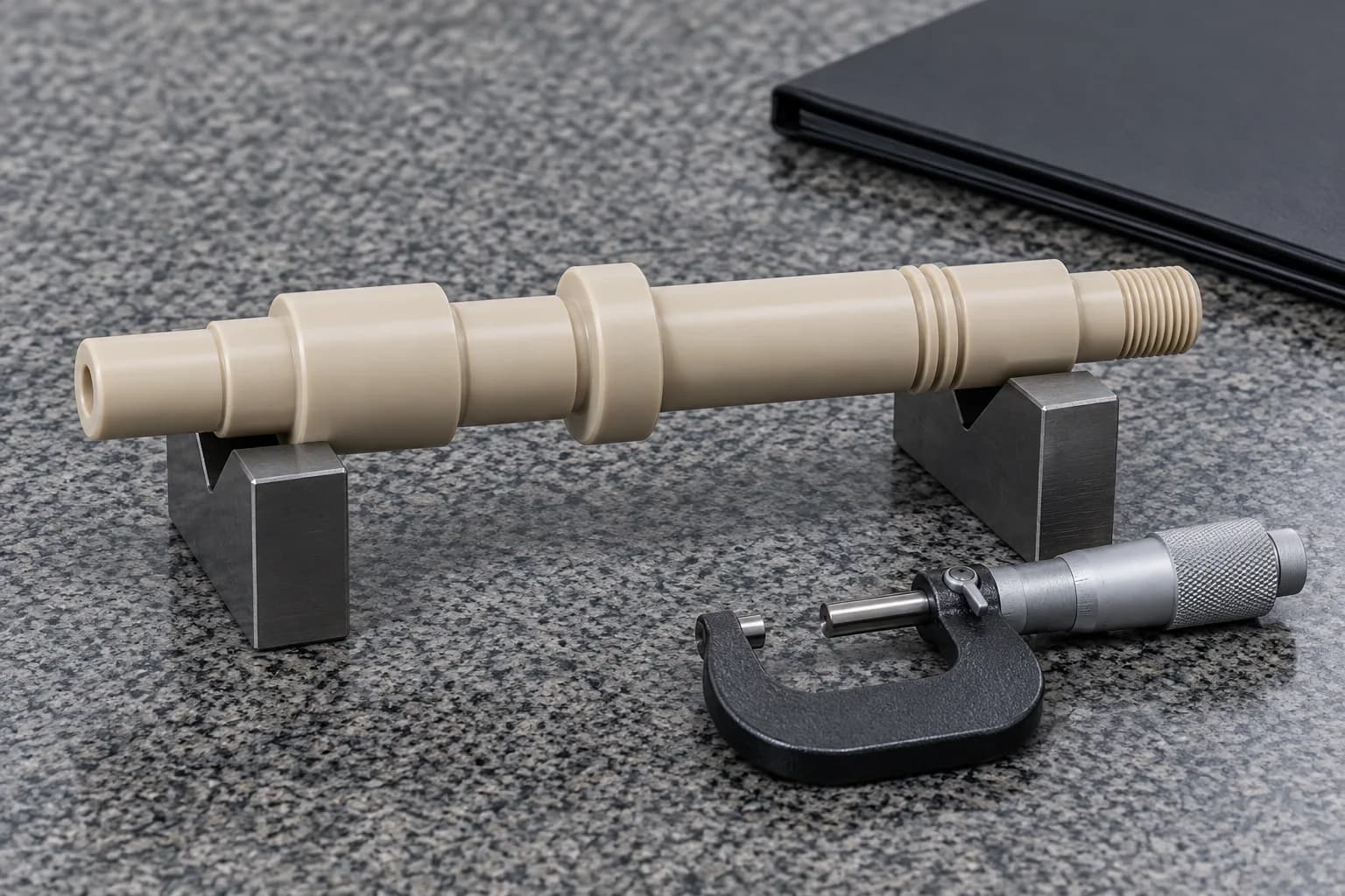
Temperature and measurement force matter. High contact or clamping force can distort the part and the result. Agree stabilization, reference temperature, fixture support and the decision rule near a limit; compare methods before attributing a disagreement to the material.
Shaft quality inspection →Shaft geometry manufactured to customer specifications, with the drawing revision and critical interfaces identified before production.
Support in comparing PEEK families and alternative materials; confirm the exact grade and unresolved operating requirements.
Turning, milling and secondary features according to confirmed capabilities, with polymer-specific process and workholding review.
Inspection and traceability documentation according to agreed project requirements, not an unsupported blanket certification claim.
TOPSHAFT is the precision shaft manufacturing division of Dongguan Tops Precision Manufacture Co., Ltd., operating alongside Topsbest Precision for shaft-focused OEM projects. Learn about Topshaft and agree the project evidence you require.
Custom shaft manufacturing →A PEEK shaft is a finished cylindrical component made from polyether ether ketone. It can include journals, steps, grooves, threads or bores for an engineered assembly; a raw PEEK rod is not automatically a finished shaft.
Sometimes, but not as a direct material swap. Compare stiffness, torque, fatigue, creep, temperature, fit and chemical exposure. A redesign or different bearing support may be needed, and a metal shaft may remain the better choice.
There is no single maximum for every shaft. Around 250–260°C is often cited for suitable material grades and conditions, but allowable service depends on load, time, environment and acceptable deformation. Neither melting temperature nor an electrical temperature rating establishes a mechanical shaft limit.
Yes, where the geometry, grade and agreed inspection conditions support them. Thermal expansion, internal stress, moisture and measurement force affect precision PEEK shafts. Critical tolerances need drawing-specific review rather than a universal metal-shaft tolerance promise.
Virgin PEEK is unfilled, while carbon-filled grades contain a specified carbon reinforcement or additive system. Filling can change stiffness, heat transfer, toughness, wear and conductivity; a carbon fiber reinforced PEEK shaft is not automatically electrically insulating.
They can be suitable for selected rotating assemblies. Check torque, speed, support span, deflection, balance, creep and bearing contact. High-torque, heavily loaded or long unsupported rotating designs should not default to PEEK.
Topshaft can review threaded and hollow PEEK shaft projects from drawings. Engagement, wall thickness, bore access, clamping and the exact material grade determine the feasible route; final manufacturing scope is confirmed during quotation.
Send the drawing or CAD model, exact material grade if known, quantity, critical tolerances, surface finish, operating temperature, loads, chemical exposure and inspection requirements. A PEEK shaft supplier also needs the delivery target and any traceability or application-specific documentation.
Drawing-Based Manufacturing Review
Send your drawing, material requirements, quantity and operating conditions. Engineering drawings and material requirements are reviewed before confirming manufacturability, price and lead time.