
How To Specify A Shaft Retaining Ring Groove: Dimensions, Axial Location And Inspection
A shaft retaining ring groove needs more than a nominal diameter. You must connect the ring specification, groove geometry and retained assembly. This guide explains what to put on your drawing, what to inspect, and what to clarify before requesting custom shafts.
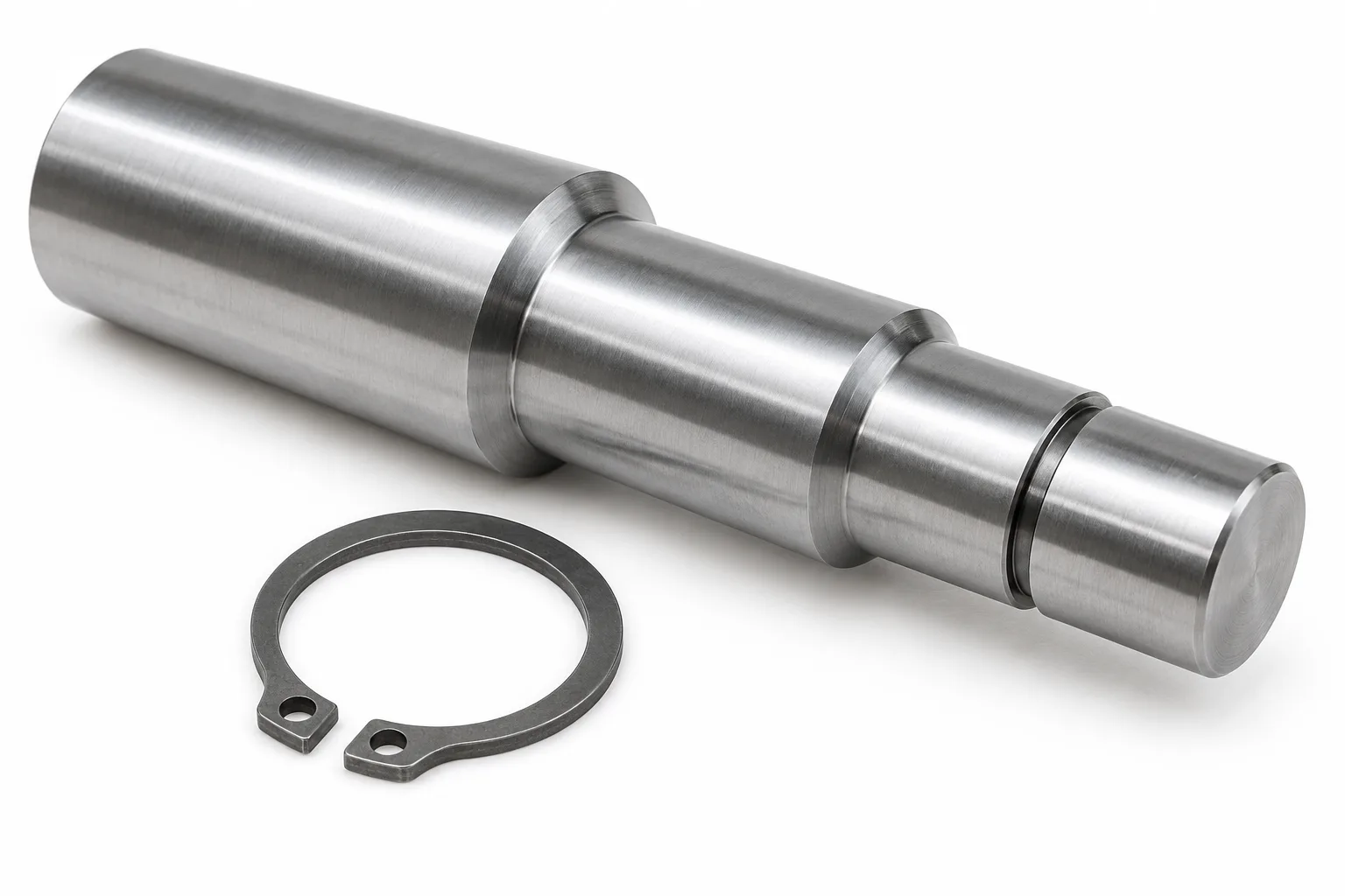
Illustrative product visual. This is not a customer drawing or evidence of a manufactured TOPSHAFT part.
Select The Retaining Ring Before Defining The Groove
Your groove must match the selected retaining ring and its installation method.
Start with the ring manufacturer, series, size and material. Record the applicable standard when your design uses one. A shaft diameter alone does not identify the correct groove.
An external circlip, spiral ring and radially installed ring may require different geometry. Their installation access also differs. Do not assume interchangeable grooves because two rings fit the same nominal shaft.
An external retaining ring normally engages a shaft groove. An internal ring normally engages a bore groove. Keep these applications separate when selecting catalog dimensions.
Specify the complete part number or a controlled equivalent. If alternatives are permitted, identify the properties requiring engineering approval. These may include thickness, load rating, material, coating and installation method.
The Rotor Clip retaining ring FAQ explains the distinction between ring families and installation approaches. Use the selected product's current specification for actual dimensions.
For your purchasing team, ring identity is configuration control. An undocumented substitution can change assembly behavior even when the nominal shaft diameter remains unchanged.
Define The Complete Shaft Groove Geometry
Your drawing should define groove diameter, width, position, corner geometry and the required finished condition.
Use the ring supplier's recommended groove dimensions as your design starting point. Then review the surrounding shaft and assembly. The final drawing must resolve conflicts rather than leave the machinist to choose.
| Drawing Requirement | What You Need To Define | Why It Matters |
|---|---|---|
| Groove bottom diameter | Finished diameter and tolerance | Controls ring engagement |
| Groove width | Finished width and tolerance | Controls seating and available axial movement |
| Axial location | Distance from a functional reference | Positions the retained component |
| Root geometry | Permitted radius or specified profile | Prevents incompatible ring seating |
| Groove edges | Controlled deburring and edge condition | Avoids assembly damage without removing support |
| End margin | Remaining material beyond the groove | Supports the retaining feature |
| Final condition | Before or after specified treatments | Makes acceptance requirements clear |
Avoid dimensioning both groove depth and bottom diameter as independent controls without checking consistency. They describe related geometry. Conflicting tolerances can produce an impossible requirement.
If one dimension is informational, identify it accordingly using your drawing convention. Do not ask production to decide which conflicting dimension takes priority.
Large unspecified corner radii can prevent proper seating. Conversely, demanding an unrealistically sharp corner creates manufacturing and inspection problems. Resolve the permissible geometry with the ring supplier and shaft manufacturer.
Call out edge treatment carefully. A generic instruction to break all edges may conflict with the groove's load-bearing wall. Explicit local requirements should remove that ambiguity.
For surrounding turned features, see CNC Turning & Features. Groove requirements must work with adjacent shoulders, threads and journals.
Locate The Groove From The Functional Assembly
Your groove position should follow the assembly's locating surfaces, not an arbitrary shaft end.
Identify the face that actually positions the bearing, spacer or gear. Then determine which groove wall receives the axial reaction. That relationship should drive your dimensioning scheme.
Dimensioning from a remote end may introduce unnecessary tolerance accumulation. It can still be appropriate when that end is functional. The choice depends on the actual locating arrangement.
Distinguish a groove centerline dimension from a load-bearing-wall dimension. Either can be defined clearly. Problems arise when the drawing leaves the intended relationship uncertain.
Consider every component between the shoulder and ring. Include bearing width, spacer length, washer thickness and ring thickness where relevant. Also include the specified groove width and location tolerances.
Check both extremes of the stack. One extreme may prevent complete ring seating. The other may create excessive end play. Nominal dimensions alone will not reveal either problem.
Do not treat ordinary retaining rings as automatic preload devices. Some specialized designs address axial clearance, but their function requires deliberate selection. Define preload separately when your assembly needs it.
Coordinate the groove with your bearing journal specifications. A correct journal fit cannot compensate for an incorrect axial locating stack.
Review Load, Speed And The Remaining Shaft Section
You must evaluate the ring, groove and shaft together under the intended operating conditions.
A stronger ring does not automatically strengthen a weak groove. The retained component's contact geometry also matters. Identify the load path before comparing catalog ratings.
Smalley describes two relevant limits: ring shear and groove deformation. The lower allowable limit governs its retaining-ring assembly assessment. Its published formulas exclude dynamic and eccentric loading. Those conditions need appropriate engineering allowance and testing. See Smalley's load-capacity guidance.
This principle does not provide a universal rating for every circlip. Apply the chosen supplier's methods to the actual product. Do not copy a safety factor from another ring family without review.
Communicate steady axial load, shock load, load direction and operating speed. Include whether the loading reverses. Temperature and corrosion conditions may also affect selection.
For rotating external rings, check the supplier's speed guidance. Retention behavior depends on the design and installation. Do not infer a safe speed from appearance alone.
Separately review the shaft's reduced section at the groove. Torsion, bending and fatigue remain shaft-design concerns. A retaining-ring load rating does not certify the whole shaft.
Pay attention when the groove sits near a shaft end. The remaining material must support the selected loading arrangement. Use product-specific guidance rather than an unsupported universal end-distance rule.
Coordinate Material, Heat Treatment And Coating
Your groove dimensions must apply to the material and surface condition accepted at final inspection.
State the shaft material specification and required condition. A material name without its condition may leave important strength assumptions unresolved. Confirm whether your calculations use the final material properties.
Heat treatment can change dimensions and affect finishing choices. Decide whether the groove is machined before or after treatment. That decision should follow the material, geometry and achievable final requirements.
If the groove is within a hardened zone, define the treatment coverage clearly. Do not assume the groove receives identical properties to an adjacent journal. Discuss local treatment boundaries when these affect function.
For further drawing guidance, see shaft heat-treatment specifications. Treat hardness, treatment depth and finished geometry as related requirements.
Coating can alter groove clearance and engagement. State whether dimensional acceptance applies after coating. Identify masked surfaces if your design requires them.
Also review ring and shaft corrosion compatibility. Protective treatment should not be selected solely for appearance. Check the application's environment and the selected ring supplier's recommendations.
Do not resolve a dimensional problem by polishing the groove indiscriminately. Uncontrolled material removal can change the load-bearing geometry. Any rework must preserve the approved drawing requirements.
Plan Machining And Controlled Deburring
Your machining plan must preserve the groove's functional geometry while removing harmful burrs.
A narrow groove can demand a dedicated grooving tool and careful tool control. Adjacent shoulders may restrict access. Long, slender shafts may require additional support during machining.
Discuss these conditions during quotation. A groove near a large shoulder may be more difficult than an isolated groove. Inspection access may also become restricted.
Avoid unnecessary tight tolerances on every dimension. Identify the controls that protect engagement and assembly position. Requirements should follow function, not a general preference for smaller numbers.
Burrs can interfere with ring seating or damage components during installation. Specify an acceptable edge condition and inspection approach. Keep that instruction consistent with the required groove-wall support.
Review what slides over the groove during assembly. A bearing, seal or spacer may contact its edges. Plan protection and assembly sequence rather than relying only on visual deburring.
Do not assume that removing visible burrs proves the groove is acceptable. Width, diameter and wall geometry still require verification. Cleaning must also remove loose chips before assembly.
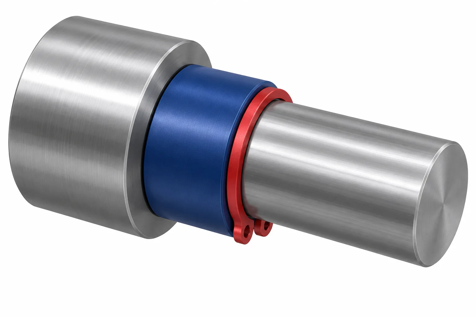
Illustrative assembly geometry only. Ring selection, dimensions and operating limits require product-specific engineering review.
Inspect Dimensions And Confirm Seating Separately
Dimensional inspection and assembly checks answer different questions, so you need both when function requires them.
First, define what each measurement must establish. A general-purpose caliper may not reach the groove bottom correctly. A reading across unsuitable contact points can look plausible but measure the wrong feature.
Choose instruments with suitable contact geometry and access. Depending on the feature, options include appropriate groove gauges, optical measurement or validated coordinate measurement. The method must support the specified tolerance.
Measure groove width and axial location from the defined references. Review whether corner radii or edge breaks influence the reading. Document the measurement method for critical features.
Inspect the groove around its circumference where your acceptance plan requires it. A single accessible section may not reveal local burrs or incomplete machining. Define sampling rather than leaving it implicit.
Then confirm installation using the approved ring and assembly procedure. Check that the ring seats fully and remains undamaged. Inspect the intended contact with the retained component.
An assembly check is not automatically a dimensional gauge. A ring may install despite a feature being outside drawing limits. Likewise, an installation difficulty may arise from the wrong ring or tooling.
Agree the required reports before production. The Inspection & Quality page explains drawing-based inspection planning. Any particular instrument or report should be confirmed for your order.
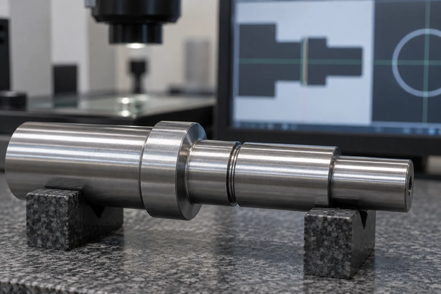
Generic inspection illustration. This image does not identify TOPSHAFT equipment or an actual inspection result.
Prepare A Clear Drawing And RFQ Package
Your quotation package should identify the ring interface and the shaft requirements without forcing supplier assumptions.
Send the controlled 2D drawing, available CAD model and drawing revision. Include the selected ring specification. Clearly distinguish customer-supplied rings from items requiring separate sourcing.
Use this checklist before requesting pricing:
- Shaft material specification and final condition.
- Ring manufacturer, part number and approved alternatives.
- Groove diameter, width, axial position and corner limits.
- Functional locating face and relevant assembly stack.
- Heat treatment, coating and masking requirements.
- Critical characteristics and agreed inspection records.
- Prototype quantity, production quantity and expected repeat demand.
- Assembly access and any customer-defined installation constraints.
Communicate operating requirements when asking for engineering review. Manufacturing to a drawing is not the same as approving its load capacity. Define responsibility for design validation explicitly.
Cost depends on access, tool requirements, material condition, tolerance and inspection effort. A difficult local feature can influence the complete route. There is no reliable universal surcharge per groove.
Use the precision shaft RFQ checklist to organize the wider package. Clarifying interfaces early helps suppliers quote comparable requirements.
Know When Another Retention Method Needs Review
A retaining-ring groove is not automatically the best solution for every shaft assembly.
Review alternatives when the remaining shaft section becomes unacceptable. Limited installation access or demanding axial positioning may also justify another route. Dynamic loading requires particular care.
Possible alternatives include shoulders with threaded retention, clamping arrangements or other engineered locating methods. Each introduces its own space, machining and assembly requirements. Compare the complete arrangement rather than only fastener cost.
Changing retention methods is an engineering decision. Do not substitute one during production without approval. Update the shaft drawing, assembly documentation and purchasing requirements together.
Frequently Asked Questions
Can You Specify The Groove From Shaft Diameter Alone?
No. You also need the selected ring specification and its recommended groove geometry. Assembly and loading requirements complete the review.
Should The Groove Width Equal The Ring Thickness?
Do not assume equality. Use the selected ring's specified groove width and tolerances. Check the resulting axial clearance separately.
Does A Ring That Fits Prove The Groove Is Correct?
No. Installation verifies only part of the interface. Diameter, width, position and corner geometry still require drawing-based acceptance.
Can You Use A Standard Edge-Break Note Everywhere?
Only when it remains compatible with the local groove requirements. Define exceptions where the load-bearing geometry needs specific control.
Should Groove Dimensions Be Checked After Coating?
Yes, when your drawing specifies finished coated dimensions. Otherwise, explicitly define the acceptance stage and required coating control.
Can A Retaining Ring Set Bearing Preload?
Do not assume a standard ring provides controlled preload. Select and validate the complete arrangement when preload is required.
Are Catalog Load Ratings Enough For Shock Loading?
Not automatically. Check the rating's assumptions and obtain application-specific guidance. Dynamic conditions may require engineering assessment and testing.
What Should You Send For A Custom Shaft Quote?
Send the shaft drawing, selected ring specification, material condition, quantities and inspection requirements. Include assembly constraints requiring review.
Request A Drawing-Based Shaft Review
Send your shaft drawing, ring specification, assembly requirements and quantities through Contact Us. Ask TOPSHAFT to confirm manufacturing feasibility and inspection scope. Keep ring selection and application load validation within the agreed engineering responsibilities.