
Shaft And Bearing Interference-Fit Assembly: Pressing, Heating And Acceptance — An OEM Checklist
A successful shaft and bearing assembly needs more than matching nominal diameters. Define the fit, mounting method, force path, cleanliness and acceptance checks before production. This guide helps OEM teams connect a shaft drawing with a controlled assembly plan, without assuming one temperature or pressing force suits every bearing.
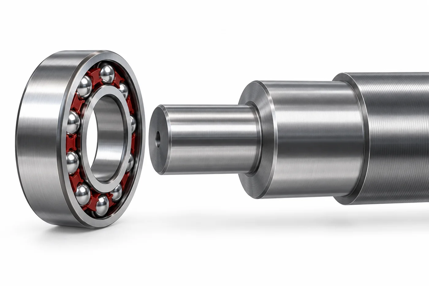
*Technical illustration, not a TOPSHAFT production photograph or an approved assembly instruction.*
Separate Fit Selection From Mounting Instructions
The drawing defines the required interface; the assembly instruction explains how to achieve it without unacceptable damage.
A tolerance designation does not tell an operator which tooling to use. Nor does it establish heating limits, component orientation or final inspection requirements.
First confirm the actual bearing designation and supplier information. Bearings with different internal arrangements or supplied conditions can need different mounting procedures. Do not transfer instructions merely because two bearings share a nominal bore.
Your engineering team should approve the fit for the application. Load direction, operating temperature and bearing arrangement can influence that decision. This article does not prescribe a universal fit class.
NSK's mounting guidance distinguishes preparation, mounting, inspection and running tests. Consult the bearing maker's product-specific instructions rather than treating this procurement checklist as a workshop procedure.
Use the bearing journal specification guide for drawing requirements. Keep this article focused on assembling the approved components and verifying the result.
Define responsibility as well. A shaft supplier making an individual component does not automatically control bearing procurement or final assembly. Put the agreed scope into the order.
Check The Components Before Choosing The Process
Verify the actual components and their condition before committing them to assembly.
Check shaft identity, drawing revision and bearing designation against the approved bill of materials. Confirm the relevant journal, shoulder and lead-in requirements. Look for handling damage, contamination and unintended coating on the seat.
Confirm the dimensional inspection method and measurement conditions. A reading from a recently heated component may not represent its size under the specified inspection conditions. Record any temperature requirements in the inspection plan.
Review roundness, surface condition and shoulder geometry where specified. A nominal diameter reading alone does not prove every interface requirement. Follow the approved drawing rather than creating new tolerances at the assembly station.
Do not polish a shaft seat informally to make a bearing slide on. That changes the approved interface and can hide the original cause of difficulty.
Keep bearing protection intact until the planned preparation stage. Follow the bearing manufacturer's handling and cleaning instructions, especially for sealed or prelubricated products.
Select Pressing Or Thermal Mounting Deliberately
Choose the mounting method using the bearing manufacturer's guidance and the approved assembly design.
Mechanical mounting uses controlled force and suitable tooling. Thermal mounting creates temporary dimensional clearance through a controlled temperature difference. The appropriate choice depends on the component, fit and assembly arrangement.
| Planning Question | Mechanical Mounting | Thermal Mounting |
|---|---|---|
| How is the fit overcome? | Controlled axial force through suitable tooling | Temporary expansion or contraction under an approved procedure |
| What must be prepared? | Support, alignment, tooling contact and process limits | Heating equipment, temperature control, handling and placement sequence |
| What can go wrong? | Misalignment, unsuitable load path or uncontrolled force | Excess temperature, uneven heating or delayed placement |
| What must be confirmed? | Part-specific method and acceptance evidence | Component-specific thermal limits and final seating checks |
Neither column is a complete operating procedure. Specialist mounting methods may be appropriate for particular bearing types. Do not treat every shaft and bearing arrangement as a simple straight-bore press fit.
Avoid selecting a method solely because equipment is available. Confirm that the tooling and process suit the approved parts. Include dismantling and maintenance access when the design requires future replacement.
Control The Load Path During Mechanical Mounting
Mounting loads should follow the appropriate fitted-ring load path rather than pass unnecessarily through rolling contacts.
For a bearing inner ring fitted onto a shaft, review tooling that acts on the intended inner-ring face. Keep the support and pressing direction aligned with the shaft axis. The actual arrangement must follow the bearing manufacturer's instructions.
If both rings are being fitted in one operation, the tooling needs a corresponding review. Do not assume tooling suitable for a shaft-only fit is suitable for simultaneous housing installation.
Check tool clearances against cages, seals, shields and adjacent features. A sleeve can appear aligned while touching an unintended component. Review its contact face and access before the first assembly.
Establish process limits using an approved method. Force depends on fit, geometry, surface condition and other assembly variables. A universal force copied from an unrelated part is not a reliable acceptance rule.
An unexpected force increase should trigger a controlled stop and investigation. Do not compensate by increasing machine capacity or striking the assembly. Preserve the parts and process evidence for review.
Define Thermal Limits Without Guessing
Thermal mounting requires component-specific temperature limits and a planned handling sequence.
Consult the bearing manufacturer for allowable heating, equipment and handling requirements. Seals, lubrication and bearing construction can constrain the process. Do not copy one temperature setting across a mixed bearing inventory.
Heating should be controlled rather than improvised. Do not use an open flame as a substitute for a suitable mounting process. Temperature must be measured through an appropriate, agreed arrangement.
Plan the transfer from heating to placement before starting. Have the correct shaft orientation, tooling and safe handling arrangements ready. An expanding bearing does not provide unlimited placement time.
SKF's vertical-mounting discussion explains why the heating and cooling sequence deserves attention. Your approved plan must address the actual bearing arrangement.
Confirm seating and any required retention during cooling under the approved instruction. A bearing appearing positioned while hot may need further verification after stabilization.
Cooling a component also needs review. Condensation, cleanliness and compatibility with surrounding parts can matter. This guide does not prescribe a shaft-freezing process or a universal temperature difference.
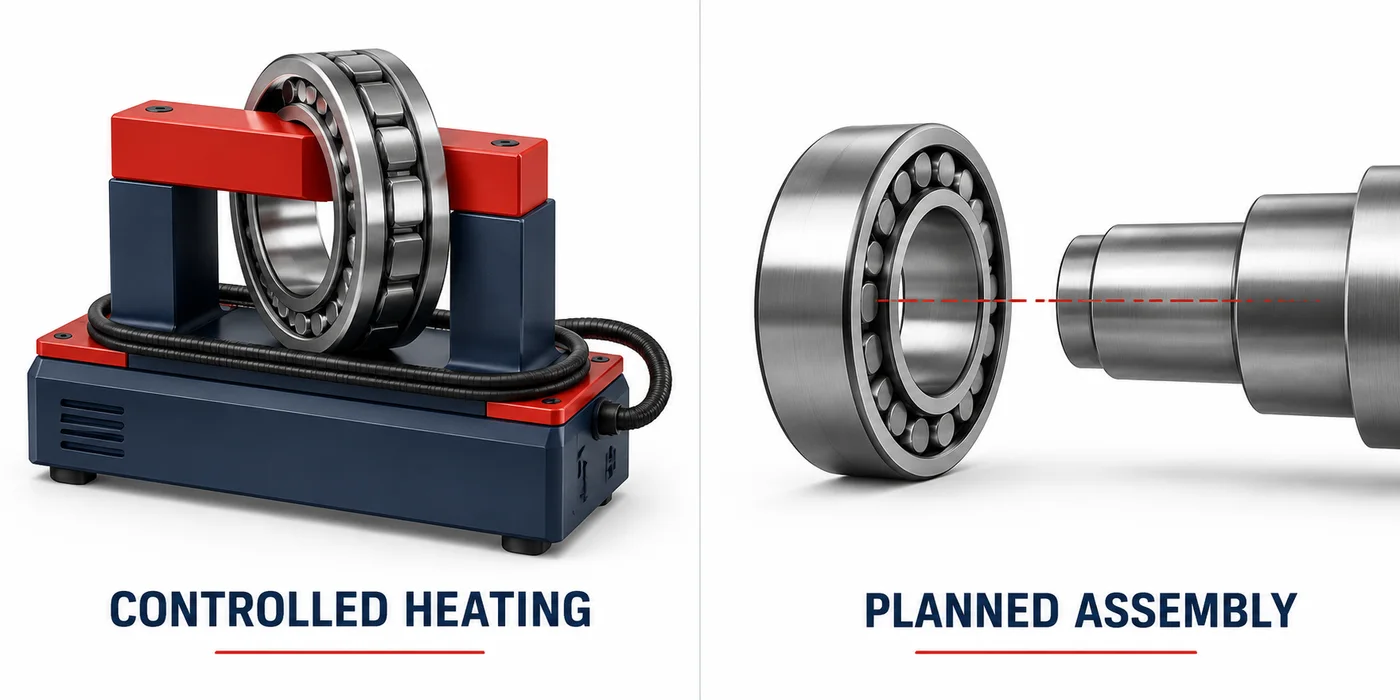
*Concept illustration only. No temperature, equipment setting or validated process is specified.*
Prepare Clean Surfaces And Compatible Protection
Assembly preparation should remove harmful contamination without disregarding the bearing's supplied condition.
Inspect the journal and shoulder for loose debris, burrs and packaging residue. Check that protection caps and labels have been removed from the required interfaces. Do not transfer contaminants from dirty gloves or benches.
Follow the bearing supplier's preparation requirements. Do not wash a sealed, grease-filled bearing simply because the shaft has a cleaning step. Cleaning practices must suit the actual product and lubricant arrangement.
Agree any approved mounting medium or lubricant. Do not assume an oil suitable for storage protection is automatically suitable for the fitted interface. Likewise, do not add an adhesive unless the design authorizes it.
Use the shaft cleanliness requirements guide to define critical areas and acceptance. Coordinate protection with the intended assembly process rather than adding a generic “clean” note.
If a coating or corrosion inhibitor is present, confirm its permitted location and removal requirements. Inspection should reflect the final functional surface condition required by the drawing.
Confirm Shoulder Contact And Axial Position
Verify the specified final position rather than judging the assembly by appearance alone.
Identify the drawing reference used for axial location. Check the bearing orientation and the shoulder or spacer arrangement. Define the inspection method before assembly, especially where access will become restricted.
A gap may result from geometry interference rather than insufficient force. Review shoulder fillets, bearing corner clearance and any specified relief. Do not force a ring over an incompatible transition.
Refer to the shaft shoulder and fillet guide when reviewing interface geometry. Do not change a radius or relief at the assembly station without engineering approval.
Confirm specified retaining parts and their installation condition. A locknut, spacer or retaining ring does not automatically establish the correct bearing preload. Use the approved arrangement and adjustment instructions.
For an assembly containing multiple bearings, confirm which component locates the shaft axially. Do not unintentionally constrain an arrangement intended to accommodate movement.
Set Acceptance Checks Before The First Assembly
Your acceptance plan should state what will be checked, when and against which requirement.
Dimensional conformity of the individual shaft does not establish assembled performance. Select checks appropriate to the actual machine and bearing arrangement.
Possible checks include axial position, required clearances, rotation and specified assembled runout. Define the measurement setup and reference features. Do not introduce a generic runout limit unrelated to the drawing.
Rotation checks must account for seals, lubricant and the assembly state. Free spinning by hand is not a universal pass criterion. Equally, unexpectedly restricted movement requires investigation, not assumption.
Where the machine's approved procedure includes a running test, define operating conditions and monitoring. Use product-specific limits for temperature, noise or vibration. Do not commission equipment solely from a successful hand-rotation check.
Record acceptance after the specified thermal stabilization where applicable. A check performed during cooling may not represent the final assembly condition.
Keep Records That Support Troubleshooting
Connect assembly results with the actual shaft, bearing and process revision.
Agree the necessary records during planning. Depending on your project, record:
- Shaft part number, drawing revision and lot or serial identifier.
- Bearing designation and traceability reference required by the contract.
- Assembly instruction and tooling revision.
- Required dimensional and surface checks before mounting.
- Recorded process parameters specified by the approved procedure.
- Final position and other agreed acceptance results.
- Deviations, rework decisions and responsible approvals.
Do not collect measurements without explaining their role. Distinguish process-monitoring information from formal acceptance criteria. Both may be useful, but they answer different questions.
For new programs, link the record to your first article inspection plan. An approved first assembly should establish the repeatable process, not replace required production checks.
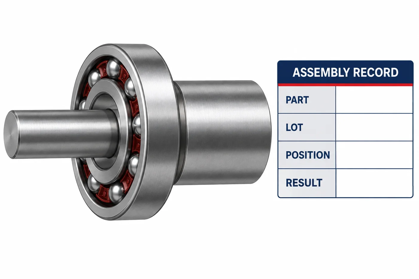
*Illustrative documentation relationship, not a real inspection result or customer assembly.*
Investigate Difficult Assembly Before Reworking Parts
Unexpected mounting difficulty should prompt containment and cause review before any dimensional change.
Check component identity, measured size, surface condition and alignment first. Review tooling contact and the intended load path. For thermal mounting, review actual process records and placement timing.
Segregate suspect parts and preserve their identification. A bearing forced into place can need assessment even when it reaches the shoulder. Reaching the end position does not erase an abnormal event.
Do not repeatedly remove and refit parts as an undocumented diagnostic routine. Dismounting can create its own damage. Use an approved investigation and replacement plan.
If engineering authorizes rework, define revised inspection and assembly requirements. Record what changed and which parts are affected. Keep the original nonconformity linked to the final disposition.
Include Assembly Requirements In Your Shaft RFQ
Your quotation package should explain the shaft's assembly interfaces and the supplier's actual responsibility.
Send the current drawing, material, quantity and relevant bearing information. Specify whether TOPSHAFT supplies the shaft only or reviews an additional assembly requirement. Availability and commitments require project-specific confirmation.
Identify critical seats, shoulders, surface condition and required inspection records. Include any restrictions on coatings, marking or packaging near fitted surfaces. State the applicable revision of the customer's mounting specification.
Ask suppliers to identify assumptions affecting the proposed manufacturing route. Tight interface controls, documentation and protective packaging can influence cost and timing. Resolve conflicts before production rather than after the first difficult installation.
This guide does not promise bearing selection, in-house mounting or a particular assembly performance for every order. Those services and responsibilities must be confirmed explicitly.
Prepare A Controlled First Assembly
Use the first assembly to verify the approved instruction and identify unresolved practical questions.
Confirm that the operator has the current drawing and work instruction. Check tool identity and the availability of required inspection equipment. Agree who can stop the operation and who can authorize any change.
Walk through the sequence before introducing force or heat. Verify access for final position measurement and required retention. Confirm that the planned handling method protects both personnel and precision surfaces.
After assembly, compare the actual sequence with the approved plan. Record unexpected resistance, timing problems or difficult inspection access. Do not convert an improvised workaround into the standard process without review.
Approve repeat production only after the responsible teams resolve significant deviations. Retain the agreed instruction revision with the first-assembly record. If tooling or component configuration later changes, assess whether another verification is needed.
Frequently Asked Questions
Resolve these questions in your approved assembly plan.
Does An Interference Fit Always Require Heating?
No. The method depends on the bearing, fit and approved process. Follow product-specific guidance.
Can You Use One Heating Temperature For All Bearings?
No. Construction, lubricant and seals can change allowable conditions. Confirm limits for the actual product.
Is Reaching The Shoulder Enough To Accept The Assembly?
No. Check the required position and other specified acceptance items. Investigate abnormal mounting events separately.
Can You Polish The Shaft Until A Bearing Slides On?
Not without approval. That changes the designed fit and may hide the cause of the problem.
Does A Correct Shaft Diameter Guarantee Correct Assembly?
No. Geometry, surface condition, tooling, bearing identity and the mounting process also require control.
Should Every Bearing Be Washed Before Mounting?
No. Preparation depends on its supplied condition and manufacturer instructions, including seals and lubricant.
Does Hand Rotation Replace A Running Test?
No. Use the machine's approved acceptance and commissioning procedure. These checks serve different purposes.
What Should You Send For A Shaft Interface Review?
Send the drawing, bearing designation, quantity, interface requirements, inspection needs and relevant mounting specification.
Connect The Drawing With The Assembly Plan
Approve the interface, method and acceptance before assembly begins. Keep process records tied to the actual parts. Contact TOPSHAFT with your shaft drawing and mating-component requirements to review the proposed manufacturing scope.