
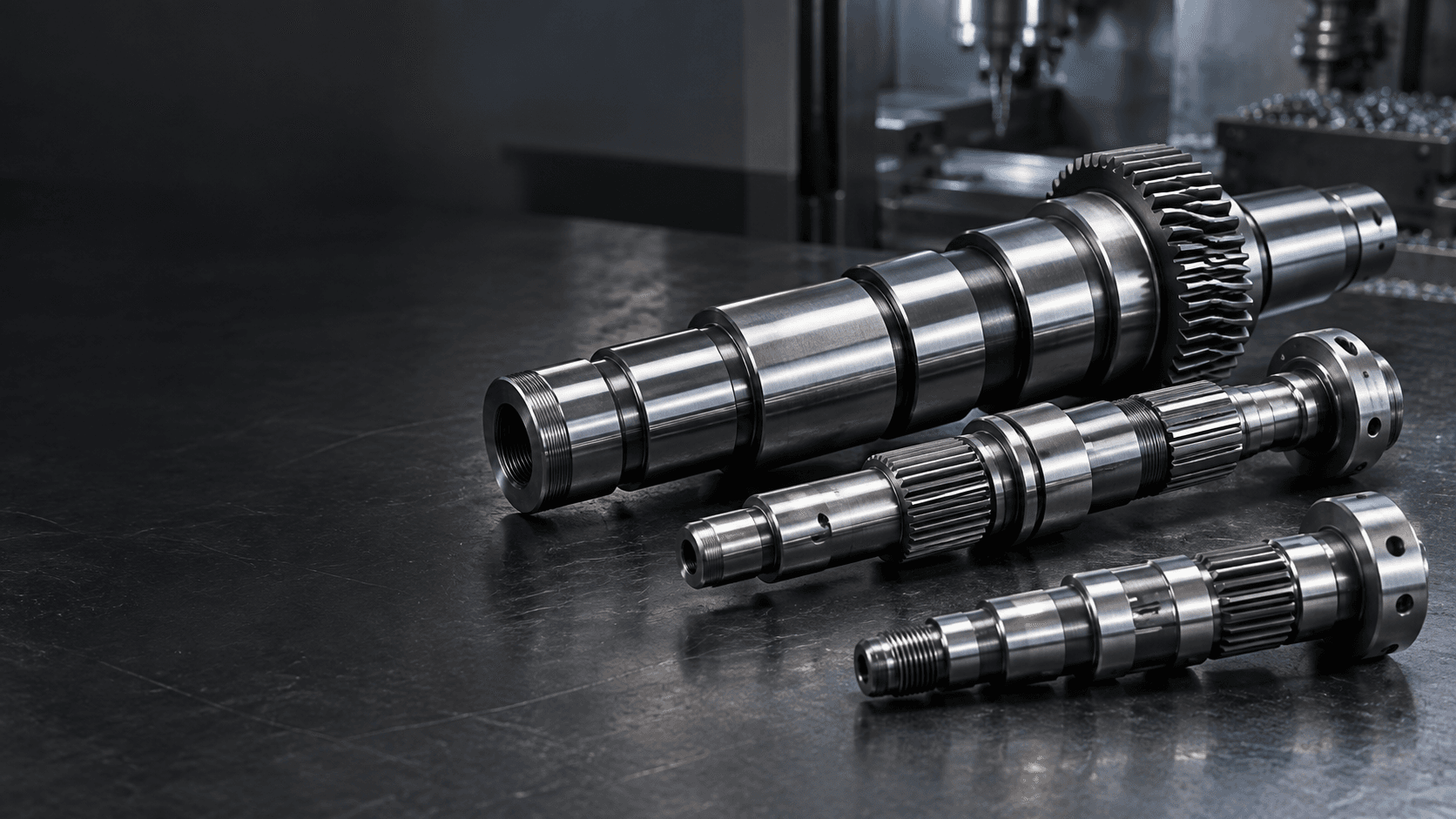
CUSTOM STEPPED SHAFT MANUFACTURER
Custom Stepped
Shafts
Multiple diameters built around your assembly.
Custom stepped shafts with multiple precision diameters, locating shoulders and functional fits for bearings, gears, seals, couplings and OEM mechanical assemblies.We review the relationship between every step, shoulder, datum and critical fit—not each diameter in isolation.
For faster review, identify bearing seats, critical shoulders, ground surfaces and fit requirements.STEPPED SHAFT ENGINEERING SNAPSHOT
One shaft can carry many functional fits.
Each diameter and transition needs to support the component mounted on it—and the relationships between them.- Core geometry
- Multiple precision diameters connected by functional shoulders
- Interfaces
- Bearing seats, gear seats, seal journals, couplings and clearance zones
- Critical relationships
- Step lengths, shoulder faces, fillets and inter-step alignment
- Manufacturing
- CNC step turning, secondary features, treatment and selective grinding
- Inspection
- Diameters, axial positions, runout, straightness and surface condition
- Project review
- Fits and datums evaluated around the complete assembly path
WHAT IS A STEPPED SHAFT?
A geometry architecture for multiple mechanical interfaces.
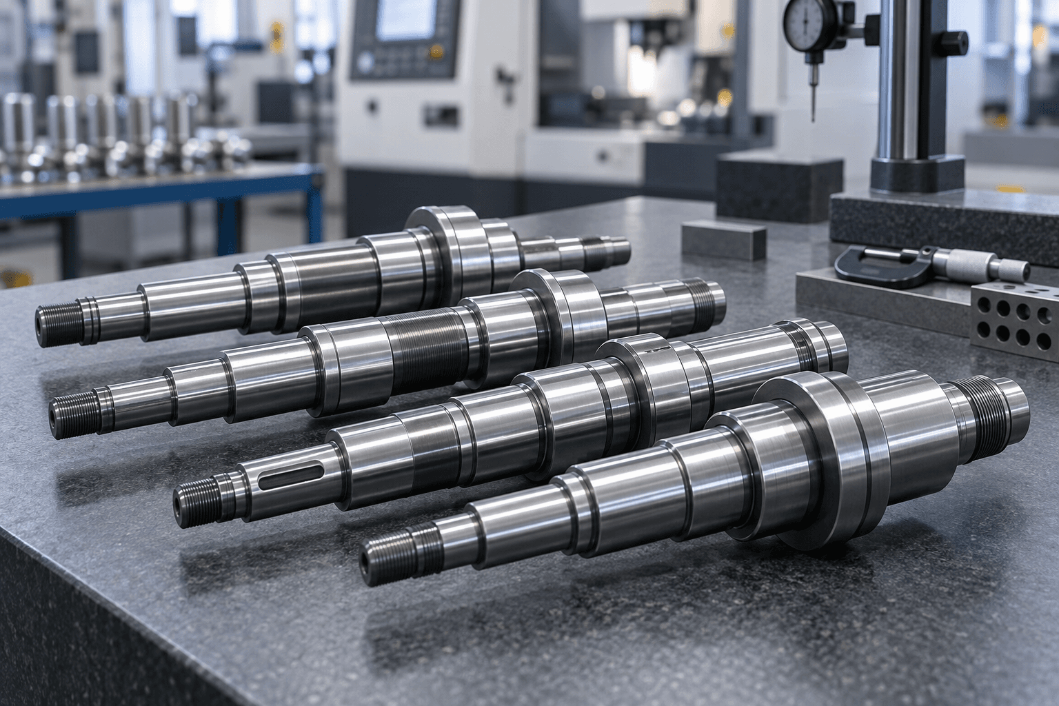
A stepped shaft has two or more cylindrical sections of different diameters joined by shoulders. The individual steps can support bearings, gears, seals, spacers, pulleys or coupling components on one common shaft.
Stepped shaft describes the part’s geometry rather than one operating role. That makes shoulder locations, transition geometry and the relationship between functional diameters central to the drawing review.
FUNCTIONAL ZONES
What can each stepped diameter do?
Locating shoulders
Axial stops that position bearings, gears, spacers and mounted components.Gear & coupling seats
Functional diameters that locate or transmit through fitted components.Seal journals
Surface zones selected around seal contact, finish and wear requirements.Clearance sections
Non-functional diameters that allow assembly movement without adding unnecessary cost.Transitions
Fillets, reliefs and undercuts that balance stress, tool access and component clearance.MANUFACTURING ROUTE
How are stepped shafts manufactured?
The process is planned around the functional relationships that must remain true after every machining and treatment stage.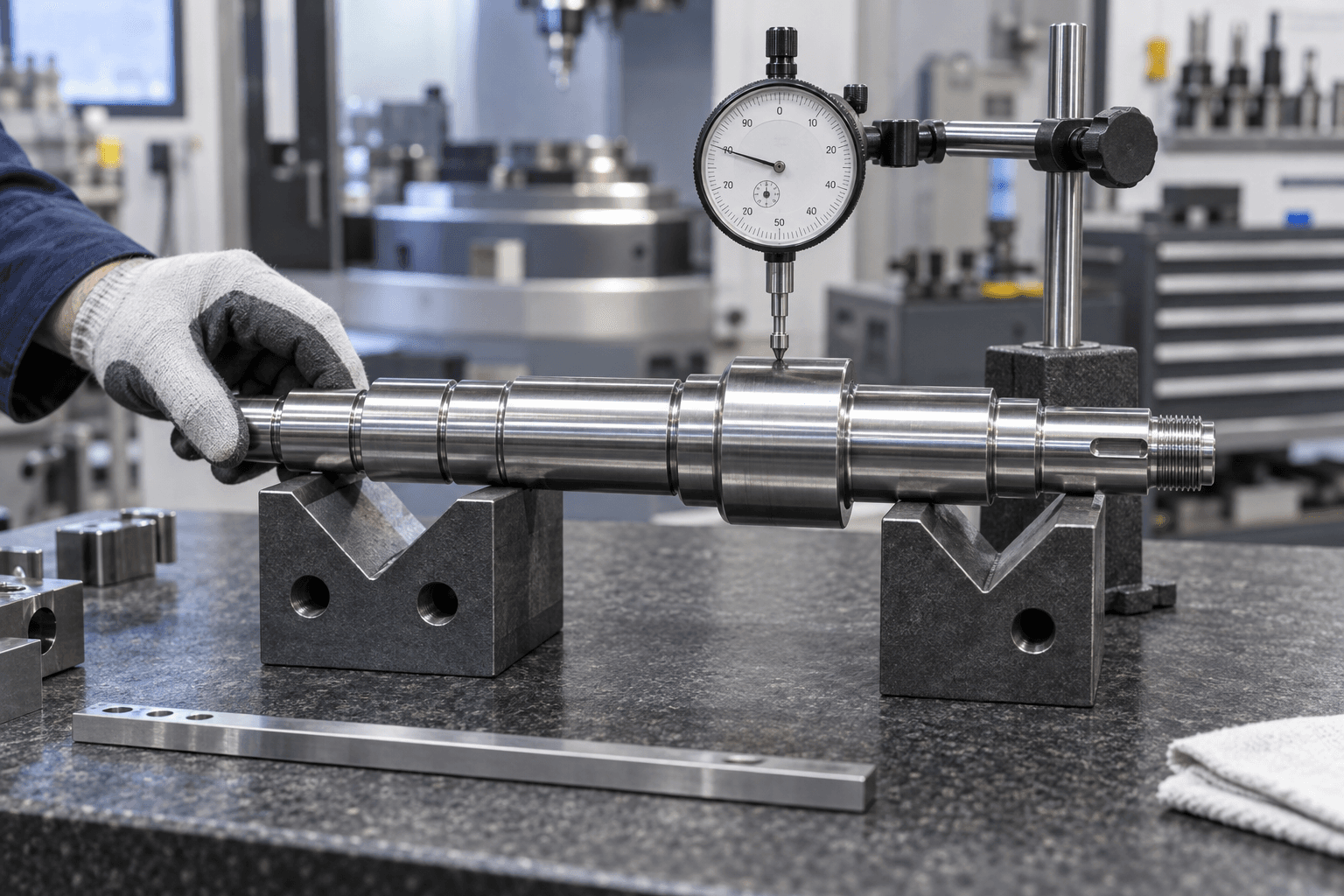
COMMON ROTATIONAL AXIS
Size tolerance alone is not enough.
Mounted components on different steps commonly need to rotate around the same functional axis. Inter-step runout and shoulder-face geometry can therefore matter as much as each nominal diameter.- Step diameters and bearing or coupling fit surfaces
- Step lengths and axial shoulder locations
- Inter-step runout, straightness and relevant coaxiality
- Shoulder face squareness and component seating
- Fillet radius, relief groove and surface-finish requirements
SHOULDERS AND TRANSITIONS
Small details can determine whether the assembly seats correctly.
A shoulder provides an axial locating surface. Its face needs to suit the mounted part, while its fillet or relief must avoid interfering with a bearing or component corner radius.Different fits on one part
A bearing journal, gear seat and clearance diameter can have different tolerances because they perform different jobs. Precision is applied where it creates function.
Protect the reduced section
The smallest step, particularly beside a shoulder, keyway, groove or hole, can become a critical stress area. Transition geometry is reviewed together with material and duty.
APPLICATION CONTEXT
Where are custom stepped shafts used?
Gearboxes & reducers
Bearings, gears and seals located along one common shaft.Electric motors
Rotor, bearing, fan and coupling interfaces with distinct diameter requirements.Automation machinery
Compact assemblies combining journals, pulleys, gears and custom features.Pumps & compressors
Rotating shafts with seal surfaces, bearing seats and drive connections.Material handling
Roller, conveyor and transmission components built to drawing.Industrial equipment
Special-purpose OEM assemblies requiring multiple fit zones.RELATED SHAFT TYPES
Geometry and function are not the same thing.
Stepped Shaft vs. Transmission Shaft
Stepped shaft describes multi-diameter geometry. Transmission shaft describes a power-transfer function; a transmission shaft may also be stepped.Explore →Stepped Shaft vs. Spindle Shaft
A spindle may contain steps, but is engineered principally around bearing alignment, nose geometry, stiffness and working runout.Explore →Stepped Shaft vs. Gear Shaft
A gear shaft includes integral gear teeth. A stepped shaft can instead carry a separate mounted gear on a defined seat.Explore →Stepped Shaft vs. Custom Precision Shaft
Custom precision shaft is the broader category; stepped shaft focuses specifically on diameter transitions and locating shoulders.Explore →PREPARE YOUR RFQ
What is needed for a stepped shaft quote?
A 2D drawing or 3D model with the functional context helps us plan the right route.- 01Overall length, every step diameter and step length
- 02Shoulder locations, fillet radii, reliefs, bores and tapers
- 03Bearing, gear, seal, coupling and clearance interfaces
- 04Keyways, splines, threads, grooves, holes and secondary features
- 05Fits, diameter tolerances, runout, straightness and GD&T
- 06Material, heat treatment, hardness and surface finish
- 07Prototype or production quantity and inspection documentation
STEPPED SHAFT FAQS
Common engineering questions.
Practical guidance for engineering and sourcing teams reviewing multi-diameter shaft designs.What is a stepped shaft?+
It is a shaft with two or more cylindrical sections of different diameters connected by shoulders. The sections can support bearings, gears, seals, couplings and other mechanical components.
Why are shoulder faces important?+
They create the axial reference that positions a mounted component. Their location and face geometry affect how the assembly seats.
Can different steps have different tolerances?+
Yes. Bearing journals, gear seats, seal surfaces and clearance sections can each require a different tolerance or finish based on function.
Can stepped shafts be ground?+
Yes. Grinding can be used selectively on critical journals or post-heat-treatment surfaces where the drawing requires tighter geometry or finish.
Why inspect runout between steps?+
Components installed on separate diameters may need a common rotational relationship. Inter-step runout helps control that relationship.
READY TO START?