Material where it matters
Combine a tubular central body with solid bearing journals, flanges or spline ends.

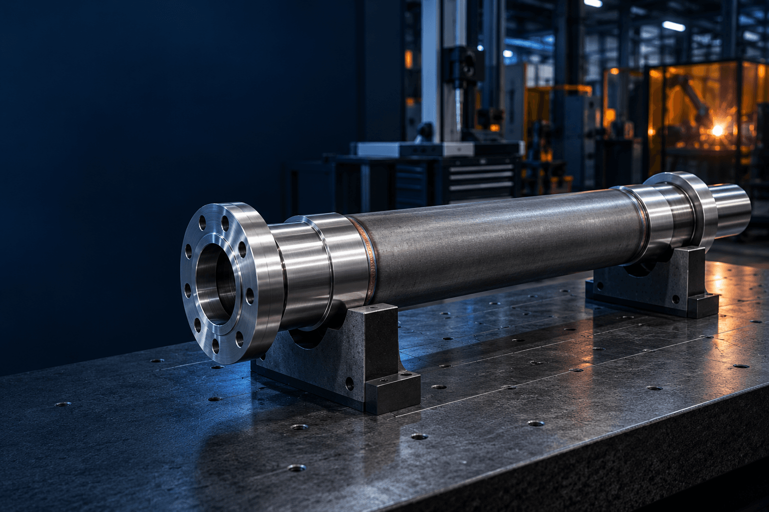
CUSTOM WELDED SHAFT MANUFACTURER
Topshaft supplies drawing-based welded shafts for machinery, gearbox, drive and rotating-equipment applications where the joint, final axis and functional interfaces must work together.
Depending on the application, the manufacturing route can combine rotary friction welding or project-specific fusion welding with CNC turning, boring, milling, grinding and final inspection.
Send the finished drawing, materials, joint location, critical tolerances, inspection requirements and quantity for engineering review.WELDED SHAFT MANUFACTURING AT A GLANCE
Actual joint design, welding process, heat input, machining allowance, alignment control and inspection scope depend on the component geometry, materials and finished drawing requirements.
WHAT IS A WELDED SHAFT?
A welded shaft joins two or more separately prepared components into one rotating assembly. Common constructions include tube-to-journal, tube-to-flange, stub-to-hub and multi-piece drive assemblies.
The weld is not treated as the final geometry. After joining, machining and—where required—grinding establish the bearing fits, bores, shoulders, coupling interfaces, runout and straightness that the application actually uses.
WHY USE A WELDED SHAFT?
A welded route can create practical engineering and supply advantages without making a blanket claim that it is the right answer for every rotating component.
Combine a tubular central body with solid bearing journals, flanges or spline ends.
A tube-based construction can avoid machining a long hollow form from a solid billet.
Machine different ends for bearings, couplings, gears, splines, seals or mounting interfaces.
Make large or long forms from components that are practical to source, handle and machine.
Evaluate compatible materials or properties only after joint-design and qualification review.
Restore critical datums with CNC turning, boring and grinding after joining.
Joint Design → Material Compatibility → Welding Process → Alignment → Post-Weld Machining → Runout / Straightness → Inspection
FRICTION-WELDED SHAFTS
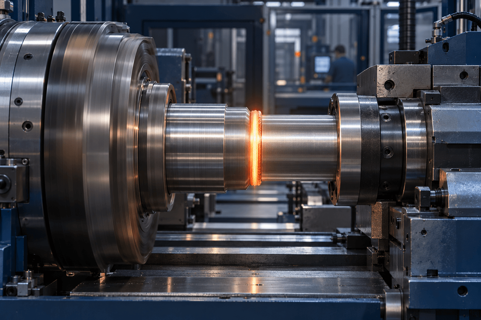
Rotary friction welding joins aligned components through relative rotation and axial force. The interface is heated by friction and consolidated under pressure rather than by depositing filler metal into a molten weld pool.
For suitable material pairs and rotational geometries, it can offer a repeatable, controlled route for tube-to-end, bar-to-flange and journal-to-body constructions. Flash removal, joint upset, material flow and post-weld machining allowance are considered as part of the design.
FRICTION WELDING VS. FUSION WELDING
Both methods can be relevant. The right route is selected around the finished part, not a generic preference.
WELDED SHAFT CONSTRUCTION OPTIONS
A tubular body joined to solid bearing or seal journal ends.
A tubular member joined to a mounting or torque-transfer flange.
Short shaft stubs joined to a hub, coupling or drive interface.
A longer assembly with functional sections joined in practical locations.
Tube construction with machined bores, shoulders and connection features.
Reviewed carefully where welding, material history and service condition permit.
WELDED SHAFT VS. ONE-PIECE SHAFT
One-piece, forged and welded shaft routes can all be technically sound. The choice should account for torque, bending, fatigue, joint location, materials, quantity, machining access and the cost of the complete manufacturing route.
Welded shaftUseful when a tube body, specialized ends or an assembly-scale route creates a practical advantage.
One-piece machined shaftOften direct for smaller, simple or low-volume geometry where the entire form can be machined efficiently from one blank.
Forged shaftMay suit high-load or large-section components where the forged starting blank supports the intended material and geometry route.
MATERIALS & FUNCTIONAL GEOMETRY
Carbon steel, alloy steel and stainless steel can be considered, subject to material compatibility and required process control. The final geometry can include bearing journals, splines, threads, keyways, bores, shoulders, seal seats and coupling interfaces.
Critical features should be specified from functional datums. Joint placement should avoid unnecessary concentration of load, distortion-sensitive sections and finish-critical surfaces where possible.
POST-WELD MACHINING & HEAT-AFFECTED ZONES
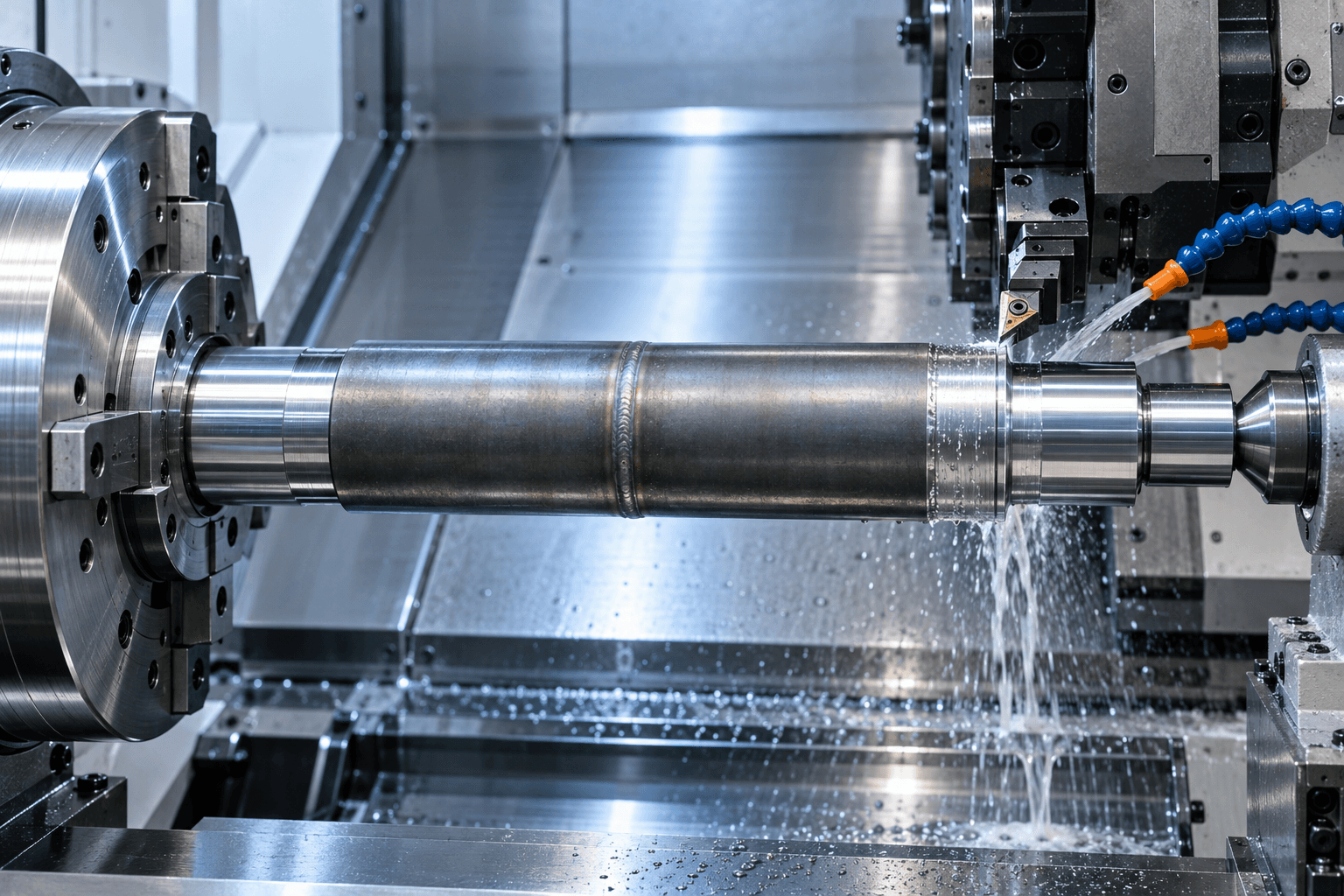
Welding can change straightness, local hardness, residual stress and dimensional relationship. The post-weld route can include straightness checks, stress relief when required, CNC turning, boring, milling and finish grinding.
The heat-affected zone is not a generic pass/fail condition. Its relevance depends on material chemistry, welding process, section thickness, heat input, cooling rate, service load and any procedure or qualification requirements. For high-duty or safety-critical applications, agree the required WPS/PQR, examination and acceptance criteria before production.
Post-weld journal and bore machining
Straightness, concentricity and runout control
Heat treatment or stress relief where specified
Grinding after thermal processing where required
CUSTOM WELDED SHAFT MANUFACTURING ROUTE
Welding is integrated with material traceability, datum strategy, thermal control, precision machining and final inspection.
ALIGNMENT, RUNOUT & INSPECTION
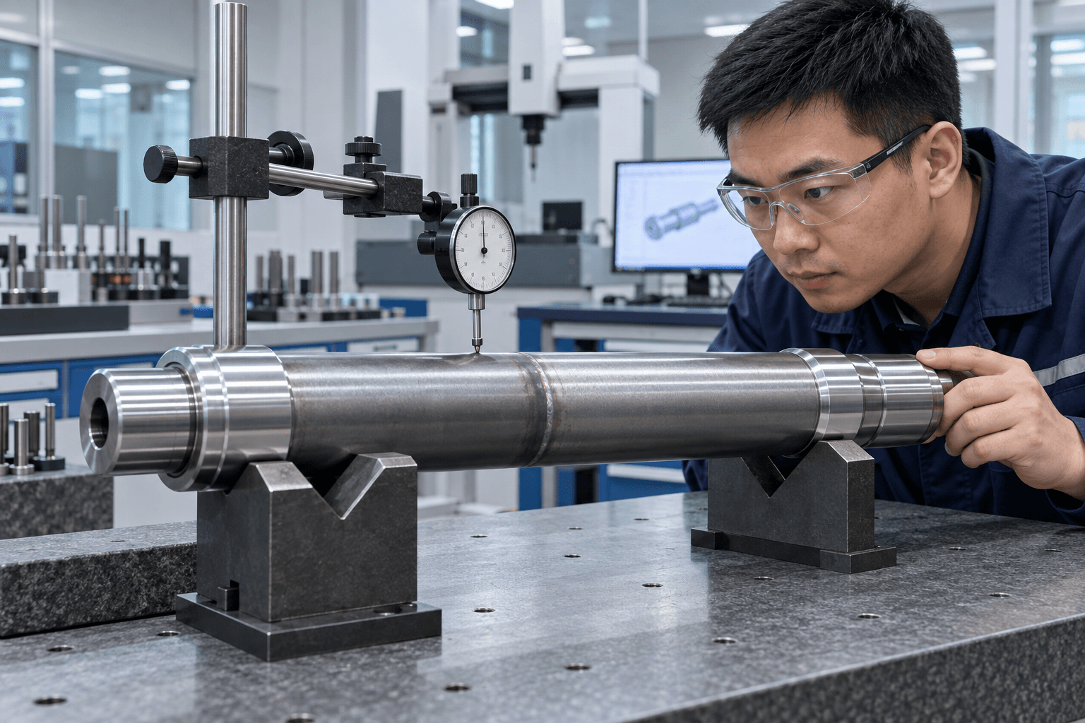
Inspection is organized around the features the assembly uses: bearing-journal diameters, journal-to-journal relationship, shoulder locations, bore concentricity, straightness, total indicated runout and surface roughness.
Depending on the order, the plan can include visual examination, dimensional records, runout checks, hardness testing, magnetic-particle or ultrasonic examination, weld-related records and customer-specific documentation. ISO 15620:2019 or AWS C6.2/C6.2M:2021 may be relevant only when specified by the project.
WELDED SHAFT APPLICATIONS
Tubular or multi-piece shafts for torque transmission, couplings and bearing-supported systems.
Tube, hub, flange and journal combinations for industrial drive assemblies.
Shaft assemblies reviewed for seals, corrosion conditions, bearing fits and runout.
Long or assembly-scale rotating members with practical material and machining routes.
Drive constructions assessed for torque reversals, shock and cyclic loading.
Project-specific shafts where geometry, traceability and inspection must be coordinated.
WHAT TO INCLUDE IN A WELDED SHAFT RFQ
A finished drawing or 3D model is the best starting point. Include the joint and post-weld precision requirements—not just the overall length.
WELDED SHAFT FAQS
A welded shaft is a multi-piece rotating component in which two or more shaft sections are joined before final machining. The finished function depends on joint design, material compatibility, welding method and post-weld control of the final axis.
Neither process is universally stronger. Rotary friction welding is a solid-state process that can be highly repeatable for compatible rotational parts, while fusion welding may suit joints or assemblies that cannot be friction welded. The applicable route follows the drawing, materials, load case and qualification requirements.
Yes. Post-weld turning, boring, milling and grinding are commonly used to establish final journals, bores, shoulders, threads and other functional interfaces around the final datum axis.
The joint location, locating features, welding setup, straightness control and post-weld machining strategy are reviewed together. Critical journals can be finish-machined or ground after welding and any specified thermal processing.
Some combinations can be considered, but material compatibility, joint design, thermal behavior, corrosion conditions and qualification requirements must be reviewed first. Do not assume that all steel or dissimilar-metal pairs are weldable for a rotating application.
The scope can include visual examination, dimensional inspection, runout and straightness checks, hardness testing, surface roughness, magnetic-particle or ultrasonic examination and customer-specific records where agreed.
A welded construction can be useful when it reduces material waste, combines a tube with solid functional ends, enables different features or materials, or makes a large assembly more economical. A one-piece or forged route may be more appropriate for other load paths.
Provide the finished drawing or CAD model, material specifications for each component, joint location, load and service conditions, welding-process preference if any, critical tolerances, inspection requirements, documentation and quantities.
NEED A CUSTOM WELDED SHAFT?
Topshaft can review joint design → material compatibility → welding route → post-weld machining → runout / straightness → inspection. Include your drawing, material specification, quantity and any weld, NDT or documentation requirements.