High torque and mechanical load
A suitable forged blank can provide a robust starting structure for drivetrain and machinery shafts under torsional and bending load.

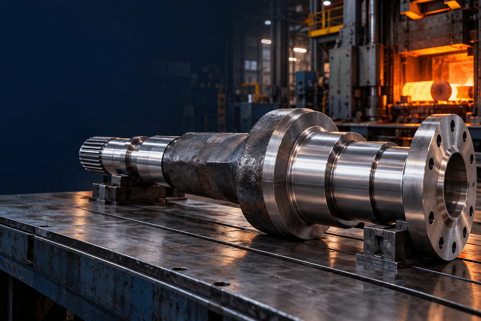
CUSTOM FORGED SHAFT MANUFACTURER
Topshaft coordinates forged blanks, heat treatment and precision machining for gearbox, drivetrain, heavy-machinery and energy applications.
CNC turning, milling, gear or spline machining, grinding, NDE and final inspection are reviewed around your finished drawing.
Send your drawing, material specification, required quantity, heat-treatment requirements and critical tolerances for engineering review.FORGED SHAFT MANUFACTURING AT A GLANCE
Actual forging size, machining envelope, tolerances, inspection scope and achievable surface finish depend on the shaft geometry, selected alloy, forging route and finished drawing requirements.
WHAT IS A FORGED SHAFT?
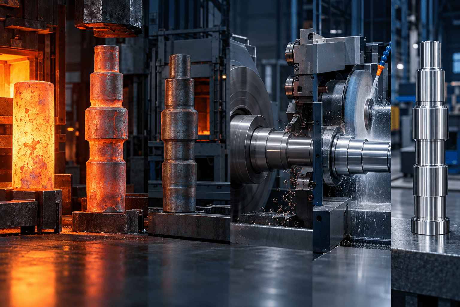
A forged shaft is a shaft whose load-bearing blank is shaped by compressive metalworking before final machining. Rather than removing the complete shape from bar stock, forging redistributes material and can create directional grain flow.
Depending on the alloy, component geometry and forging process, properly developed grain flow can contribute to fatigue resistance, impact toughness and ductility. But “forged” does not automatically mean stronger in every application: material grade, forging reduction, grain-flow orientation, heat treatment, defect control, shaft geometry and operating load all matter.
WHY USE A FORGED SHAFT?
Forged shafts are especially relevant when the quality of the starting blank matters as much as the precision of the final machining.
A suitable forged blank can provide a robust starting structure for drivetrain and machinery shafts under torsional and bending load.
Shoulder transitions, splines, gear sections and diameter changes can be fatigue-sensitive areas in rotating shafts.
Off-highway equipment, agricultural machinery and industrial drives can require material toughness under sudden torque changes.
A shaped forging can place material nearer large journals, flanges and major diameter transitions.
A forged blank can reduce material removed from a very large billet when quantity, tooling and geometry justify the route.
Bearing journals, coupling seats, bores, threads and ground interfaces are created by subsequent machining and grinding.
Forging should be selected when the shaft application benefits from the forged starting structure, geometry or production route—not simply because forging sounds stronger than machining.
FORGED SHAFT VS. BAR-STOCK MACHINED SHAFT
For many small or straightforward shafts, bar-stock machining can remain more economical. Forged blanks can be meaningful for highly loaded, larger or more complex components.
OPEN-DIE VS. CLOSED-DIE FORGED SHAFTS
Open-die forging shapes heated metal between dies without completely enclosing it in a dedicated cavity. It is particularly suitable for straight shaft blanks, stepped shafts, spindles, hollows, large-section shafts and custom low- or medium-volume forgings.
Closed- or impression-die forging uses shaped dies to produce a blank closer to the required geometry. It can be attractive where production quantity justifies tooling, repeatability matters or reducing machining stock provides a production advantage.
The route is evaluated with the forging supplier and customer requirements rather than defaulting to one method.
FORGED SHAFT FORMS
Primarily cylindrical geometry for industrial drive and transmission shafts.
Material concentrated around journals, gear seats, shoulders and coupling sections.
Enlarged ends for bolt mounting, torque connection or structural attachment.
Evaluated around required OD, ID, wall geometry and internal routing.
Larger bearing or rotor sections before precision machining and grinding.
Reviewed where volume, section size and load justify a near-net blank.
MATERIALS FOR FORGED SHAFTS
Material selection follows the shaft's load, fatigue requirement, wear, heat treatment, environment and applicable material standard.
General industrial shafts where strength, machinability and cost need balance.
4140 / 42CrMo and customer-specified Cr-Mo or Ni-Cr-Mo alloys for strength, toughness and heat-treatment response.
4340 / Ni-Cr-Mo families can be evaluated where the project requires higher strength or toughness.
For gear, pinion and spline shafts requiring a hard wear surface and tougher supporting core.
Where corrosion resistance is required and the grade, forging route and treatment are available.
The customer drawing, purchase specification and applicable product standard control the forging requirements. ASTM A668/A668M and ASTM A788/A788M may be relevant where specified; they are not applied automatically to every forged shaft.
FROM FORGED BLANK TO FINISHED PRECISION SHAFT
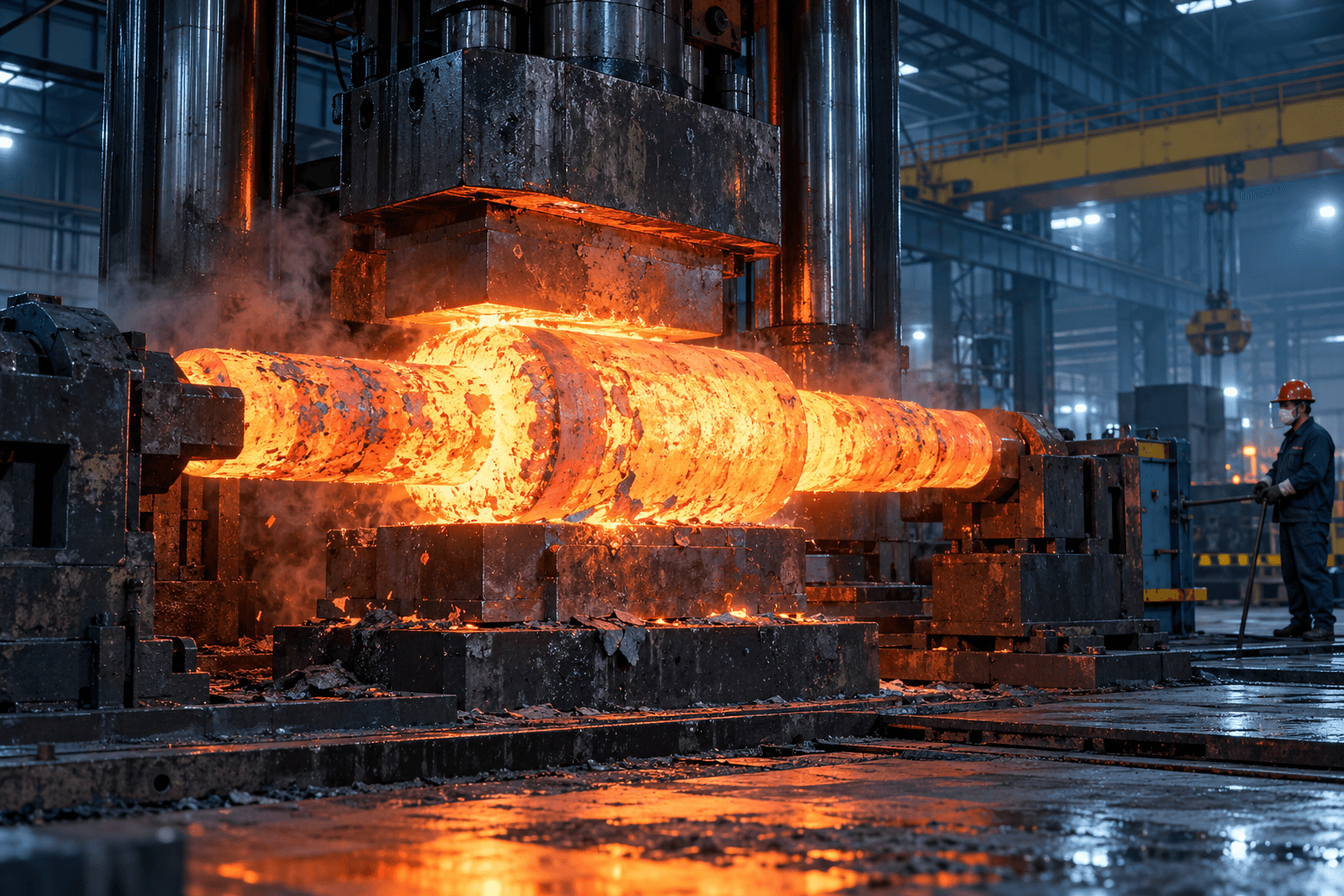
Forging and heat treatment are one connected material-processing route. The exact sequence varies by material, forging standard, geometry and finished dimensional requirements.
HEAT TREATMENT, MACHINING ALLOWANCE & GRINDING
Normalizing can establish a controlled material condition. Quenching and tempering is relevant to alloy-steel shafts requiring strength and toughness. Carburizing can support hard wear surfaces on gear and spline shafts; induction hardening can be applied to selected journals, splines or coupling areas. Stress relieving may support dimensional stability.
A forging is not normally produced directly to final bearing-journal dimensions. Stock is retained for scale removal, surface cleanup, heat-treatment movement, straightness correction, final turning and grinding. Finished and forging drawings should be reviewed together where possible.
CNC turning produces bearing journals, stepped diameters, shoulders, seal surfaces, threads, grooves and gear seats. Milling creates keyways, flats, cross holes and mounting features; bores, splines and gear teeth are created where technically feasible.
Thermal processing can change straightness, diameter, roundness and residual distortion. Critical surfaces can retain finishing allowance until post-treatment geometry checks, then be ground to the final fit, roundness, cylindricity and roughness requirement.
Forge → Heat Treat → Rough Machine → Final Heat Treat → Geometry Check → Finish Grind → Inspect
FORGING QUALITY, NDE & FUNCTIONAL DATUMS
Critical bearing-journal diameter, roundness, cylindricity, journal-to-journal relationship, straightness, runout, shoulder position and surface roughness are organized around the final functional shaft datum.
Some projects also require ultrasonic examination, magnetic-particle examination, hardness testing, mechanical-property testing, chemical analysis or customer-specific forging acceptance requirements. ASTM A388/A388M and ASTM A275/A275M may be applicable when UT or MPI is specified.
Explore inspection & quality support →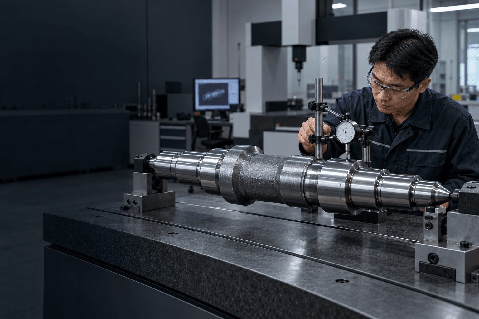
MATERIAL TRACEABILITY & FORGING DOCUMENTATION
For higher-duty projects, documentation can be as important as dimensional inspection. Requirements should be agreed before forging begins.
FORGED SHAFT APPLICATIONS
Input, intermediate, output, gear and spline shafts reviewed around torque, bending, fatigue, bearing journals and interfaces.
Explore related solution →Heavy drives, processing equipment and large mechanical systems subjected to torque, shock, continuous duty and bearing loads.
Explore related solution →Near-net forging can support substantial shaft journals combined with an integral gear or pinion section.
Explore related solution →Offset, fatigue-critical components where material flow and cyclic-loading performance are important.
Explore related solution →Drive, transmission and gearbox shafts evaluated for shock, changing torque, impact and fatigue.
Explore related solution →Generator, gearbox and industrial energy equipment where size, NDE and mechanical properties are confirmed project by project.
Explore related solution →WHAT INFORMATION IS NEEDED FOR A FORGED SHAFT QUOTE?
Providing the complete finished-part drawing is usually the fastest way to start the review.
FORGED SHAFT FAQS
A forged shaft is made from a metal blank shaped through compressive forging before final machining. The blank is then machined and finished to create bearing journals, steps, threads, gears, splines or other functional features.
Not automatically. Forging can create favorable directional grain flow and can support fatigue, impact and mechanical performance in suitable designs, but finished strength still depends on alloy, heat treatment, forging quality and shaft geometry.
Forged shafts are often considered for heavy-load, fatigue-sensitive, shock-loaded, large-section or near-net-shape applications where a forged starting blank offers engineering or manufacturing advantages.
Open-die forging provides flexibility for custom and larger shaft shapes without fully enclosing the material in a die cavity. Closed/impression-die forging uses shaped tooling and can be attractive for repeat production of developed near-net geometries.
Common directions include carbon steels, alloy steels, carburizing steels and application-specific forged grades. The exact material follows load, fatigue, heat treatment and the applicable specification.
Yes. The forged blank can subsequently be machined with gear teeth, splines, keyways, threads, axial bores and other transmission features where the project geometry permits.
Heat treatment can change dimensional and geometric characteristics. Precision grinding may be used after thermal processing to achieve the final bearing-journal diameter, roundness, cylindricity and surface finish.
Yes, when required by the customer specification or applicable standard. The required NDE method, acceptance criteria and documentation should be defined by the drawing, forging standard or order requirements.
Provide the finished drawing or CAD model, material and forging standard, heat treatment, quantity, mechanical-property requirements, tolerances, NDE requirements, documentation and application information.
NEED A CUSTOM FORGED SHAFT?
Topshaft can review forging route → material → machining allowance → heat treatment → precision machining → inspection. Include annual demand and any required material, mechanical-testing or NDE standards.