
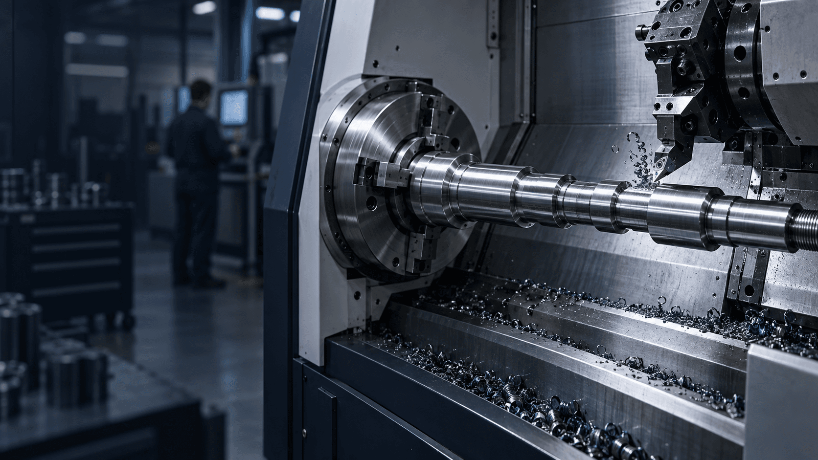
CNC SHAFT MACHINING
CNC Turning For Precision Shafts & Complex Features.
From Rotational Geometry To Complete Shaft Features.
TOPSHAFT provides CNC turning and secondary machining for custom precision shafts manufactured directly from customer drawings.We machine bearing journals, stepped diameters, shoulders, grooves, threads, bores, tapers and locating surfaces, then coordinate keyways, flats, cross holes and other drawing-defined details where required.
Send your 2D drawing, 3D model, material, quantity and critical tolerances for manufacturing review.CNC SHAFT TURNING CAPABILITIES
A Manufacturing Route Built Around The Shaft Axis.
We plan the route around functional rotational relationships, not just isolated dimensions. Actual machine limits and part feasibility are confirmed during drawing review.| Capability area | Typical TOPSHAFT support |
|---|---|
| Main process | CNC turning and precision turning for drawing-defined shaft geometry. |
| Typical components | Motor, stepped, drive, transmission, spindle, roller, threaded and custom shafts. |
| Turned features | OD, ID, shoulders, faces, grooves, threads, tapers and bores. |
| Secondary features | Keyways, flats, slots, radial holes, cross holes and drawing-defined details. |
| Materials | Carbon steel, alloy steel, stainless steel, aluminum and specified materials. |
| Precision control | Diameter, fit, runout, coaxiality, roundness and surface finish according to drawing. |
| Secondary processing | Milling, grinding, heat treatment and surface finishing where required. |
| Production stage | Prototype through repeat OEM production. |
| Inspection | Drawing-defined dimensional and geometric inspection. |
WHAT IS CNC TURNING FOR SHAFT MANUFACTURING?
Turn The Functional Geometry First.
CNC turning is a subtractive machining process in which the workpiece rotates while cutting tools produce cylindrical and rotational features. For shaft manufacturing, it creates outside diameters, bearing journals, shoulders, grooves, threads, tapers, faces and internal bores.For TOPSHAFT, the objective is not simply to turn a round part. The process route is planned around the functional shaft axis and the relationship between critical diameters and features.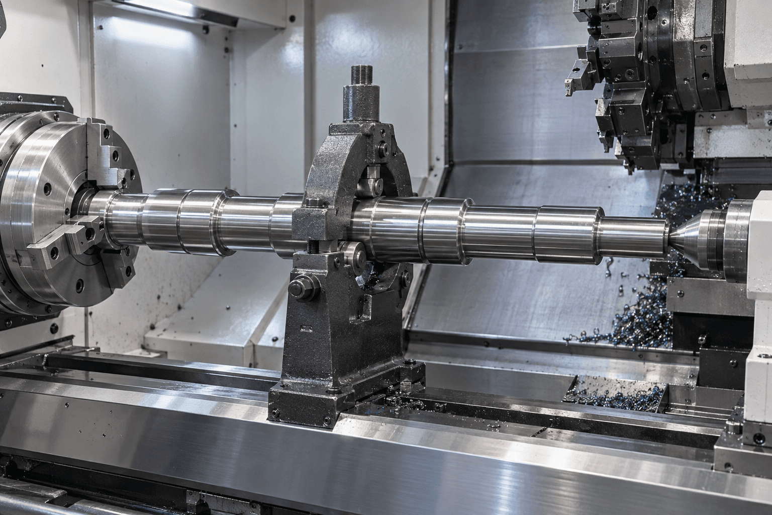
TURNED SHAFT FEATURES
What CNC Turning Can Produce.
Outside diameters
Bearing journals, rotor seats, gear seats, coupling seats and seal journals.Stepped diameters
Multiple functional fits generated around a common rotational axis.Shoulders & faces
Axial locations for bearings, gears, spacers and couplings.Grooves
Retaining-ring, seal, relief and snap-ring features.External threads
Retaining nuts, assembly interfaces and threaded shaft ends.Internal threads
End mounting, assembly hardware and internal retention.Tapers
Locating, clamping and mating interfaces.Internal bores
Hollow shafts, weight reduction, through-axis routing and mechanical integration.TURNING PLUS SECONDARY FEATURES
When Rotational Geometry Is Not The Whole Drawing.
Turning is rotationally symmetric. Many shafts also need non-rotational interfaces. Live tooling or a coordinated secondary operation is selected according to geometry and the relationship that needs to be preserved.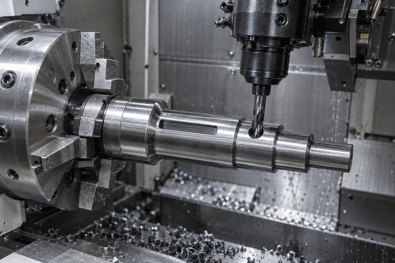
Keyways
Machined for keyed torque transmission.Flats
For set screws, couplings and positioning.Cross holes
For pins, lubrication and assembly features.Radial tapped holes
For locking and assembly requirements.Slots & end features
For application-specific interfaces, bolt patterns and mounting geometry.Splines & gear features
Typically require dedicated spline or gear manufacturing beyond basic turning.TURNING VS. TURN-MILL VS. SECONDARY MACHINING
Which Process Does Your Shaft Need?
Process selection follows the actual part geometry and approved drawing—not a turning-only assumption.| Part geometry | Recommended route |
|---|---|
| OD + shoulders + grooves | CNC turning |
| OD + external thread | CNC turning |
| Shaft + internal bore | CNC turning / boring |
| Shaft + keyway | Turning + milling |
| Shaft + flat | Turning + milling |
| Shaft + cross hole | Turning + drilling / live tooling |
| Shaft + radial thread | Turn-mill / secondary machining |
| Small slender shaft | Swiss-type evaluation |
| Bearing journals after hardening | Turning + heat treatment + grinding |
| Integral spline | Turning + spline machining |
| Integral gear | Turning + gear machining |
FUNCTIONAL SHAFT DATUMS
Why Does The Shaft Axis Matter?
Bearings, gears and rotor seats can each meet a size tolerance while still being incorrect as an assembly if their rotational relationship is poor. CNC shaft turning therefore needs to consider a common datum axis, feature sequence, workholding, re-clamping, runout, coaxiality and shoulder relationships.Bearing journal A→Gear / rotor seat→Bearing journal B
Diameter tolerance vs. shaft geometry
BEARING JOURNALS
Often The Most Important Turned Surface.
Critical journal requirements can include diameter, fit class, roundness, cylindricity, runout, surface roughness and shoulder position. Depending on the required fit, material condition and post-heat-treatment route, a bearing journal may be finish-turned or subsequently ground.Read bearing journal specifications →STEPPED & MULTI-DIAMETER SHAFTS
Natural Components For CNC Turning.
Several cylindrical diameters and shoulders can be generated around one rotational axis. Bearing seats, gear seats, seal journals, coupling sections and threaded ends are then reviewed as a connected geometry.Explore stepped shafts →LONG & SLENDER SHAFT TURNING
Support The Geometry During Machining.
As length-to-diameter ratio increases, machining becomes more sensitive to deflection, chatter, tool pressure, straightness and workholding. Tailstock support, steady rests, controlled cutting parameters, staged rough/finish cuts, intermediate inspection and final grinding may be considered where appropriate.HOLLOW SHAFT CNC TURNING
Review OD, ID And Their Relationship.
Hollow shafts can require drilling, boring, turning and a controlled relationship among outside diameter, internal bore, wall thickness and bore concentricity. The drawing should identify which interfaces are functional.Explore hollow shafts →MATERIALS FOR CNC SHAFT TURNING
Match The Material To The Function.
Final material grade follows the customer's drawing. Machining route, treatment and finishing are reviewed against strength, fatigue, wear, corrosion, temperature and functional requirements.| Material family | Common shaft application | Machining consideration |
|---|---|---|
| Carbon steel | General machine shafts | Good strength and machinability balance. |
| Alloy steel | Drive, transmission and gear-related shafts | Strength and heat-treatment route. |
| Stainless steel | Corrosion-resistant shafts | Tool wear and finish control. |
| Aluminum | Lightweight shaft components | High machinability. |
| Brass / copper alloys | Specialized shafts and components | Material-specific cutting behavior. |
| Titanium / specialty alloys | High-performance applications | Lower cutting speed and process control. |
HEAT TREATMENT + CNC TURNING
Sequence Is Part Of Precision.
Heat treatment may alter straightness and critical journal sizes. Machining allowance and post-treatment finish requirements should be planned before production.Rough turning↓Heat treatment↓Geometry check↓Finish turning / grinding↓Final inspection
WHEN DOES A TURNED SHAFT NEED GRINDING?
Use It For The Surfaces That Need It.
Finish turning may be enough when:
- Tolerance is achievable directly.
- Surface finish meets the function.
- Material remains machinable.
Grinding may be selected when:
- A functional surface is hardened.
- A tighter journal tolerance is required.
- Roundness, cylindricity or roughness needs further control.
- Post-heat-treatment finishing is specified.
CNC TURNED SHAFT TYPES
Connect The Process To The Product.
CNC turning establishes the primary rotational geometry across several shaft families. The product page explains the application; this page explains the manufacturing route.01
Motor Shafts
Bearing journals + rotor seats.→02Stepped Shafts
Multiple diameters + shoulders.→03Transmission Shafts
Journals + torque-transfer features.→04Drive Shafts
Shaft body + coupling/spline interfaces.→05Spindle Shafts
Precision journals + rotational surfaces.→06Roller Shafts
Bearing journals + long geometry.→07Threaded Shafts
Turned geometry + threads.→08Hollow Shafts
OD/ID + bore geometry.→WHEN CNC TURNING IS NOT THE WHOLE PROCESS
A Complete Shaft May Need More Than Turning.
TOPSHAFT selects the manufacturing route from the drawing rather than forcing every shaft into a turning-only process.Spline cuttingGear cuttingKeyway millingDeep-hole machiningEDMHeat treatmentGrindingSurface treatment
INSPECTION FOR CNC TURNED SHAFTS
Measure The Features That Control Function.
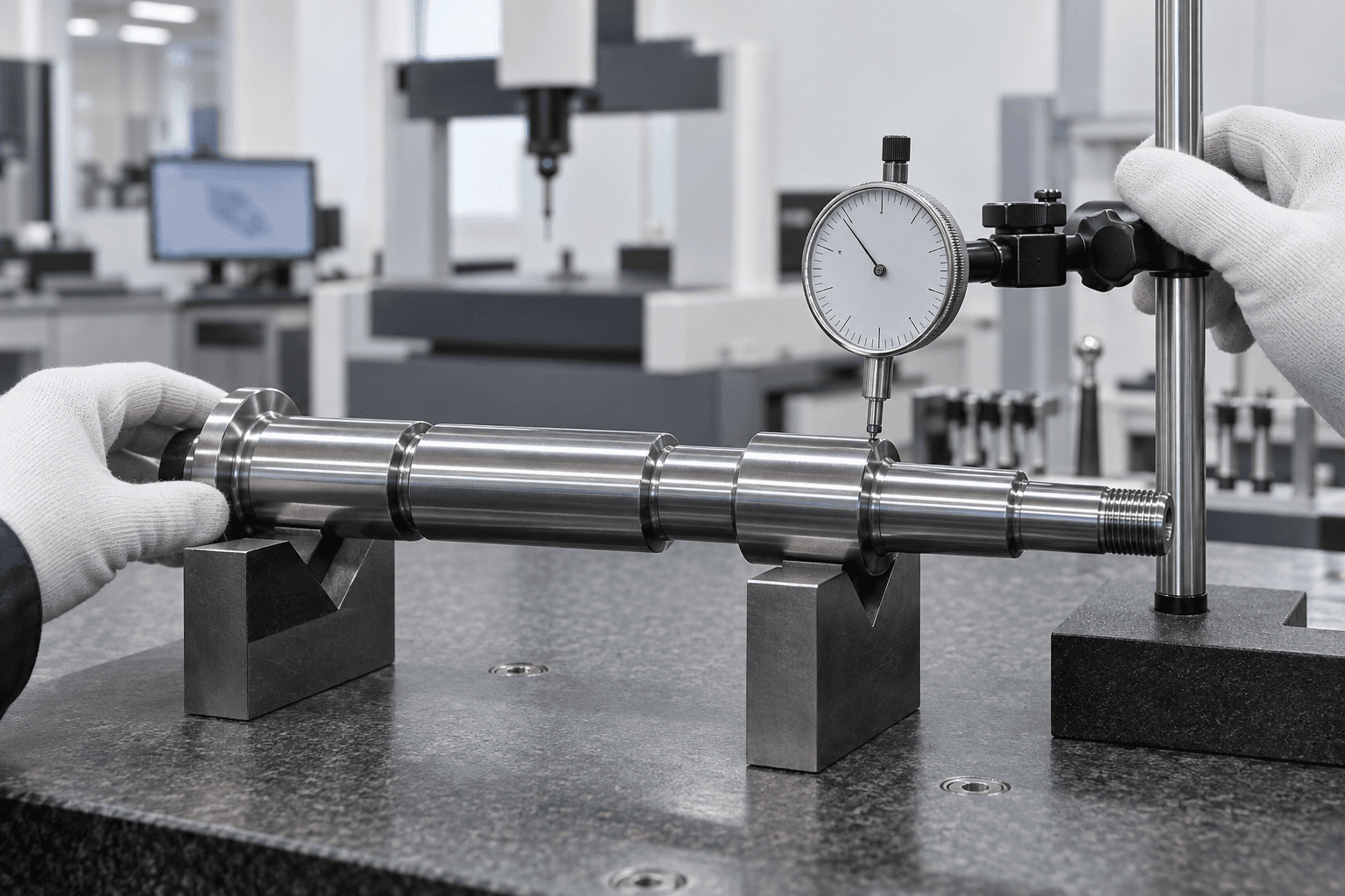
Inspection methods follow the drawing and agreed project requirements. Possible tools include micrometers, dial indicators, gauges, optical measurement, CMM and roughness testing.- OD / ID
- Overall length
- Shoulder position
- Runout
- Straightness
- Roundness
- Thread geometry
- Groove dimensions
- Surface roughness
- Bearing fits
CNC TURNING DFM FOR PRECISION SHAFTS
Specify What Is Functionally Necessary.
Useful DFM focuses manufacturing effort where it affects the actual assembly rather than applying tight requirements everywhere.Avoid unnecessary tiny corner radii
Allow a practical tool radius where the assembly permits.Provide thread relief where needed
Especially next to shoulders.Specify functional fits clearly
Identify bearings, gears, couplings and seals.Avoid blanket ±0.005 mm tolerances
Tighten dimensions that matter.Define surface roughness by function
A clearance diameter does not need the same Ra as a bearing journal.Define datum relationships
Especially for runout, coaxiality, gear seats and rotor seats.Consider tool access
Review grooves, bores and shoulder-adjacent features.Identify post-treatment dimensions
State whether tolerance applies before or after treatment or coating.WHAT INFORMATION IS NEEDED FOR A CNC SHAFT TURNING QUOTE?
Send The Data That Defines The Part.
Complete drawing, material, geometry, precision and commercial information enables a more useful manufacturing review.Upload Your Shaft Drawing →- 012D drawing, STEP / STP, DWG / DXF or PDF
- 02Material, quantity, annual demand, overall length and maximum diameter
- 03Bearing journals, bores, shoulders, grooves, threads, tapers, keyways, cross holes and flats
- 04Diameter tolerance, fits, runout, straightness, roundness, cylindricity, surface roughness and GD&T
- 05Heat treatment, grinding, plating, passivation, black oxide, anodizing or other coating
- 06Material certificate, inspection report, FAI or other customer requirements
CNC TURNING FAQS
Direct Answers For Drawing Review.
Practical questions for sourcing and engineering teams preparing a precision shaft RFQ.What is CNC shaft turning?+
CNC shaft turning uses a rotating workpiece and controlled cutting tools to make shaft diameters, bearing journals, shoulders, grooves, faces, tapers, threads and axial bores. The route is planned around the drawing-defined functional axis.
What shaft features can CNC turning produce?+
CNC turning can produce shaft diameters, bearing journals, shoulders, grooves, faces, tapers, external and internal threads, and axial bores. Off-axis features such as keyways, flats and cross holes need live tooling or secondary machining.
What types of shafts can TOPSHAFT CNC turn?+
Motor, stepped, transmission, drive, spindle, roller, threaded, hollow and custom shafts commonly use CNC turning to establish their primary rotational geometry.
What is the difference between CNC turning and turn-mill machining?+
Turning makes rotationally symmetric geometry. Turn-mill or secondary machining adds off-axis features such as flats, keyways, slots, cross holes and radial threads when the drawing requires them.
Can CNC turning control shaft runout?+
Runout control depends on datum strategy, workholding, feature sequence, re-clamping, geometry and the inspection method. Critical requirements should be defined on the drawing and reviewed before machining.
Can bearing journals be ground after CNC turning?+
Grinding may be added when the drawing requires a hardened functional surface, tighter bearing-journal geometry, improved roundness or cylindricity, or a finer final surface finish.
Can TOPSHAFT machine long or hollow shafts?+
Long, slender shafts can be reviewed around deflection, workholding, tailstock or steady-rest support, cutting sequence and inspection. Hollow shafts require OD, ID, wall-thickness and bore-concentricity review.
What files should I send for a CNC turning quote?+
Send a 2D drawing, STEP model where available, material, quantity, critical dimensions, geometric tolerances, secondary features, treatment and documentation requirements.
READY TO START?