
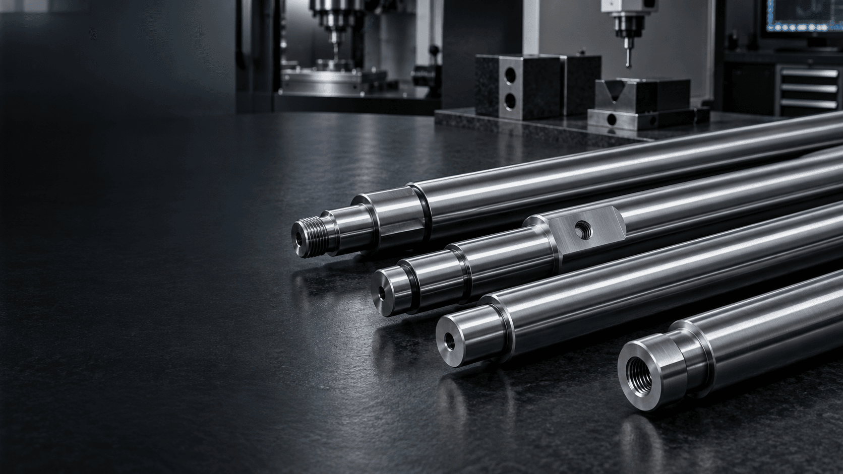
CUSTOM LINEAR MOTION SHAFT MANUFACTURER
Custom Linear
Motion Shafts
Built for smooth, accurate linear travel.
Custom precision linear motion shafts with hardened, ground running surfaces, controlled diameter and straightness for linear bearings, automation and guided-motion systems.We review the bearing interface, load, support arrangement, surface condition and custom end geometry around your drawing.
If available, include the linear bearing manufacturer and model for a more accurate interface review.LINEAR MOTION ENGINEERING SNAPSHOT
The shaft is a guided travel surface—not simply a round bar.
The running diameter, bearing fit and complete axis work together to support predictable linear movement.- Primary function
- Provide a precision cylindrical guide surface for linear bearings and bushings
- Critical geometry
- Running diameter, straightness, roundness, cylindricity and surface roughness
- Bearing interface
- Fit and clearance evaluated around the specified linear bearing
- Surface performance
- Material, hardness, hardened depth and finish selected from the drawing
- Custom geometry
- Threads, holes, grooves, shoulders, flats and mounting ends
- Project review
- Load, stroke, support span, environment and required travel accuracy
WHAT IS A LINEAR MOTION SHAFT?
A precision bearing raceway for controlled translation.
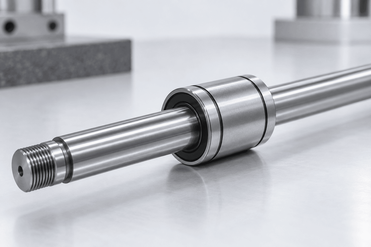
Linear motion shafts are cylindrical guide components used with linear bearings or bushings. The bearing moves along the shaft surface, so diameter consistency, straightness and running-surface condition directly affect travel behavior.
Unlike a general rotating shaft, the key engineering identity is the precision guide surface together with the mounting and end geometry required by the OEM assembly.
GUIDE-SURFACE REQUIREMENTS
What defines a custom linear motion shaft?
Surface hardness
Specified where rolling contact, wear resistance or durability calls for it.Surface roughness
A smooth running surface can reduce friction and support predictable bearing contact.Straightness
Controls the travel path, especially across longer unsupported spans.Custom end machining
Threads, holes, grooves, flats and shoulders integrate the shaft into the machine.Support arrangement
Shaft diameter, length, load and mounting method determine stiffness and deflection.SURFACE—FIT—STRAIGHTNESS WORKFLOW
How are custom linear shafts manufactured?
Manufacturing is planned around the required guide surface and the effect of treatment and end machining on final geometry.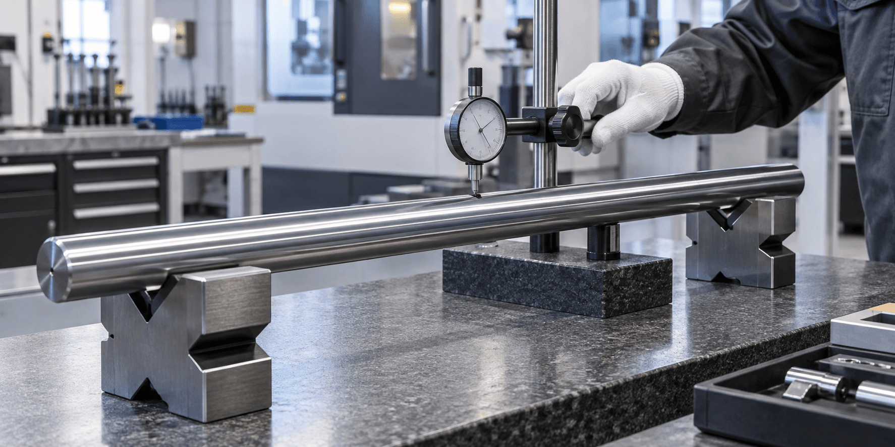
PRECISION RUNNING AXIS
Diameter tolerance and straightness serve different purposes.
Diameter helps establish the intended linear-bearing fit. Straightness defines the travel path. A shaft can meet its diameter requirement but still create poor linear behavior if its axis is not suitable for the application.- Running diameter and diameter consistency along the bearing path
- Roundness, cylindricity and surface roughness
- Straightness and overall length
- Surface hardness and hardened depth where specified
- Thread, hole, groove and mounting-feature locations
FIT AND STIFFNESS
Linear travel depends on the complete installed condition.
The right fit is selected around the actual linear bearing, not a generic tolerance. Support span, load and shaft diameter also matter because an unsupported shaft can deflect under radial or moment loading.Supported vs. unsupported
Long unsupported shafts can require particular attention to stiffness, support locations and expected load. The drawing should make the installed condition clear.
Solid vs. hollow
Hollow construction can reduce mass or add internal routing space, but wall thickness and stiffness must remain suitable for the application.
APPLICATION CONTEXT
Where are linear motion shafts used?
Industrial automation
Guide slides, transfer mechanisms and positioning assemblies.Robotics
Support linear actuators and guided moving elements.Packaging equipment
Enable controlled feed, positioning and moving mechanisms.Measuring equipment
Provide a smooth guide path for inspection and positioning systems.Laboratory equipment
Support compact precision stages and instrument movement.Special-purpose machinery
Custom mounting geometry for drawing-defined machine assemblies.RELATED SHAFT TYPES
Guided travel has a different engineering identity from rotation.
Linear Motion Shaft vs. Roller Shaft
Roller shafts support or drive a rotary roller. Linear motion shafts provide a cylindrical guide surface for translating bearings.Explore →Linear Motion Shaft vs. Spindle Shaft
A spindle is engineered around a precision rotational axis. A linear shaft is engineered around a precision travel surface.Explore →Linear Motion Shaft vs. Hollow Shaft
Hollow describes bore geometry. A linear shaft can be solid or hollow while retaining its guided-motion purpose.Explore →Linear Motion Shaft vs. Stepped Shaft
Stepped shaft describes geometry. Linear motion shaft describes the bearing-guide application and running-surface requirements.Explore →PREPARE YOUR RFQ
What is needed for a linear motion shaft quote?
The linear bearing and operating conditions help us review the shaft interface correctly.- 01Shaft diameter, overall length, solid or hollow construction and stepped sections
- 02Linear bearing manufacturer, model, bore size and required fit or clearance
- 03Stroke, travel speed, radial load, moment load, duty cycle and support span
- 04Material, surface hardness, hardened depth, roughness and straightness
- 05Threads, holes, flats, grooves, shoulders and custom mounting geometry
- 06Quantity, inspection documentation and target delivery requirements
LINEAR MOTION SHAFT FAQS
Common engineering questions.
Practical guidance for automation, motion-control and OEM sourcing teams.What is a linear motion shaft?+
A linear motion shaft is a precision cylindrical guide used with linear bearings or bushings to provide controlled straight-line movement.
Why are linear shafts hardened?+
Where rolling elements run directly on the shaft, surface hardness can help resist rolling-contact wear and permanent deformation. The required condition follows the bearing and application.
Is h6 the standard tolerance for every linear shaft?+
No. The right tolerance depends on the bearing system and the intended clearance or preload. The bearing supplier and drawing should define the required fit.
Why does straightness matter?+
The bearing travels along the shaft geometry. Excessive bow can create binding, varying clearance, additional bearing load and positioning error.
Can custom threads and holes be added?+
Yes. Tapped ends, external threads, cross holes, flats, grooves, steps and mounting features can be produced according to the drawing and process plan.
Can linear motion shafts be hollow?+
Yes. Hollow versions can reduce mass or create internal space, but wall thickness, stiffness, load and support span need to be evaluated together.
READY TO START?