
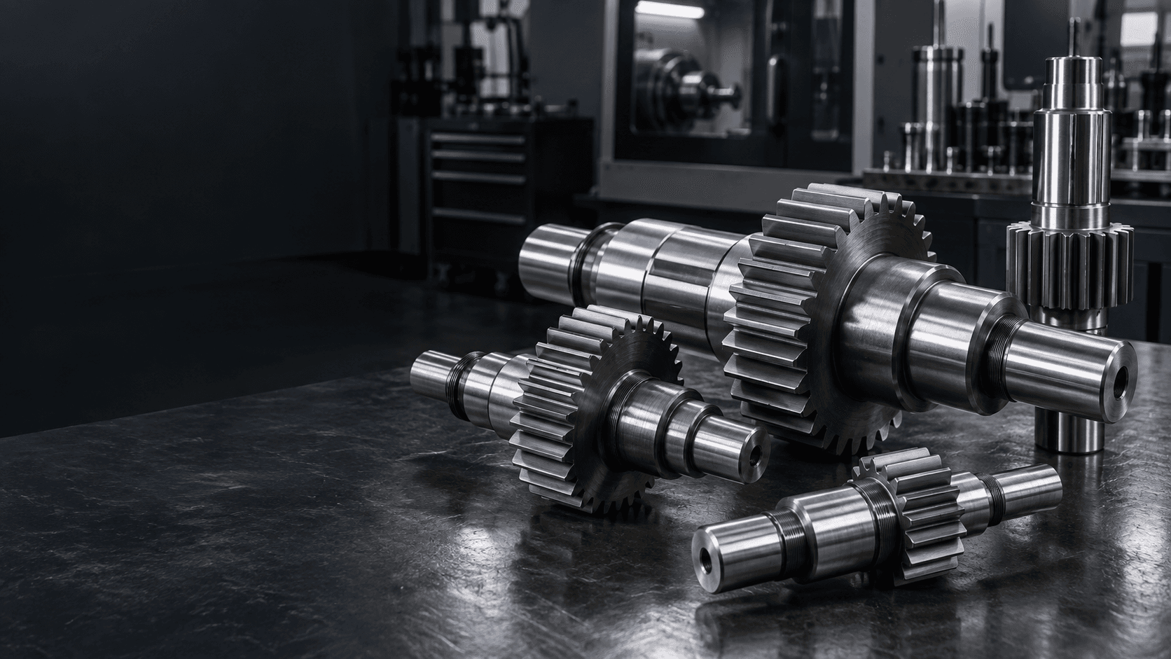
INTEGRAL GEAR SHAFT MANUFACTURING
Custom Gear
Shaft
Gear teeth and shaft geometry built as one component.
Topshaft manufactures custom integral gear shafts and pinion shafts with precision-controlled gear teeth, bearing journals and rotational datums for gearboxes and OEM power transmission systems.Gear geometry, journal fits, gear-to-journal runout, heat treatment and inspection requirements are reviewed around your drawing.
For faster evaluation, include module or DP, pressure angle, tooth count and mating-gear data where available.GEAR SHAFT ENGINEERING SNAPSHOT
Integral gear and shaft geometry, planned together.
Every manufacturing route starts with the function of the gear section and the journals that define its rotational axis.- Component type
- Integral spur gear shafts and pinion shafts
- Gear data
- Module / DP, pressure angle, tooth count and face width
- Critical relationship
- Gear-to-journal runout, coaxiality and shaft straightness
- Manufacturing route
- Turning, gear cutting, heat treatment, grinding and inspection
- Shaft features
- Journals, shoulders, splines, keyways, grooves, threads and holes
- Inspection
- Gear geometry, journal fits, runout and drawing-specific checks
WHAT IS A GEAR SHAFT?
One part that carries both the gear and its operating axis.
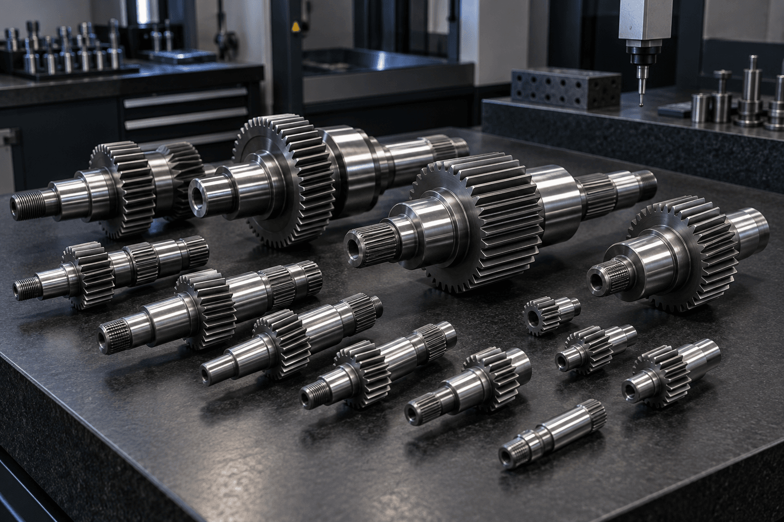
An integral gear shaft combines gear teeth, a shaft body and usually bearing journals, shoulders or transmission interfaces in a single component. It can reduce a separate gear-to-shaft joint and allows the relationship between teeth and journals to be controlled on one workpiece.
A good tooth profile is only part of the job. The gear must also rotate correctly relative to its bearing references and mating gear.
GEAR PARAMETERS
What data defines a custom gear shaft?
Pressure angle
Defines the involute tooth geometry and mesh relationship.Tooth count
Establishes the ratio and pitch diameter with the mating component.Face width
Influences tooth contact area and load distribution.Gear accuracy
Specify the applicable tooth profile, pitch and runout requirement.Rotational datums
Bearing journals define the axis used to evaluate the gear section.INTEGRAL GEAR DESIGN
Why use an integral gear shaft?
The design can simplify assembly and remove a separate joint, but it places more importance on planning the tooth geometry, shaft datums and finishing sequence together.Gear teeth
The torque-transfer feature that meshes with the mating gear.Bearing journals
The surfaces that establish the operating rotational axis.Shoulders & faces
Axial location surfaces for bearings, gears and assemblies.Splines / keyways
Additional torque or assembly interfaces when specified.MANUFACTURING ROUTE
How is a gear shaft manufactured?
The exact process is selected around the drawing, material, required tooth geometry, treatment and critical final surfaces.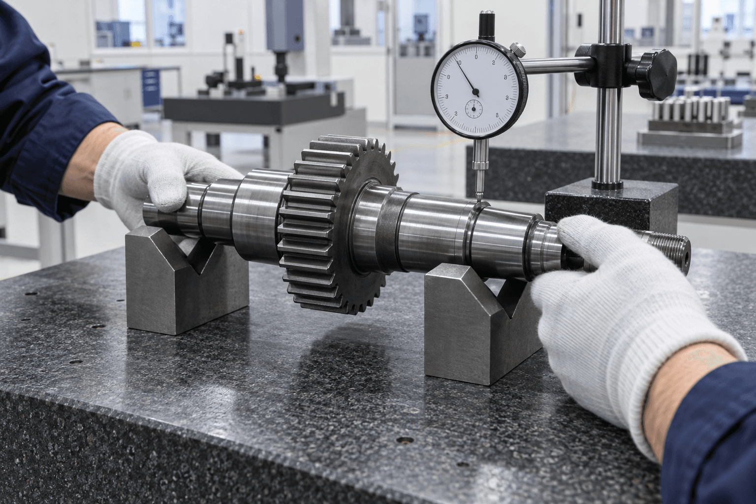
GEAR-TO-JOURNAL ALIGNMENT
Gear accuracy and shaft accuracy must work together.
Tooth profile, pitch and tooth thickness affect meshing. Bearing journal diameters, roundness and coaxiality establish the operating axis. The relationship between those two systems is often decisive.- Gear-to-journal runout and intended datum axis
- Journal diameter, roundness and surface finish
- Gear tooth profile, pitch, thickness and face width
- Shaft straightness, shoulder locations and feature timing
- Hardness and drawing-specific inspection evidence
HEAT TREATMENT AND FINISHING
Plan for stability after heat treatment.
Heat treatment can improve strength and wear performance, but it may also affect geometry. The route can reserve finishing allowance for the features requiring final control.Soft machining
Turning and gear cutting can establish the main form before a specified thermal process.
Hard finishing
Grinding or finishing can be used selectively after treatment where journals or gear surfaces need final refinement.
APPLICATION CONTEXT
Where are integral gear shafts used?
Industrial gearboxes
Power-transfer components between reduction stages.Gear motors
Motor-side pinion shafts for compact first-stage drives.Speed reducers
Integrated geometry for dense transmission layouts.Automation equipment
Repeatable rotary transmission in machinery and actuators.Machine tools
Drive and feed mechanisms with defined rotational relationships.Material handling
Conveyor and handling drivetrain components.Agricultural machinery
Gearbox systems distributing mechanical power.Electric drive systems
Motor-to-reduction-stage torque transfer.GEAR SHAFT VS. RELATED PARTS
Keep the engineering purpose clear.
Gear Shaft vs. Helical Gear Shaft
Gear shaft is the parent category; the dedicated helical page focuses on helix angle, hand and axial thrust.Explore →Gear Shaft vs. Transmission Shaft
A gear shaft has integral teeth. A transmission shaft transfers power and may instead carry a separate gear.Explore →Gear Shaft vs. Spline Shaft
Gear teeth mesh to create a ratio. Splines engage an internal mating spline for coaxial torque transfer.Explore →Pinion Shaft
The smaller member of a gear pair, often manufactured with the shaft as one component.Explore →PREPARE YOUR RFQ
What is needed for a gear shaft quote?
Complete gear and shaft data helps us evaluate the most appropriate manufacturing and inspection route.- 01Module or DP and pressure angle
- 02Tooth count and face width
- 03Gear type and accuracy requirement
- 04Mating gear information where available
- 05Bearing journals, datums and runout
- 06Features: splines, keyways, threads, holes
- 07Material, heat treatment and hardness
- 08Prototype and production quantities
BUYER QUESTIONS
Gear shaft FAQs
Practical answers for gearbox and industrial sourcing projects.What is a gear shaft?+
A gear shaft has gear teeth integrated directly into the shaft body, so the gear and shaft operate as one functional power-transmission component.
What is a pinion shaft?+
A pinion shaft is typically an integral shaft containing the smaller gear member in a mating gear pair.
Why does gear-to-journal runout matter?+
Bearing journals define the operating axis. If the gear is eccentric to that axis, gear meshing and load distribution can be affected.
Can gear shafts be heat treated?+
Yes. The appropriate route depends on the material and drawing; it may include carburizing, induction hardening, quenching and tempering, nitriding or another specified treatment.
What is the difference between a gear shaft and a helical gear shaft?+
Gear shaft is the broader parent category. A helical gear shaft specifically has angled teeth and additional helix-angle and helix-hand requirements.
What information is needed for a quote?+
Please share the drawing, module or DP, pressure angle, tooth count, face width, gear accuracy, journal tolerances, material, heat treatment and quantity.
READY TO START?