
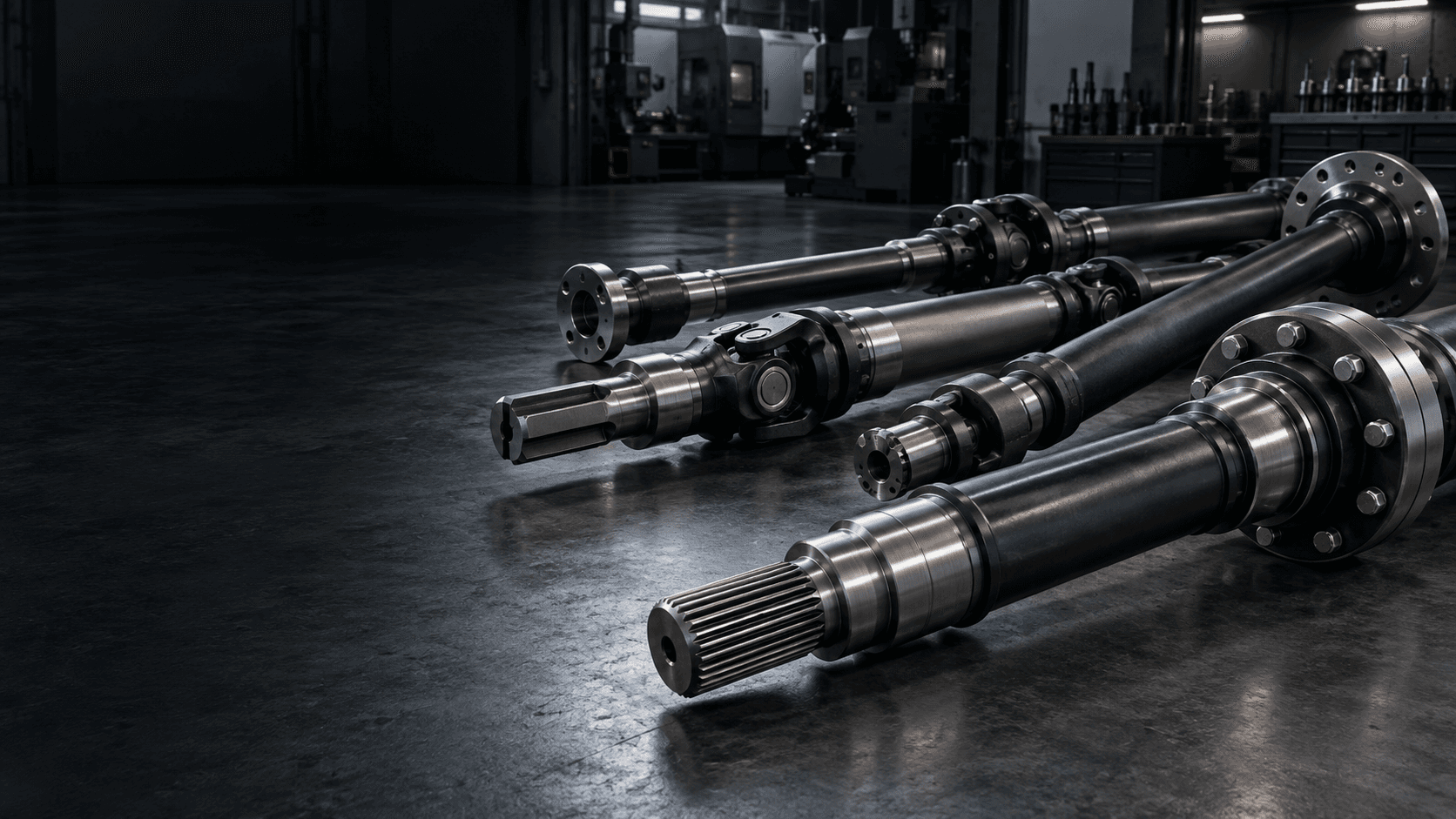
CUSTOM INDUSTRIAL DRIVE SHAFT MANUFACTURER
Custom Drive
Shaft
Transfer torque reliably from one component to the next.
Custom industrial drive shafts engineered around torque transfer, shaft length, rotational speed and precision end connections for OEM machinery and power-transmission systems.We review both end interfaces, material, operating RPM, runout and inspection requirements around your drawing.
For long or high-speed shafts, include maximum RPM and balance requirements whenever available.DRIVE SHAFT ENGINEERING SNAPSHOT
Design the complete torque path—not only the shaft body.
End connections, length, stiffness and rotational behavior need to work together.- Core function
- Transfer torque between separate driving and driven components
- End connections
- Splines, keys, coupling seats, flanges, threads and custom interfaces
- Operating data
- Torque, peak torque, RPM, shaft length and duty cycle
- Critical geometry
- Runout, straightness, end-to-end coaxiality and fit surfaces
- Manufacturing
- CNC turning, milling, spline machining, heat treatment and grinding
- Project review
- Balance and critical-speed requirements when specified
WHAT IS A DRIVE SHAFT?
A torque-transfer link between two mechanical systems.
A drive shaft transfers rotary power between a driving component and driven equipment. It can connect motors, couplings, gearboxes, pumps, conveyors and other industrial equipment across an installed distance.
The important engineering questions are where torque enters and exits, how the shaft is supported, how much torque and speed it sees, and what each end interface must locate or engage.
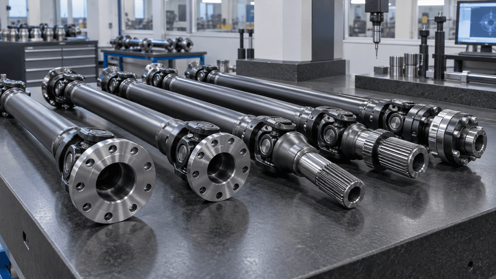
TORQUE PATH AND CONNECTIONS
What defines a custom drive shaft?
Shaft body
Solid or hollow geometry selected around torque, stiffness, weight and installed length.Driven end
Spline, key, flange, taper or coupling interface delivering torque onward.Operating speed
RPM, runout and mass distribution influence vibration behavior.Installed length
Longer shafts require attention to stiffness, straightness and dynamic behavior.Functional datums
Journals and seats establish the rotational references for the assembly.MANUFACTURING ROUTE
How are custom drive shafts manufactured?
The route is selected around the connection system, operating envelope and precision requirements.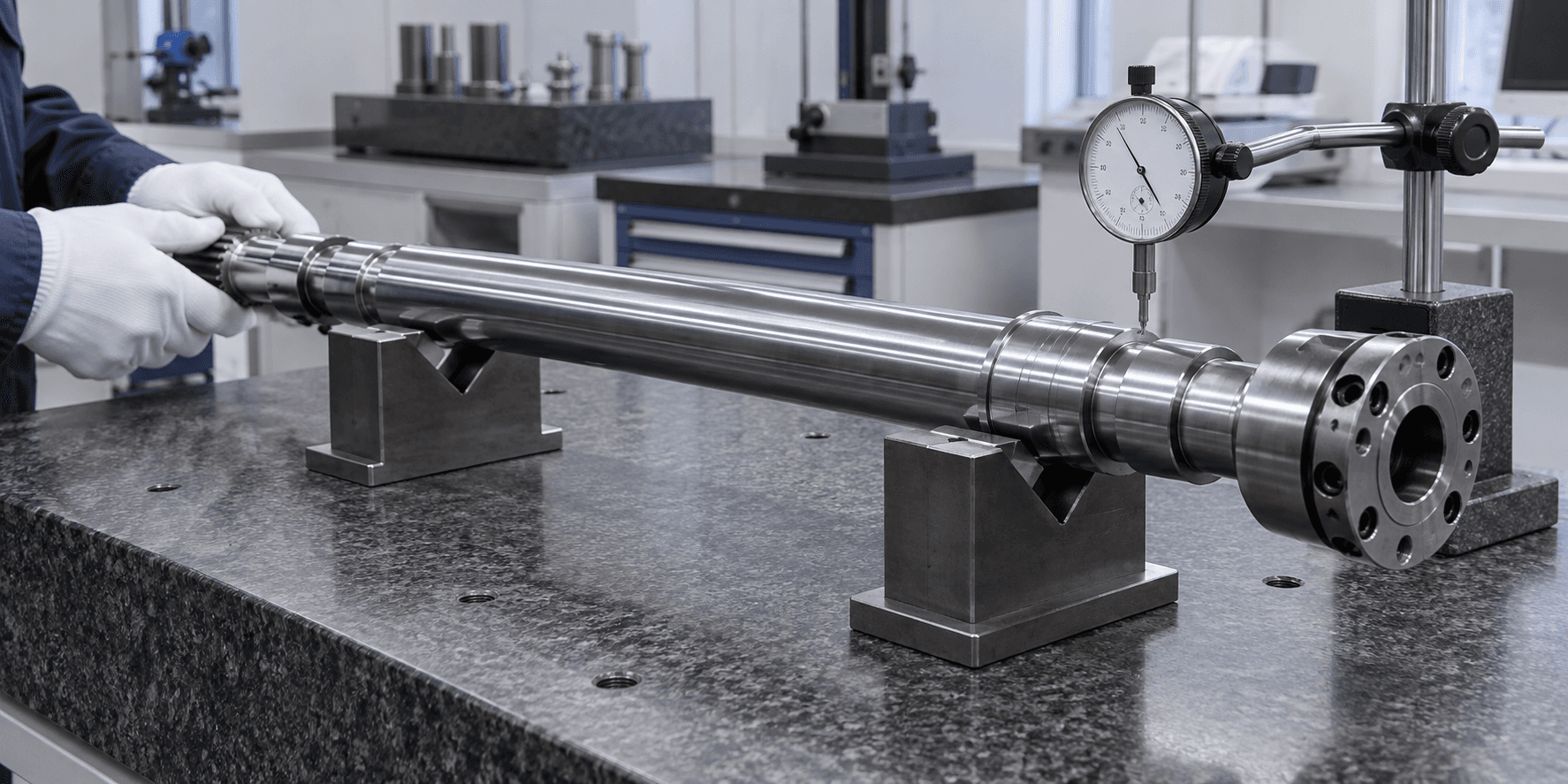
ROTATIONAL GEOMETRY
Runout and balance solve different problems.
Runout is geometric variation relative to the intended rotational datum. Balance concerns mass distribution around that axis. Both may matter, particularly as length and RPM increase.- Shaft diameter, installed length and straightness
- End-to-end coaxiality and coupling-seat fits
- Spline geometry, keyway position and flange-face runout
- Critical surface roughness and heat-treatment requirements
- Balance or critical-speed requirements when specified
HIGH TORQUE OR HIGH SPEED
Different operating conditions create different priorities.
High torque can shift attention toward strength, torsional stiffness, fatigue and connection capacity. Higher speed can add runout, straightness, mass distribution, vibration and critical-speed considerations.Solid vs. hollow
Hollow construction can reduce rotating mass, but OD, ID, wall thickness, torque and stiffness must be evaluated together.
Drive vs. transmission
A drive shaft connects separate components. A transmission shaft is often part of an internal gearbox or machine power-transmission mechanism.
APPLICATION CONTEXT
Where are custom drive shafts used?
Industrial machinery
Connect motors, gearboxes and driven equipment.Automation equipment
Transfer rotary power between machine stations.Pumps & compressors
Link drive motors, couplings and rotating equipment.Agricultural machinery
Transmit torque through attachments and mechanical drives.Material handling
Drive conveyors, rollers and processing systems.Construction equipment
Heavy-duty custom power-transfer components.Gearbox systems
Connect gearbox output to downstream equipment.Special-purpose machinery
Drawing-specific shaft and connection layouts.RELATED PRODUCTS
Separate function from connection geometry.
Drive Shaft vs. Spline Shaft
Drive shaft defines the torque-transfer role; splines are one possible end-interface geometry.Explore →Drive Shaft vs. Transmission Shaft
Drive shafts link components across a distance; transmission shafts commonly serve internal power transmission.Explore →Drive Shaft vs. Hollow Shaft
A hollow shaft describes bore geometry; a hollow drive shaft can still be a torque-transfer component.Explore →Drive Shaft vs. Gear Shaft
A gear shaft has integral gear teeth; a drive shaft may have splined, keyed or flanged ends instead.Explore →PREPARE YOUR RFQ
What is needed for a drive shaft quote?
Complete connection, operating and geometry data helps us review the correct route.- 01Overall length, maximum diameter and solid or hollow construction
- 02Spline, keyway, coupling, thread, flange or custom end data
- 03Continuous torque, peak torque and operating RPM
- 04Duty cycle, rotation direction and axial movement where applicable
- 05Runout, straightness, fit surfaces and GD&T
- 06Material, treatment, hardness and surface protection
- 07Balance requirement, if specified
- 08Quantity and inspection documentation
READY TO START?