Build displacement
The lobe moves the follower through the required stroke across a defined angular interval.

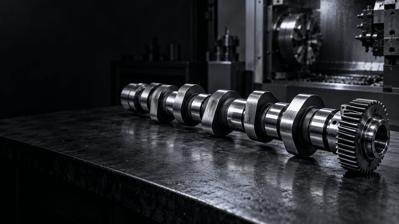
CUSTOM CAMSHAFT MANUFACTURER
Topshaft manufactures drawing-based OEM camshafts for engine, automation and special-machine applications—built around your profile data, journal geometry and inspection requirements.
For a unique motion profile, include complete lobe or motion data whenever available.ENGINEERING SNAPSHOT
A camshaft needs both profile accuracy and conventional shaft accuracy. Lobe geometry, phase, journals and functional surfaces are reviewed as one complete component.
CAMSHAFT FUNDAMENTALS
A camshaft converts continuous rotation into programmed follower motion. Unlike a standard shaft, its functional performance is determined by the geometry of each lobe and the exact angular relationship between those lobes.
Maximum lift alone is not enough to define performance. The base circle, flank, nose, rise, dwell, return and lobe phase can all shape motion, contact load and timing.
MOTION & TIMING
The lobe moves the follower through the required stroke across a defined angular interval.
The follower remains at a required position while the cam continues to rotate.
The profile guides the follower back without treating the motion as a simple circular eccentric.
Each lobe's angular position must stay controlled relative to the selected rotational datum.
APPLICATION CONTEXT
Both use lobe geometry to control movement, but the engineering inputs are different. We manufacture from the requirements that define your actual application.
WEAR & FINISH CONTROL
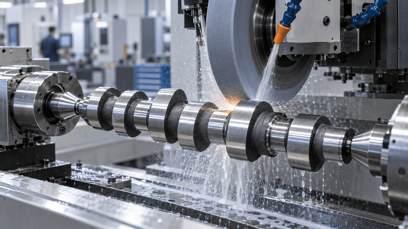
Rough machining can remove material efficiently, but final lobe geometry may require controlled profile form, a smooth transition between profile regions and a specified finish on hardened material.
Depending on the drawing, the manufacturing route can combine turning, profile machining, heat treatment, journal grinding, cam lobe grinding and inspection.
MANUFACTURING ROUTE
Review the drawing, CAD model or complete lobe-profile data with its rotational datum and angular positions.
Select the specified billet, forging or blank with allowance for heat treatment and final grinding.
Machine journals, shoulders, end diameters, grooves and drive interfaces around the intended axis.
Create the lobe form with material allowance retained where final grinding is specified.
Apply the agreed heat-treatment route, then finish critical journals and lobe surfaces.
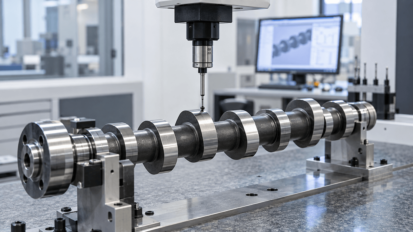
Verify profile, lift, angular relationship, journal dimensions, runout, straightness and specified hardness.
PROFILE INSPECTION
Profile measurement must distinguish true lobe-form deviation from shaft eccentricity or datum error. The control plan can therefore check the cam profile alongside journal, runout and straightness characteristics.
RELATED SHAFT TYPES
A camshaft controls motion through the shape of one or more non-circular lobe profiles. An eccentric shaft produces motion primarily by offsetting a journal or axis from the main rotational centreline.
Programmed follower motion through profile shape, including rise, dwell, return and controlled lobe phase.
Orbital or reciprocating motion driven mainly by eccentric offset rather than a complex cam profile.
Explore custom eccentric shafts →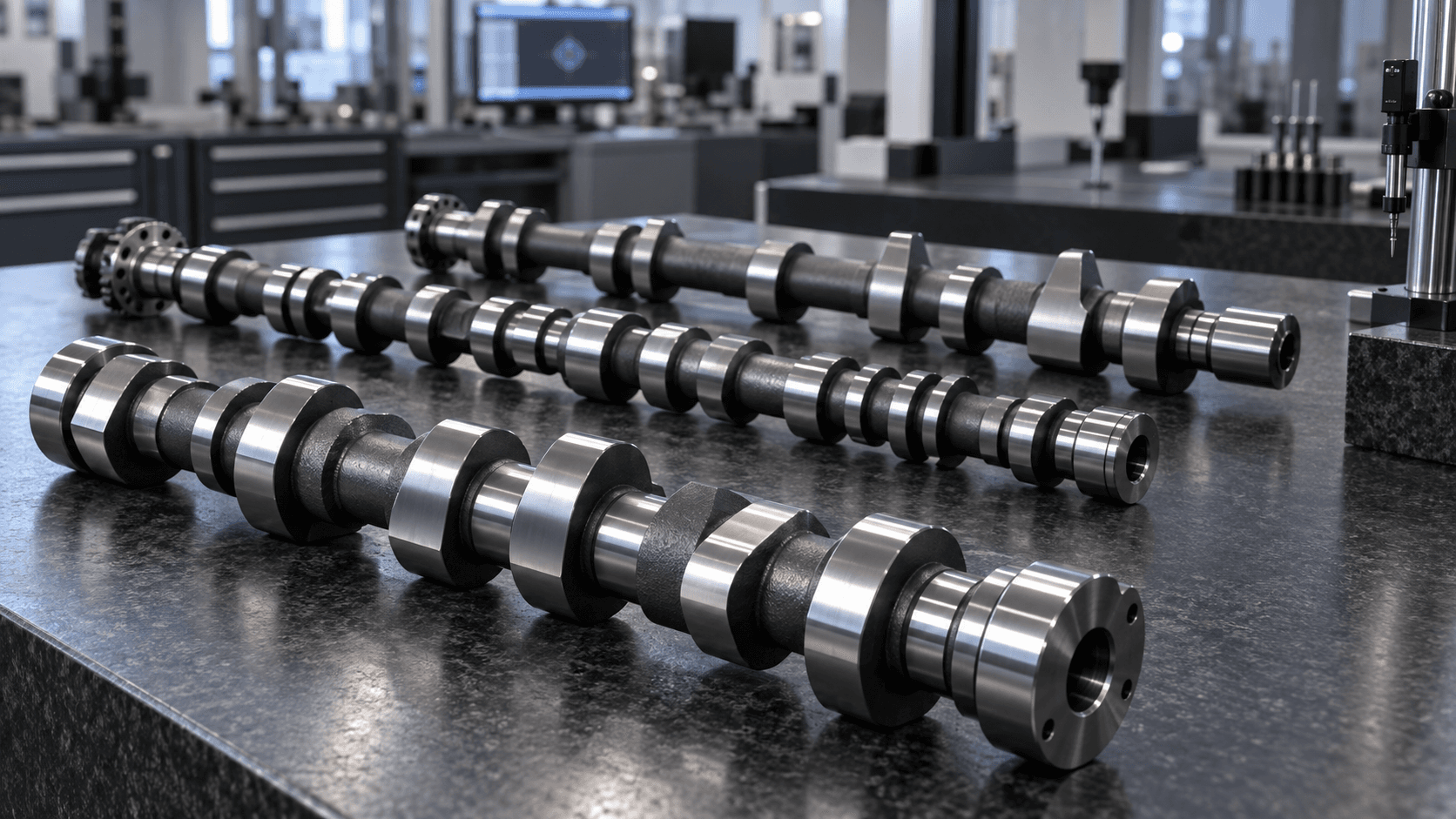
DRAWING-BASED OEM SUPPLY
Custom camshaft projects may begin with replacement, prototype or new-machine geometry. We support drawing-led manufacturing for validation batches and repeat production where the profile, materials and inspection requirements are defined.
Discuss Your Camshaft Project →PREPARE YOUR RFQ
BUYER QUESTIONS
A camshaft is a rotating shaft with one or more shaped lobes. As each lobe rotates, it produces controlled follower motion. In engines this controls valve timing; in industrial machinery it can create programmed mechanical movement.
A cam lobe is the non-circular portion of the shaft. Its profile determines the follower displacement as the shaft turns.
Two lobes can have the same maximum lift but create very different motion. Base circle, rise and return shape, dwell, angular timing and contact conditions all affect function.
Yes. We manufacture to customer-supplied drawings, CAD geometry and complete profile specifications. For unique motion requirements, provide the full profile or motion data rather than only maximum lift.
Lobes work under repeated contact. A specified material and treatment route can improve wear resistance, while grinding can establish the final profile and surface finish.
Provide a 2D drawing, 3D CAD model, lobe profile data, journal and end-feature details, material, treatment, quantity and inspection requirements.
READY TO START?