
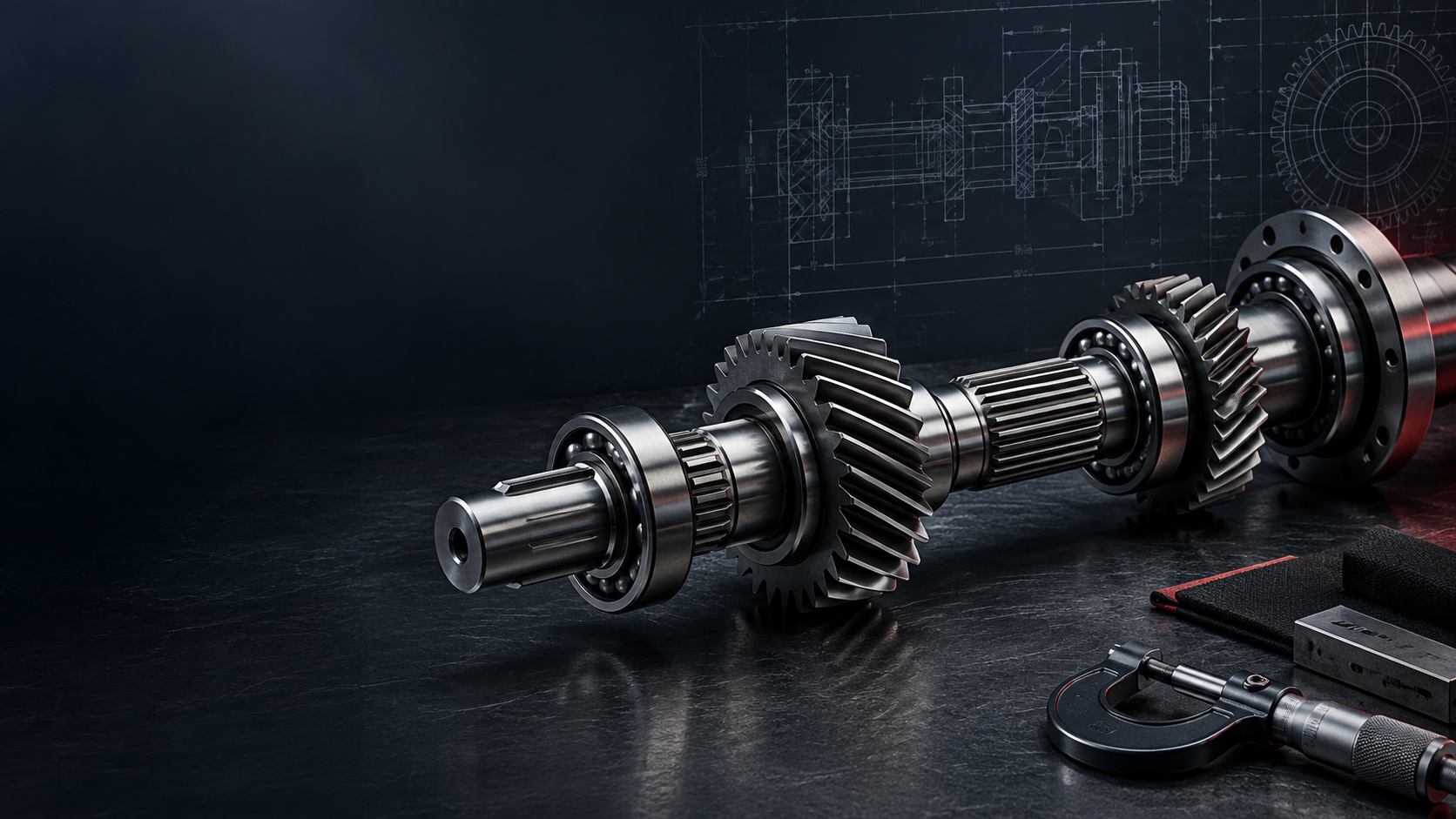
CUSTOM GEARBOX SHAFT MANUFACTURER
Gearbox Precision,
Designed For Transfer.
Precision input, intermediate, gear, spline and output shafts manufactured around bearing alignment, torque-transfer interfaces, heat treatment and gearbox-specific dimensional requirements.INPUT / INTERMEDIATE / GEAR / SPLINE / OUTPUTGEARBOX SHAFT ENGINEERING SNAPSHOT
Built For The Shaft's
Position In The Gearbox.
Topshaft manufactures custom precision shafts for industrial gearboxes, speed reducers and power-transmission systems. The review follows the path of torque through the gearbox, with attention to bearing fits, gear and spline interfaces, runout, alignment, heat treatment and ground functional surfaces.| Capability | TOPSHAFT support |
|---|---|
| Manufacturing type | Custom / OEM / made to drawing |
| Gearbox shaft roles | Input, intermediate, countershaft, output, gear, pinion, spline and worm shafts |
| Machining | CNC turning, milling, gear and spline machining, grinding and finishing |
| Materials | Carbon, alloy, carburizing and selected stainless steels |
| Heat treatment | Q&T, carburizing, induction hardening, nitriding and drawing-specified routes |
| Critical controls | Bearing fits, runout, coaxiality, straightness, gear/spline interfaces, hardness and surface finish |
| Production | Prototype, first article, pilot batch and repeat OEM production |
| Inspection | Dimensional, geometric, surface and drawing-specific inspection |
HOW TORQUE MOVES THROUGH A GEARBOX
Input To Output,
One Controlled Path.
The industry page connects gearbox shaft roles at system level; the linked product pages provide deeper detail about each individual shaft technology.Motor / Engine ↓ Input Shaft ↓ Gear Stage 1 ↓ Intermediate / Countershaft ↓ Gear Stage 2 ↓ Output Shaft ↓ Driven Equipment
Gearbox shaft manufacturing is functional geometry.
Torque transmission is only one part of the job. The shaft must also rotate correctly between bearing supports while carrying gears, splines, retaining features and defined journal surfaces.
Gearbox shaft manufacturing is not only about accurate features—it is about controlling the relationships between those features.
PRECISION SHAFT SOLUTIONS FOR GEARBOX SYSTEMS
Each Shaft Has A
Different System Role.
Input, intermediate and output functions create different loads, interfaces and datum relationships. The right manufacturing route starts with that operating role.GEARBOX SHAFT APPLICATIONS AT A GLANCE
Architecture Changes
The Shaft Requirement.
| Gearbox position | Typical shaft components | Common critical requirements |
|---|---|---|
| Input stage | Input shaft, spline shaft, pinion shaft | Coupling interface, bearing fits, torque, runout |
| Intermediate stage | Countershaft, gear shaft, spline shaft | Gear-to-journal alignment, bending, fatigue |
| Output stage | Output shaft, drive shaft, stepped shaft | Torque interface, straightness, retained-component location |
| Helical reducer | Helical gear shaft, input/output shaft | Axial force, gear accuracy, bearing support |
| Worm reducer | Worm shaft, output shaft | Worm profile, thrust, sliding contact, bearing alignment |
| Planetary gearbox | Input, sun gear, output shaft, spline interface | Concentricity, functional fits, torque path |
| Servo / precision reducer | Precision gear, spline and output shafts | Runout, backlash-sensitive geometry, bearing alignment |
| Heavy industrial gearbox | Large input, gear and output shafts | Torque, fatigue, heat-treated alloy steel, large journals |
WHAT MAKES A GEARBOX SHAFT DIFFERENT?
Torque And Bending
Meet One Axis.
- 01Multiple bearing supportsJournal relationship can matter more than any one nominal diameter.
- 02Gear alignmentA gear seat or integral gear must rotate around the bearing-defined shaft axis.
- 03Axial loadsHelical and worm gearing can create axial force managed by the bearing system.
- 04Torque interfacesOutput and intermediate shafts can combine splines, keys, couplings and threaded retention.
- 05Wear-critical surfacesGear teeth, spline flanks and bearing surfaces may need treatment, grinding or defined finish.
- 06Functional axisGear and spline geometry must be evaluated in relation to the bearing-defined axis.
WHY GEAR-TO-BEARING ALIGNMENT MATTERS
Bearings Define
The Real Axis.
A gearbox shaft contains gear or spline geometry plus bearing journals. If the gear or spline is misaligned relative to this bearing-defined axis, the assembly can experience uneven tooth engagement, varying backlash, vibration, noise and localized wear.- Gear / spline geometry and bearing journals should share the required rotational relationship
- Gear-to-journal runout can matter as much as individual diameter tolerance
- Functional datums should follow how the shaft is supported and assembled
- Final inspection needs to reflect the drawing-defined critical relationships
CRITICAL GEARBOX SHAFT CHARACTERISTICS
Measure The Features
That Control The Mesh.
The drawing defines the final CTQs. These are the typical technical controls that affect bearing support, torque transfer, gear mesh and axial location.Discuss Your Gearbox Project →| CTQ | Gearbox function |
|---|---|
| Bearing Journal Diameter | Controls bearing fit |
| Journal Roundness | Supports smooth rotation |
| Journal Coaxiality | Defines the shaft rotational axis |
| Shaft Straightness | Maintains alignment across the gearbox |
| Gear-to-Journal Runout | Supports consistent gear mesh |
| Gear Seat Diameter | Controls mounted gear fit |
| Spline Fit | Controls torque transfer |
| Shoulder Position | Controls axial location |
| Thread Geometry | Controls bearing-nut and retention interfaces |
| Surface Roughness | Important for bearings and seals |
| Hardness | Supports wear and fatigue requirements |
| Case Depth | Important for hardened gears and splines |
GEARBOX SHAFT SOLUTIONS BY GEARBOX TYPE
Match The Shaft To
The Architecture.
Helical Gearboxes
Helical gear shafts, input shafts, output shafts and spline shafts. Focus: axial gear forces, bearing support and gear accuracy.
Spur Gearboxes
Spur gear shafts, pinion shafts, stepped shafts and output shafts. Focus: gear-to-journal alignment and torque transfer.
Worm Gearboxes
Worm shafts, output shafts and stepped shafts. Focus: worm profile, thrust, sliding contact and bearing alignment.
Planetary Gearboxes
Input shafts, sun gear shafts, output shafts and spline interfaces. The page does not claim complete planetary gearsets or carriers.
Servo & Precision Reducers
Runout, backlash-sensitive geometry, bearing alignment and precision spline or gear interfaces.
Heavy-Duty Industrial Gearboxes
Mining, conveyors, cranes, steel machinery and processing equipment. Focus: torque, fatigue, alloy steel and large journals.
MATERIALS & HEAT TREATMENT
Choose Material For
The Working Surface.
The material choice follows torque, fatigue, wear, heat treatment and environment requirements. A treatment route should be defined with the selected material and the actual functional surface in mind.| Material | Typical use | Why it is selected |
|---|---|---|
| 1045 / C45 | General gearbox shafts | Strength, machinability and cost |
| 4140 / 42CrMo | Input, output and transmission shafts | Strength, toughness and heat-treatment response |
| 4340 | High-load shafts | High strength and fatigue resistance |
| 8620 / similar carburizing steels | Gear and spline shafts | Hard case with a tougher core |
| 20CrMnTi | Gearbox gear shafts | Carburizing response and wear resistance |
| 17-4PH stainless | Specialized gearbox shafts | Strength plus corrosion resistance |
| 304 / 316 stainless | Corrosive environments | Corrosion resistance |
Quenching & Tempering
Strength, toughness and fatigue resistance for suitable input, output and transmission shafts.
Carburizing
Particularly relevant for gear teeth, spline teeth and pinion shafts: a hard case with a tougher core.
Induction Hardening
Selective hardening of journals, splines and specified gear-related surfaces.
Nitriding
Wear-resistant surfaces on compatible steels where specified.
Post-Heat-Treatment Grinding
Critical bearing journals and gear-related surfaces may require final grinding after treatment where specified.
GEARBOX SHAFT MANUFACTURING CAPABILITIES
Build Each Feature
In The Right Route.
Process planning joins rough machining, torque features, treatment and final finishing around the drawing-defined shaft axis.CNC Turning
Bearing journals, gear blanks, shoulders, grooves and threads.
CNC Milling
Keyways, flats, holes and specialized interfaces.
Gear Machining
Spur gear shafts, helical gear shafts and pinion shafts.
Spline Machining
Input, output and fixed or sliding torque-transfer connections.
Precision Grinding
Bearing seats, seal journals, hardened diameters and selected gear or spline features.
Heat Treatment & Finishing
Integrated around the drawing and specified final mechanical properties.
FROM GEARBOX DRAWING TO FINISHED SHAFT
Plan The Route
Before The Part.
The manufacturing story follows the relationships that the gearbox will use in service, not only a generic sequence of machine operations.- 01Gearbox Shaft ReviewPlanned around the drawing and confirmed project requirements.
- 02Identify CTQs & DatumsConfirm bearing, gear, spline and axial-reference requirements.
- 03Process PlanningPlanned around the drawing and confirmed project requirements.
- 04Rough Shaft MachiningPlanned around the drawing and confirmed project requirements.
- 05Gear / Spline FeaturesPlanned around the drawing and confirmed project requirements.
- 06Heat TreatmentPlanned around the drawing and confirmed project requirements.
- 07Precision GrindingPlanned around the drawing and confirmed project requirements.
- 08Final Gearbox-Shaft InspectionVerify drawing-defined geometry, surface and treatment requirements.
- 09Documentation & DeliveryPlanned around the drawing and confirmed project requirements.
Drawing review → Process planning → Machining → Gear / spline features → Treatment → Grinding → Final inspection
FROM DEVELOPMENT TO REPEAT MANUFACTURING
Prototype To
Production.
Gearbox development commonly progresses through controlled stages rather than directly into recurring production.Project stages
- Prototype: Confirm basic geometry and assembly
- First Article: Validate CTQs and inspection method
- Pilot Batch: Confirm process repeatability
- Production: Maintain agreed shaft requirements
GEARBOX SHAFT QUALITY CONTROL
Inspect Against
The Functional Datums.
Quality requirements are confirmed project by project during quotation and supplier qualification.Inspection may include
- Journal diameters, gear seats, spline dimensions and shoulder position
- Runout, coaxiality, straightness and defined surface roughness
- Hardness and case depth where required
- Agreed dimensional reports, first-article records and material / treatment documentation
DFM CONSIDERATIONS FOR GEARBOX SHAFTS
Make The Drawing
Support Performance.
Clear functional requirements improve manufacturability, cost and production stability.Useful engineering inputs
- Define bearing fits and functional datums around the real shaft-support geometry
- Specify gear and spline geometry completely: module / DP, pressure angle, tooth count, helix angle, standard and fit
- Identify gear-to-journal controls, material, treatment, hardness and case depth
- Identify post-treatment grinding and mating gear, bearing or spline data where useful
WHY TOPSHAFT FOR GEARBOX SHAFTS
Shaft-Focused,
Drawing-Led.
Gearbox projects can bring turning, milling, gear/spline machining, heat treatment, grinding and finishing into one route.Project approach
- Review functional relationships including bearing-to-bearing alignment, gear-to-journal runout and spline interfaces
- Support prototypes, engineering samples, validation quantities and repeat manufacturing
- Manufacture and inspect to the approved drawing and agreed quality requirements
- Use individual product pages for deeper shaft-specific engineering details
WHAT INFORMATION IS NEEDED FOR A GEARBOX SHAFT QUOTE?
Send The Data That
Defines The Torque Path.
Complete shaft, gear, spline, operating and quality data allows a more useful drawing and process review before quotation.Upload Your Gearbox Shaft Drawing →| Information group | Include where available |
|---|---|
| Shaft geometry | Overall length, journals, shoulders, threads, grooves and bores |
| Gear / spline geometry | Gear type, module / DP, pressure angle, tooth count, helix angle, spline standard and fit |
| Precision requirements | Bearing fits, runout, straightness, coaxiality, roughness, GD&T and gear accuracy |
| Material / treatment | Grade, heat treatment, hardness, case depth and surface treatment |
| Operating / commercial data | Gearbox type, input/output RPM, torque, duty cycle, prototype / production quantity, annual volume and documentation |
RELATED GEARBOX SHAFT SOLUTIONS
Follow The Function,
Then Open The Product.
01Transmission ShaftInput, intermediate and output stages→02Gear ShaftIntegral pinions and gear interfaces→03Helical Gear ShaftHelical reducers and axial-load applications→04Spline ShaftShaft-to-hub torque transfer→05Worm ShaftWorm reducers and right-angle drives→06Stepped ShaftMultiple bearing, gear and seal locations→07Hollow ShaftThrough-bore or weight-conscious designs→08Drive ShaftOutput connection to driven equipment→
View All Precision Shaft Products →GEARBOX SHAFT FAQS
Answers For The
Drawing Review.
Practical gearbox questions for engineering and sourcing teams.What types of gearbox shafts can TOPSHAFT manufacture?+
Custom input, intermediate, countershaft, output, gear, pinion, spline, worm, stepped and other made-to-drawing gearbox shaft components can be evaluated.
What is the difference between an input shaft and an output shaft?+
An input shaft receives torque into the gearbox. An output shaft delivers torque from the gearbox to the driven equipment. Their interfaces, loads and critical requirements can differ.
What is an intermediate or countershaft?+
It transfers power between gearbox stages and can carry several gears, bearing journals or spline features on one rotating axis.
What materials are used for gearbox shafts?+
The material follows load, fatigue, wear, treatment and environment requirements. Typical choices include carbon, alloy, carburizing and selected stainless steels.
Why are gearbox shafts heat treated?+
Specified heat treatment can support strength, toughness, fatigue resistance or wear resistance on gear, spline and bearing-related surfaces.
Why is gear-to-journal runout important?+
Bearings define how the shaft rotates. Misalignment between a gear or spline and that bearing-defined axis can contribute to uneven mesh, backlash variation, vibration, noise and localized wear.
Can TOPSHAFT manufacture gearbox gear and pinion shafts?+
Projects can be reviewed from the supplied tooth geometry, bearing journals, material, treatment and inspection requirements.
Can TOPSHAFT manufacture splined gearbox shafts?+
Yes. Complete spline designation, fit, mating function, surrounding journals and drawing requirements should be supplied for review.
Can TOPSHAFT manufacture worm gearbox shafts?+
Worm shaft projects can be evaluated from the complete worm geometry, starts, lead, hand, material, treatment and mating-wheel requirements.
Can bearing journals be ground after heat treatment?+
Where specified, final grinding can control critical bearing fits and the rotational axis after heat treatment.
Can you support gearbox shaft prototypes?+
Projects can start with prototype, first-article or pilot quantities before progressing to repeat manufacturing.
What information is needed for a gearbox shaft quotation?+
Provide the drawing or 3D model, shaft and gear/spline geometry, material, treatment, CTQs, gearbox application, RPM, torque, quantity and documentation requirements.
NEED A CUSTOM GEARBOX SHAFT?