
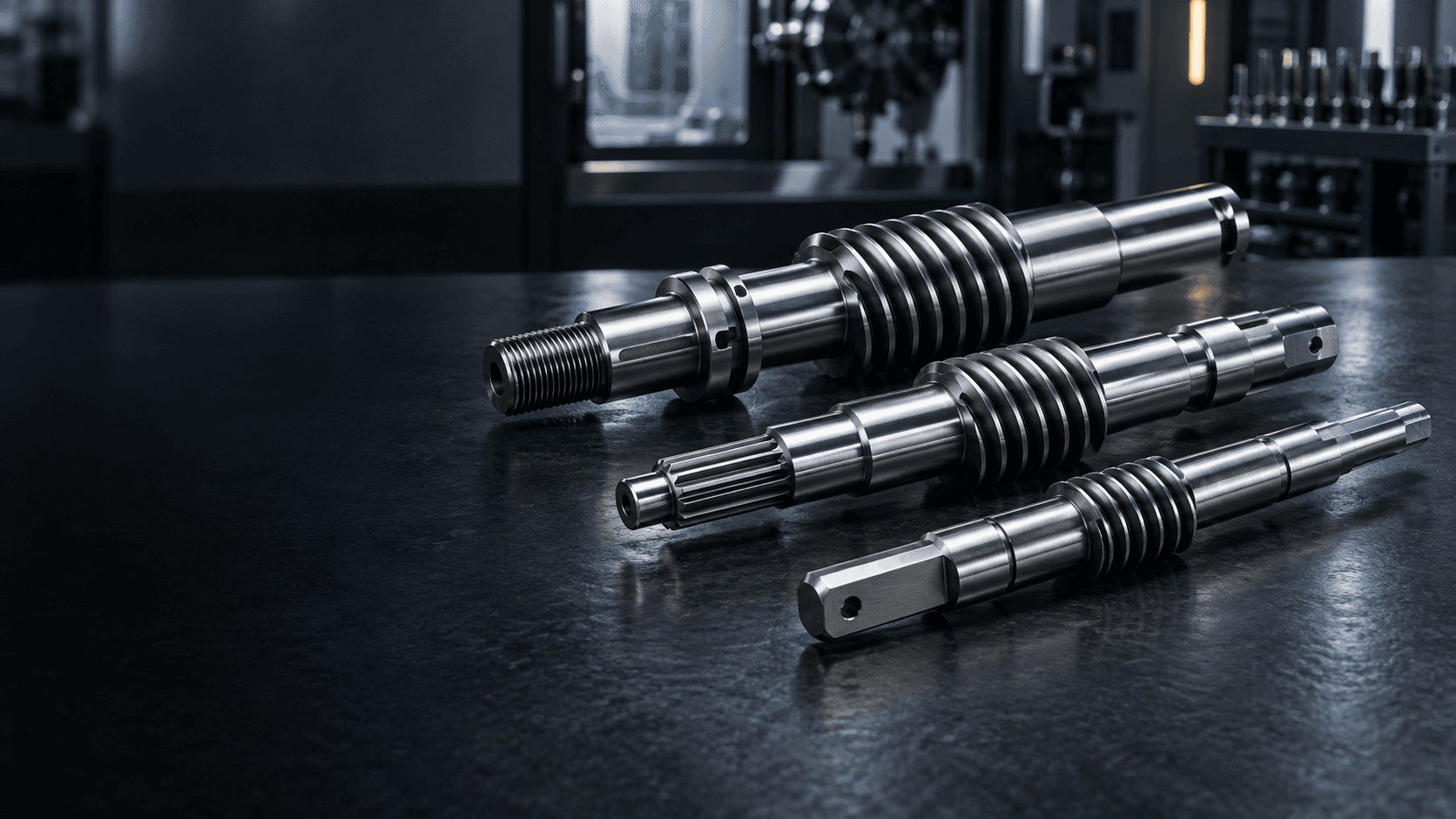
CUSTOM WORM SHAFT MANUFACTURER
Custom Worm
Shafts
Precision worm geometry for compact power transmission.
Custom worm shafts and worm gear shafts for gearboxes, reducers, actuators, automation systems and industrial power-transmission equipment.We review the worm profile, starts, lead, lead angle, hand, bearing alignment, heat treatment and mating-wheel requirements around your drawing.
For faster review, include the worm profile, starts, hand, mating wheel data, material and quantity.WORM SHAFT ENGINEERING SNAPSHOT
A gear mesh and a precision shaft in one component.
Worm performance depends on profile geometry and the way that geometry is held relative to the operating bearing axis.- Worm type
- Cylindrical worm or drawing-defined profile geometry
- Starts & hand
- Single, double or multi-start; right-hand or left-hand helix
- Gear geometry
- Module or pitch, pressure angle, lead, lead angle and reference diameter
- Gear pair
- Mating worm-wheel data, center distance, shaft angle and backlash requirements
- Shaft interfaces
- Bearing journals, shoulders, threads, keyways, splines, grooves and drive ends
- Critical control
- Worm profile, lead, runout, journal alignment, hardness and surface condition
WHAT IS A WORM SHAFT?
A screw-like gear profile built to drive a worm wheel.
A worm shaft combines a precision rotating shaft with a helical gear profile designed to mesh with a mating worm wheel. It is a gear-transmission component, not an ordinary threaded shaft.
Its functional geometry includes the worm profile, starts, lead, lead angle, hand and the relationship between the worm section and bearing journals. The complete pair also depends on the wheel, center distance and assembled backlash.
WORM GEOMETRY
A diameter alone cannot define a worm.
Module or pitch
The scale of the gear system, identified with its correct reference system.Lead and lead angle
Key helix values governing the relationship between the worm and wheel.Pressure angle & profile
Flank geometry must follow the approved standard, profile designation or drawing.Hand
Right-hand or left-hand helix determines the correct mating arrangement.Reference diameter
A core geometry value used to define the worm working form.TECHNICAL VISUAL GUIDE
Understand the worm as a complete gear system.
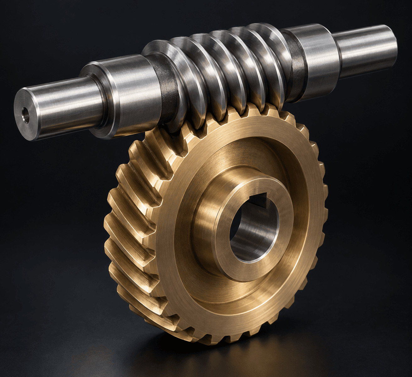
These visual modules support the profile, mesh, starts, lead and manufacturing concepts specified in the drawing.Worm shaft and worm wheel
The worm should be reviewed as one half of the complete gear mesh.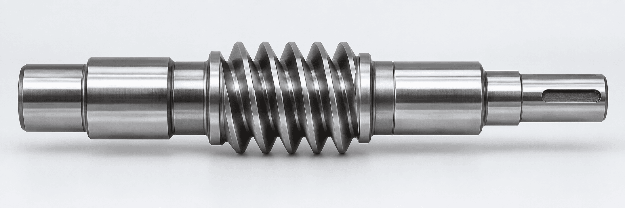
Shaft and worm geometry
Bearing journals, shoulders, worm section and drive-end features share a common datum plan.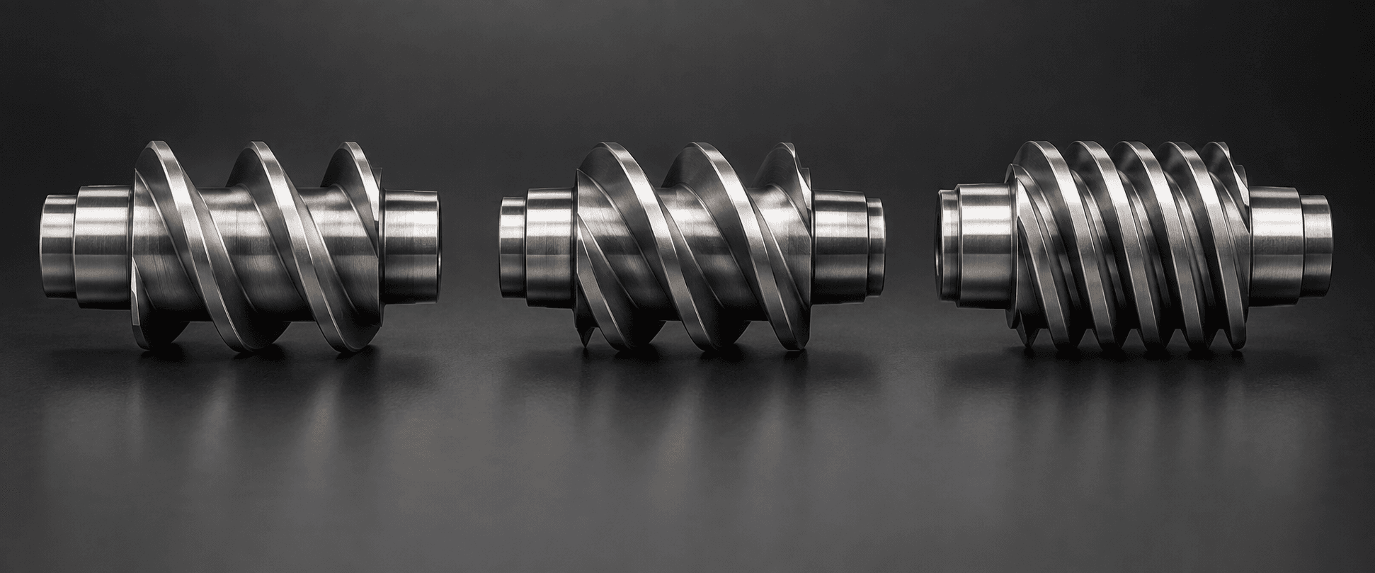
Single and multi-start
Starts change lead, lead angle, mating wheel geometry and reduction ratio.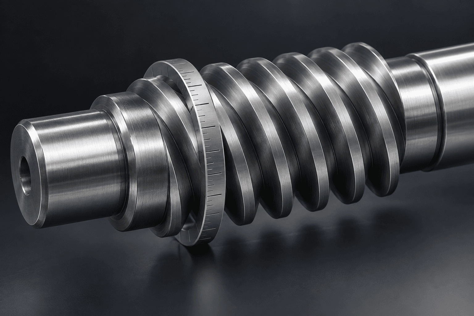
Lead and lead angle
Lead is a functional gear parameter, not just a visual helix angle.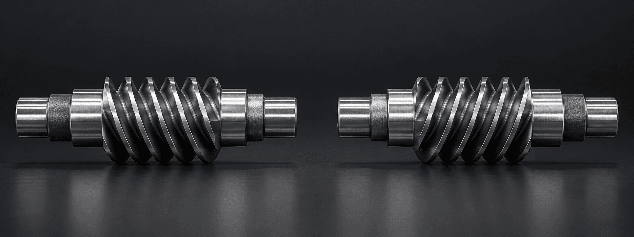
Right-hand or left-hand
Helix hand must match the intended worm-wheel configuration and force direction.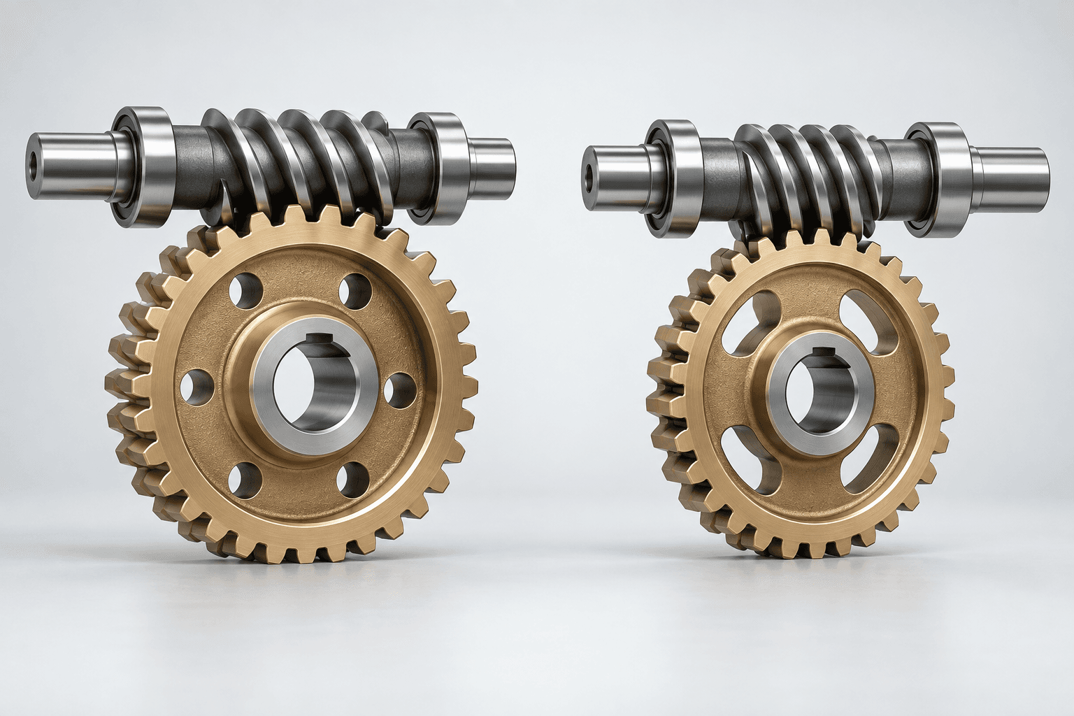
Reduction relationship
Starts and worm-wheel tooth count define the basic ratio of the pair.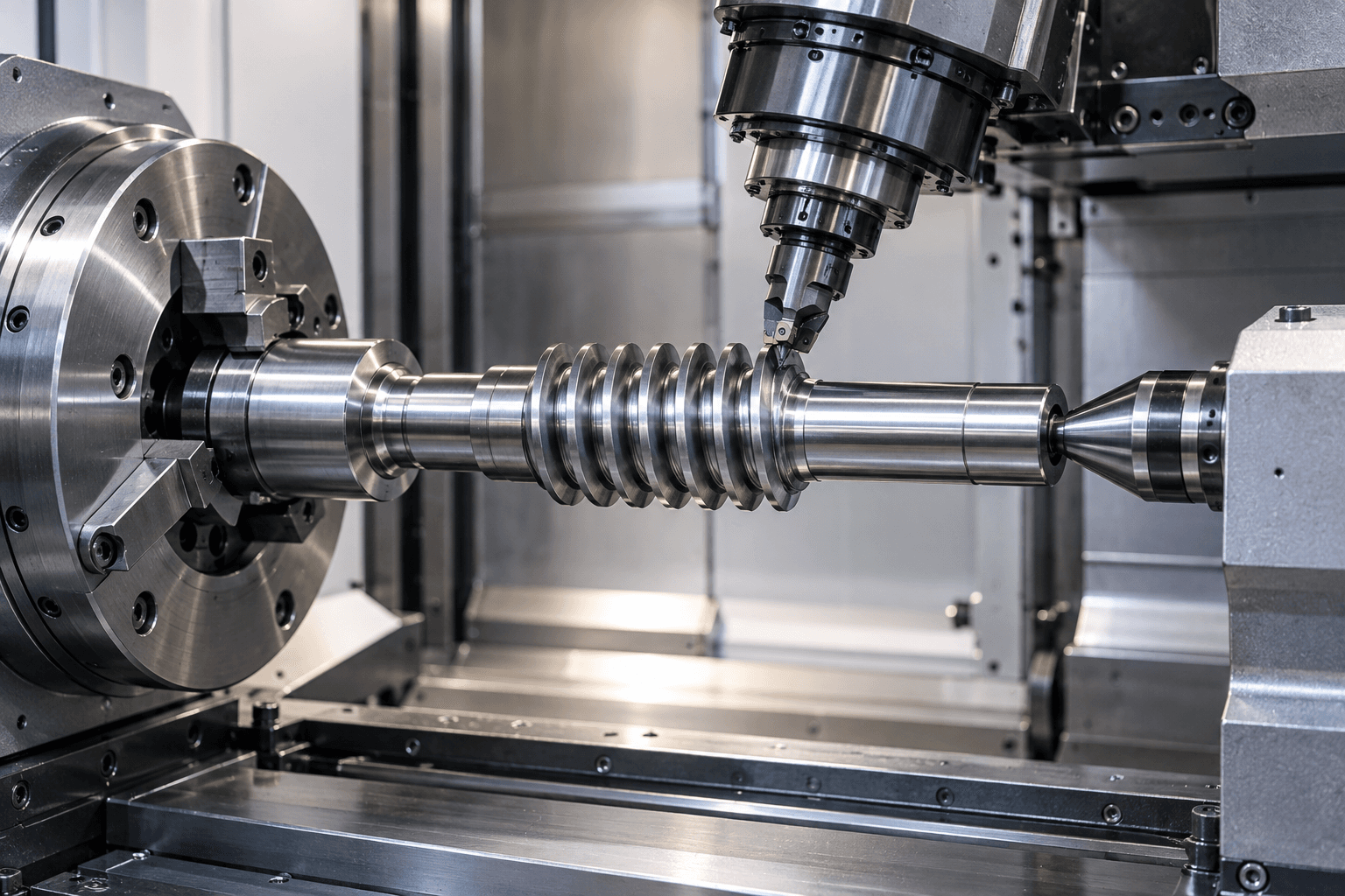
Worm profile machining
The process follows the approved profile and working geometry—not a generic thread callout.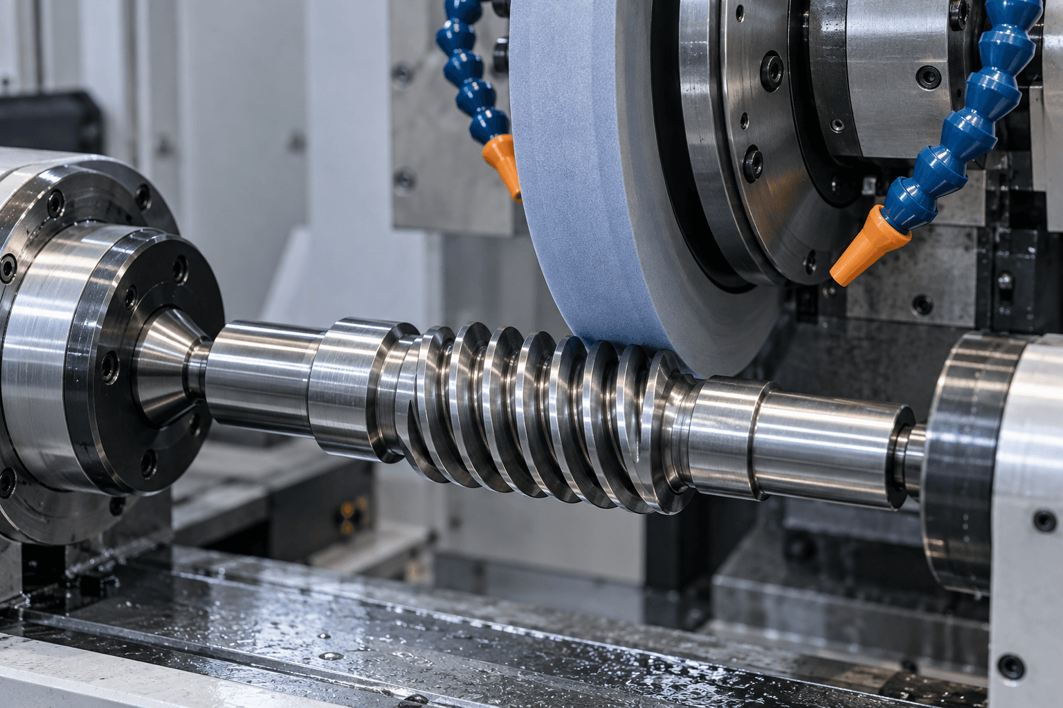
Post-treatment grinding
Grinding can refine hardened flanks, lead accuracy and surface condition.PAIR-LEVEL DESIGN DATA
Worm geometry must agree with the mating wheel.
The worm cannot be fully defined from one diameter or a general “module” callout. Its reference system and pair-level assembly data matter.Starts and reduction ratio
For a basic pair, ratio equals worm-wheel tooth count divided by worm starts: i = z₂ / z₁. A change in starts changes the ratio and the required pair geometry.Pitch and lead
Axial pitch is the spacing between adjacent threads. Lead is the axial advance of one helix in a full revolution; for a multi-start worm, lead equals axial pitch × starts.Lead angle
At the reference cylinder, tan γ = L / (πd). Lead, reference diameter and starts therefore work together and affect the mesh.Axial vs. normal reference
Axial module, normal module and their pressure-angle references are not automatically interchangeable. The drawing must identify its intended reference system.Center distance and backlash
Center distance, wheel geometry and installed backlash are pair- or assembly-level characteristics. A correct worm alone does not guarantee correct contact.Sliding contact and thrust
Worm meshes have substantial sliding contact and generate axial force. Lubrication, material pairing, bearings and duty affect the final system behavior.PROFILE—TREATMENT—FINISHING WORKFLOW
How are custom worm shafts manufactured?
The route is selected from the actual worm profile, material, accuracy, treatment and working-surface requirements.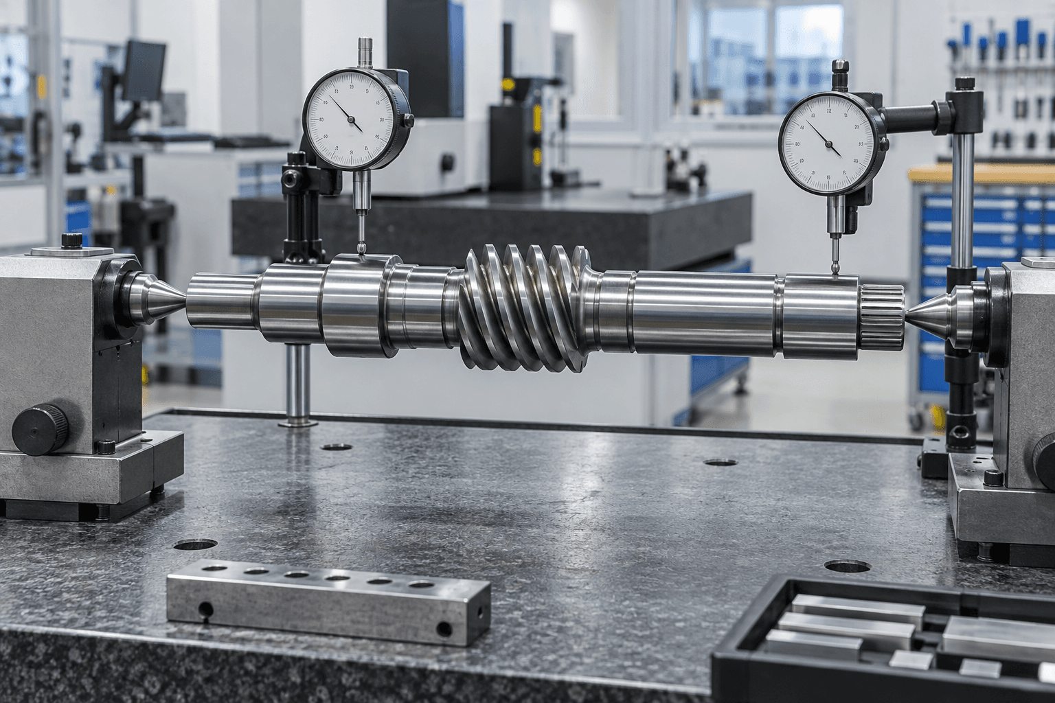
WORM-TO-JOURNAL ALIGNMENT
The bearing journals define the operating worm axis.
Accurate worm teeth alone are not enough. If the worm profile is eccentric to the bearing journals, the effective mesh can vary through each revolution and affect backlash, contact, vibration and wear.- Number of starts, hand, module or pitch and pressure-angle reference
- Lead, lead angle, reference diameter and working worm profile
- Worm runout and relationship of the profile to the journal axis
- Journal diameter, roundness, cylindricity, fit and surface roughness
- Specified hardness, case depth and post-treatment condition
SLIDING CONTACT AND THRUST
Worm drive behavior belongs to the complete system.
Worm gears have substantial sliding contact. Efficiency, heat, lubrication, material pairing, axial thrust and any self-locking behavior depend on the complete worm/wheel design and operating condition.No universal efficiency claim
Lead angle, speed, load, surface condition, lubricant, material pairing and bearing losses all affect transmission efficiency. It should be evaluated at system level.
Self-locking is not automatic
Backdriving behavior must not be assumed from the presence of a worm alone. Safety and holding requirements need a complete design review.
APPLICATION CONTEXT
Where are custom worm shafts used?
Worm gear reducers
Compact right-angle reduction for industrial drives.Electric actuators
Speed reduction and torque multiplication in rotary mechanisms.Automation & robotics
Rotary positioning, indexing and compact drive systems.Machine tools
Rotary tables, adjustment mechanisms and indexing equipment.Packaging & conveyors
Gearbox and mechanical-drive components for production machinery.Valve actuation
Drawing-defined reduction drives for rotary valves and actuators.Lifting & positioning
High-ratio drive arrangements requiring complete system safety review.Special-purpose machinery
Custom worm geometry where catalog parts do not fit the application.DFM GUIDANCE
Define the complete worm geometry before release.
Clear pair-level and machining information reduces the risk of quoting or manufacturing the wrong worm form.- 01
Specify the full worm form
Identify profile or standard, module or pitch reference, pressure angle, starts, lead, lead angle, hand, reference diameter and working length. - 02
Send the wheel information
For non-standard or new gear sets, provide wheel tooth count, wheel drawing, center distance, shaft angle and target backlash. - 03
Set the functional datums
Control worm geometry relative to the bearing-journal axis that supports the operating shaft. - 04
Mark finishing surfaces
Clearly identify worm flanks, bearing journals and seal surfaces that require grinding or special surface condition. - 05
Define treatment completely
State material, treatment process, surface and core hardness where relevant, case depth and any post-treatment requirements. - 06
Allow tool clearance
Adjacent shoulders and reliefs need enough clearance for worm cutting or grinding tools near the full working tooth length. - 07
Share operating data
Input RPM, torque, ratio, duty cycle, lubrication, temperature and rotation direction help evaluate the route. - 08
Avoid unsupported claims
Accuracy, efficiency, self-locking and assembly testing must follow the actual drawing and system requirement—not a generic worm assumption.
RELATED SHAFT TYPES
Worm gearing is not a generic thread or conventional gear tooth.
Worm Shaft vs. Threaded Shaft
A threaded shaft mates with a screw thread for fastening, adjustment or linear motion. A worm shaft meshes with a worm wheel to transmit rotation.Explore →Worm Shaft vs. Helical Gear Shaft
Helical gear shafts use conventional gear teeth in a helical gear pair. Worm shafts use screw-like geometry and usually drive a wheel on non-parallel axes.Explore →Worm Shaft vs. Gear Shaft
A gear shaft is the broader integral-gear category. Worm shafts have their own starts, lead, hand, profile and pair-level mesh requirements.Explore →Worm Shaft vs. Transmission Shaft
Transmission shaft describes torque-transfer function. Worm shaft describes the specialized worm-and-wheel gear geometry within that function.Explore →PREPARE YOUR RFQ
What is needed for a worm shaft quote?
Complete gear-pair data prevents false assumptions during the manufacturing review.- 01Worm profile or applicable standard, axial or normal module, pressure angle and reference system
- 02Starts, lead, lead angle, right- or left-hand helix, reference, outside and root diameters
- 03Working tooth length, profile/lead accuracy and specified worm or journal runout
- 04Mating worm-wheel drawing, tooth count, material, center distance, shaft angle and target backlash
- 05Overall shaft length, bearing journals, shoulders, threads, keyways, splines, grooves and drive ends
- 06Material, treatment, hardness, case depth, coating, surface finish and inspection documents
- 07Input RPM, torque, ratio, duty cycle, lubrication, temperature and direction of rotation
- 08Prototype or production quantity, annual demand and target delivery
WORM SHAFT FAQS
Common engineering questions.
Technical guidance for gearbox, actuator and power-transmission teams.What is a worm shaft?+
A worm shaft is a rotating shaft containing a screw-like gear profile designed to mesh with a mating worm wheel for compact reduction and right-angle power transmission.
What is the difference between a worm shaft and a threaded shaft?+
A threaded shaft uses screw threads mainly for fastening, positioning or linear movement. A worm shaft uses gear geometry to mesh with a worm wheel and transmit rotational power.
What does the number of starts mean?+
Starts are the independent helices on the worm. They influence the mating geometry, lead, lead angle and reduction ratio of the complete worm-and-wheel pair.
How is worm gear ratio calculated?+
For a basic worm pair, the ratio is the number of teeth on the worm wheel divided by the number of worm starts. The complete pair must still be reviewed around its actual geometry and duty.
Are worm gear drives always self-locking?+
No. Backdriving and self-locking depend on lead angle, friction, lubrication, material pairing, surface finish and operating condition. They should be evaluated at the complete system level.
Why do worm shafts generate axial thrust?+
The helical worm geometry creates an axial force component during torque transmission, so the bearing arrangement may need to support thrust as well as radial load.
Why are precision worm shafts ground?+
Grinding can improve worm profile, lead accuracy, surface condition and post-heat-treatment dimensional control. Journal grinding separately controls bearing fit and the rotational axis.
What is needed for a worm shaft quote?+
Provide the drawing, complete worm geometry, material and treatment, accuracy requirements, quantity and—where available—the mating worm-wheel drawing and gearbox center distance.
READY TO START?