
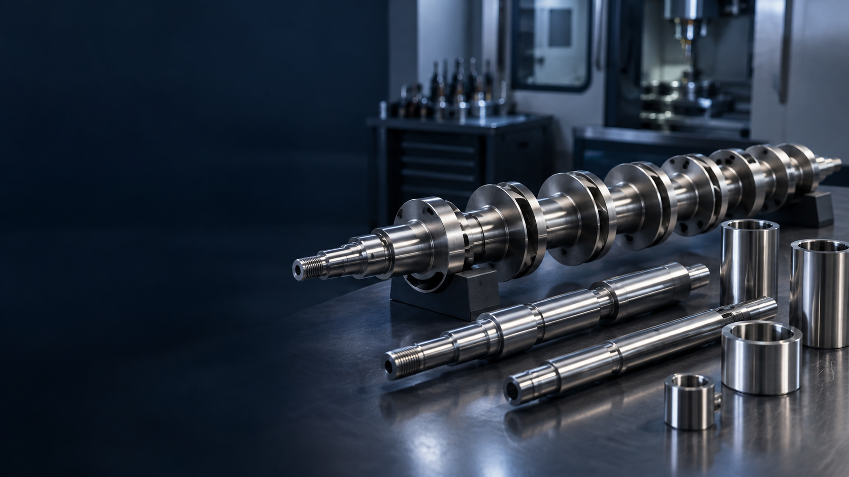
PUMP SHAFT MANUFACTURING
Custom Pump
Shaft Manufacturer
Pump Precision, Configured for Flow. Custom centrifugal, impeller, multistage, vertical and process-pump shafts manufactured around bearing alignment, seal interfaces, shaft deflection, corrosion and pump-specific operating requirements.BEARINGS / SEALS / IMPELLERS / GRINDING / INSPECTIONPUMP SHAFT CAPABILITY SNAPSHOT
Precision Rotation
For Pump Rotors.
TOPSHAFT manufactures custom precision shaft components used inside pump rotor systems. The shaft transmits torque while supporting bearings, impellers, sleeves, couplings and seal-related interfaces within the approved customer design.| Capability | TOPSHAFT support |
|---|---|
| Manufacturing focus | Custom pump, impeller, multistage, vertical, process and positive-displacement pump shaft components |
| Rotor functions | Torque transfer, bearing support, impeller location, seal/sleeve interfaces and coupling connection |
| Functional geometry | Bearing and seal journals, impeller seats, sleeves, shoulders, keyways, threads, bores and coupling ends |
| Critical controls | Straightness, runout, journal relationships, surface finish, hardness and corrosion requirements |
| Processes | Turning, milling, deep-hole work, heat treatment, cylindrical grinding, finishing and inspection |
| Project support | Prototype, replacement review, first article, OEM repeat production and drawing revision control |
PRECISION SHAFT SOLUTIONS FOR PUMP SYSTEMS
Built Around
The Pump Architecture.
Pump type, rotor layout, bearing support, impeller arrangement, fluid exposure and seal design help define the shaft's functional geometry and manufacturing route.PUMP SHAFT APPLICATIONS AT A GLANCE
Match The Shaft
To The Pump System.
A pump type → shaft type → critical-to-quality relationship gives buyers and engineers a clearer route from system requirements to drawing review.| Pump system | Typical shaft configuration | Main engineering requirements |
|---|---|---|
| Single-stage centrifugal pump | Pump / impeller shaft | Bearing fits, impeller seat, seal surface, runout |
| Multistage pump | Long multi-impeller shaft | Straightness, deflection, multiple fits, axial thrust |
| Vertical pump | Long or coupled shaft | Straightness, bearing support, corrosion |
| Chemical process pump | Stainless or alloy shaft | Fluid compatibility, corrosion, seal interface |
| Positive-displacement pump | Drive, gear or eccentric shaft | Torque, wear, alignment |
| Reciprocating pump | Crankshaft, eccentric or camshaft | Offset geometry, fatigue, journal accuracy |
| Close-coupled pump | Motor / pump interface shaft | Bearing fit, rotor and impeller alignment |
| High-speed pump | Precision pump shaft | Runout, critical-speed and balance-sensitive geometry |
WHERE DOES THE SHAFT FIT INSIDE A CENTRIFUGAL PUMP?
One Rotor.
Several Interfaces.
A pump shaft carries the relationship among driver, coupling, bearing support, seal region, impeller and casing. The customer's drawing identifies the component scope and functional datums.Motor → Coupling → Drive-End Bearing → Pump Shaft → Mechanical Seal / Shaft Sleeve → Impeller → Pump Casing
What the shaft can carry
- Coupling and drive-end interfaces
- Bearing journals and axial-location shoulders
- Seal regions and replaceable protective sleeves
- Impeller seats, keys, threads or retaining geometry
- Multistage spacers, balance components and additional impellers
WHAT MAKES A PUMP SHAFT DIFFERENT?
The Shaft Carries Torque
And Defines Rotor Alignment.
A pump shaft is more than a drive bar. It must transmit torque, support the impeller, establish rotating geometry, work with bearings and pass through a sealing system.Engineering focus
- Impeller alignment, bearing journals and seal region
- Functional runout, straightness and shaft deflection
- Corrosion, wear and customer-defined material route
WHY DOES PUMP-SHAFT DEFLECTION MATTER?
Control The
Functional Relationship.
Impeller hydraulic forces, coupling loads, rotor mass, radial bearing reactions and axial thrust can influence the complete rotor. Excessive deflection can alter seal loading, bearing alignment, clearances and vibration behavior.Useful drawing controls
- Straightness and journal-to-journal relationship
- Functional runout at impeller and seal interfaces
- Long-shaft bearing support and critical-speed context
CRITICAL SPEED & VIBRATION
Provide RPM For
Sensitive Rotors.
High-speed, long or dynamically sensitive pump rotors need the correct application context. TOPSHAFT does not claim complete rotor-dynamic design; operating RPM and customer-defined vibration requirements should be provided during engineering review.Helpful information
- Operating and maximum RPM
- Rotor length, bearing spacing and impeller arrangement
- Customer-defined critical-speed or vibration requirements
MECHANICAL SEAL & SHAFT INTERFACE
The Seal Region
Is A Functional Surface.
The shaft passes through the stationary casing. Seal-journal diameter, runout, surface condition, sleeve fit and shoulder position can all be relevant to the drawing-defined sealing arrangement.Pump shaft + sleeve + seal
- A shaft sleeve can protect selected shaft areas from wear or chemical exposure
- Surface requirements should be based on the approved seal/sleeve design
- TOPSHAFT manufactures the shaft component, not the complete seal system
PUMP SHAFT VS. SHAFT SLEEVE
Structural Component
And Protective Component.
The pump shaft is the primary rotating structural component that transmits torque and locates rotor elements. A shaft sleeve is a replaceable protective component installed around the shaft in selected regions.A sleeve may protect against
- Seal contact and mechanical wear
- Chemical exposure in selected services
- Local damage without replacing the whole shaft
BEARING & IMPELLER INTERFACES
Fit Alone Is Not
The Whole Requirement.
An impeller may use a key, interference fit, thread, taper, spline, retaining nut or other drawing-defined geometry. The functional relationship is impeller seat ↔ bearing journals ↔ seal interface.Review points
- Journal diameter, roundness, cylindricity and finish
- Impeller retention and shoulder location
- Datum references for impeller-seat runout
CRITICAL PUMP SHAFT CHARACTERISTICS
Inspect The Features
That Affect The Rotor.
Pump performance is a complete system outcome. The component drawing should identify which features and datums TOPSHAFT must control and inspect for the shaft's functional role.| CTQ | Why it matters |
|---|---|
| Bearing journal diameter | Controls bearing fit |
| Journal roundness | Supports stable rotation |
| Journal coaxiality | Defines the rotor axis |
| Shaft straightness | Important for long and multistage shafts |
| Shaft runout | Controls rotating geometry |
| Impeller seat diameter | Controls impeller fit |
| Impeller-seat runout | Supports rotor alignment |
| Seal journal | Interfaces with seal or sleeve system |
| Surface roughness | Important for bearings, seals and fitted surfaces |
| Shoulder position | Controls axial rotor-component location |
| Keyway / thread geometry | Controls torque and retention |
| Hardness | Supports wear and fatigue where required |
| Corrosion resistance | Important for wetted shaft applications |
MATERIALS FOR PUMP SHAFT MANUFACTURING
Selected Around
The Service Condition.
Material selection depends on load, fluid chemistry, temperature, corrosion, wear and customer specifications. No pump shaft material is universally suitable for every fluid or operating condition.Discuss Your Material Requirement →| Material direction | Typical application | Main consideration |
|---|---|---|
| 1045 / C45 | General-duty pump shafts | Strength and machinability |
| 4140 / 42CrMo | Higher-load pump shafts | Strength and toughness |
| 17-4PH stainless | High-strength corrosion-resistant shafts | Strength plus corrosion resistance |
| 304 / 316 stainless | Corrosive or wet environments | Corrosion resistance |
| Duplex stainless | Customer-specified demanding corrosion service | Corrosion plus strength |
| Nickel / specialty alloys | Aggressive process conditions | Fluid compatibility |
| Customer-specified alloy | Process and chemical pumps | Application-specific requirements |
CORROSION & SURFACE PROTECTION
Specify The Surface Route.
For wetted or corrosive applications, fluid chemistry, concentration, temperature and exposure conditions should guide the selected material and finish.Possible project requirements
- Passivation for stainless components where specified
- Polishing, electroless nickel or other specified coating
- Surface and material certificates where agreed
- Controlled seal or sleeve surface condition
HEAT TREATMENT FOR PUMP SHAFTS
Plan Thermal Processing
Around Functional Fits.
Critical journals may be finish-machined or ground after treatment where the drawing requires it.Potential routes
- Quenching and tempering for higher-strength alloy steels
- Induction hardening on selected journals or coupling interfaces
- Nitriding for compatible wear requirements
- Age hardening for 17-4PH where specified
- Stress relieving for long or heavily machined shafts
PUMP SHAFT MANUFACTURING PROCESSES
Linked Processes
For Rotor Geometry.
Turning, secondary features, treatment, grinding and inspection are planned as a connected route around bearing, seal, impeller and coupling interfaces.CNC Turning
Bearing journals, impeller seats, shoulders, seal regions, threads and shaft extensions.
Swiss-Type Turning
Smaller precision pump and motor-shaft components.
CNC Milling
Keyways, flats, cross holes and custom interfaces.
Deep-Hole Machining
Hollow pump shafts, internal passages and special long geometry.
Precision Grinding
Bearing journals, seal journals, impeller fits and hardened diameters.
EDM & Secondary Finishing
Selected specialized or hardened features where drawing requirements justify it.
FROM PUMP DRAWING TO FINISHED SHAFT
Build The Route
Around The Rotor.
Projects are reviewed around the customer's pump architecture, critical datums, material, treatment, fluid exposure, inspection and commercial requirements. Final pump performance is validated by the customer in the complete assembly.- 01Pump Architecture & Drawing ReviewPlanned around the approved drawing and confirmed project requirements.
- 02Identify Bearings, Impeller & Seal InterfacesIdentify functional bearing, impeller, seal, sleeve and coupling relationships.
- 03Define CTQs, Datums & Material RoutePlanned around the approved drawing and confirmed project requirements.
- 04CNC Shaft MachiningPlanned around the approved drawing and confirmed project requirements.
- 05Keyways, Threads, Bores & Secondary FeaturesPlanned around the approved drawing and confirmed project requirements.
- 06Heat Treatment If RequiredPlanned around the approved drawing and confirmed project requirements.
- 07Precision Grinding & Surface FinishingPlanned around the approved drawing and confirmed project requirements.
- 08Runout, Straightness & Journal InspectionInspect drawing-specified runout, straightness, journal, surface and interface features.
- 09Documentation & DeliveryPlanned around the approved drawing and confirmed project requirements.
Pump review → Rotor datums → Process plan → Machining → Treatment → Grinding → Inspection
PROTOTYPE, REPLACEMENT & REPEAT PRODUCTION
Support The Pump Project Lifecycle.
Different pump programs require different commercial paths. TOPSHAFT can review approved-drawing requirements for new development, repeat OEM supply and suitable replacement-component projects.Typical project stages
- New development: prototype shaft and first article
- OEM production: controlled drawing revisions and repeat supply
- Existing pump replacement: legacy drawing or sample feasibility review
- Final application validation: customer verifies the complete pump system
PUMP SHAFT QUALITY CONTROL
Measure The Functional Features.
Inspection methods are selected around the drawing and agreed project requirements.Possible controls
- Micrometers, dial indicators, gauges, CMM and optical measurement
- Bearing, seal and impeller journal dimensions
- Runout, straightness, shoulder, keyway and thread features
- Roughness, hardness, material and documentation requirements
DFM CONSIDERATIONS FOR PUMP SHAFTS
Define The Rotor Interfaces Early.
Useful engineering input enables a clearer manufacturing review and focuses precision controls on surfaces that affect the actual pump assembly.Helpful DFM inputs
- Pump type: centrifugal, multistage, vertical, chemical or positive-displacement
- Bearing locations and impeller interface method
- Seal/sleeve diameter, finish and shoulder requirements
- Operating RPM, fluid, temperature and corrosion context where relevant
- Material, treatment, hardness, straightness and runout datums
WHY TOPSHAFT FOR PUMP SHAFT MANUFACTURING
Pump Context, Shaft-Focused Delivery.
TOPSHAFT combines drawing-led component manufacturing with review of the shaft's practical role in a pump rotor system.Project approach
- Review bearing, impeller, seal, sleeve and coupling interfaces together
- Support long, multistage, vertical, hollow and corrosion-conscious shaft requirements
- Manufacture and inspect to approved drawing requirements
- Support prototype, replacement review, first article and repeat OEM production
WHAT INFORMATION IS NEEDED FOR A PUMP SHAFT QUOTE?
Send The Data That Defines The Pump Rotor.
Complete pump, geometry, interface, precision, material and commercial information enables a more useful engineering review.Upload Your Pump Shaft Drawing →| Information group | Include where available |
|---|---|
| Pump information | Pump type, centrifugal/multistage/vertical/positive displacement, RPM, application, fluid and temperature |
| Shaft geometry | Overall length, bearing journals, impeller seats, seal journals, shoulders, threads, sleeves and internal bore |
| Torque & interfaces | Keyway, spline, coupling seat, thread, taper and impeller retention method |
| Precision requirements | Bearing fits, runout, straightness, coaxiality, roundness, cylindricity, roughness and GD&T |
| Material & treatment | Material grade, treatment, hardness, passivation, coating and corrosion requirement |
| Commercial requirements | Prototype and production quantity, annual demand, inspection documents, material certificates and target delivery |
RELATED PUMP SHAFT SOLUTIONS
Follow The Pump Architecture.
01Custom ShaftGeneral pump-shaft geometry→02Stepped ShaftLong and multi-diameter shaft sections→03Hollow ShaftInternal bore or vertical-pump routing→04Motor ShaftMotor-to-pump interface→05Drive ShaftPump drive connections→06Gear ShaftRotary positive-displacement pumps→07Spline ShaftTorque-transfer interfaces→08CrankshaftReciprocating pump motion→09Eccentric ShaftMetering and reciprocating systems→10Motor IndustryDriver-side system context→
View All Precision Shaft Products →PUMP SHAFT FAQS
Answers For The Pump Drawing Review.
Practical questions for pump OEMs, repair organizations, process-equipment teams and industrial buyers.What does a pump shaft do?+
A pump shaft transmits torque from the driver to the pump impeller or displacement element while supporting and aligning rotating components such as bearings, sleeves and couplings.
What types of pump shafts can TOPSHAFT manufacture?+
Projects can be reviewed for centrifugal, impeller, multistage, vertical, process, positive-displacement, drive and custom pump shaft components to an approved drawing.
What is the difference between a pump shaft and an impeller shaft?+
An impeller shaft describes the pump-shaft role at the impeller interface. In many centrifugal pumps, the same structural shaft also carries bearing, seal, sleeve and coupling functions.
What is the difference between a pump shaft and a shaft sleeve?+
The pump shaft is the primary rotating structural component. A shaft sleeve is a replaceable protective component installed around selected areas to help protect the shaft from wear, seal contact or chemical exposure.
Why does pump-shaft straightness matter?+
Straightness is important because it can influence the relationship among bearing journals, seal region, impeller and other rotor components—especially on longer or multistage shafts.
Why is pump-shaft runout important?+
Runout controls variation of a rotating surface relative to a defined datum axis. Drawing controls should reflect the functional bearing, impeller and seal relationship.
What materials are used for pump shafts?+
Materials are selected according to mechanical load, corrosion, temperature, wear and contact with pumped fluid. Carbon/alloy steels and corrosion-resistant stainless or specialty alloys may be used depending on the application.
Can TOPSHAFT manufacture stainless-steel pump shafts?+
Stainless pump-shaft projects can be evaluated around material grade, fluid information, temperature, corrosion requirements, treatment, finishing and drawing-defined inspection.
Can you manufacture long multistage or vertical pump shafts?+
Long-shaft projects can be reviewed around length-to-diameter ratio, straightness, bearing support, coupling sections, material, transport and inspection requirements.
Can bearing and seal journals be precision ground?+
Where specified, final grinding can control selected bearing, seal, impeller and other functional diameters after machining or thermal processing.
Can pump shafts be heat treated?+
Specified quench and temper, induction hardening, nitriding, age hardening or stress-relieving routes can be evaluated according to material and drawing requirements.
How does corrosion affect pump-shaft material selection?+
Where a shaft or sleeve is exposed to the pumped fluid, material selection should consider fluid chemistry, concentration, temperature and operating conditions. No material is universally corrosion-proof.
Can TOPSHAFT manufacture crankshafts or eccentric shafts for positive-displacement pumps?+
Drawing-specified crankshaft, eccentric, cam, gear, spline and drive-shaft components can be reviewed for compatible positive-displacement pump applications.
Can you manufacture replacement pump shafts?+
Where suitable, legacy drawings, existing samples and mating bearing or impeller information can be reviewed for replacement-component feasibility. Final geometry is confirmed through the approved project requirements.
What information is required for a pump-shaft quotation?+
Provide pump type, drawing or CAD, operating RPM, pumped fluid where relevant, bearings, impeller and seal interfaces, material, treatment, critical tolerances, quantity and documentation requirements.
NEED A CUSTOM PUMP SHAFT?