
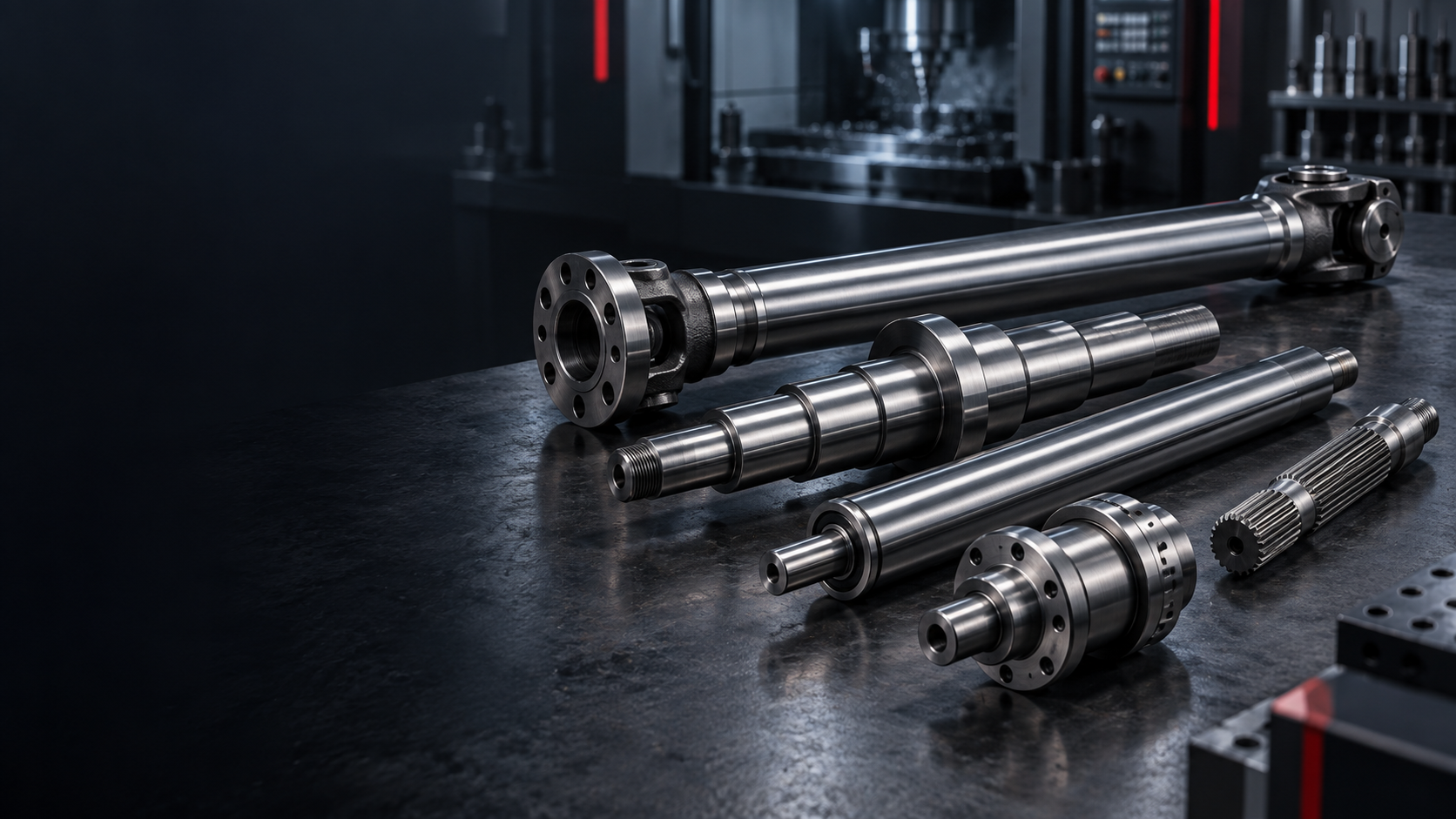
CUSTOM INDUSTRIAL MACHINERY SHAFT MANUFACTURER
Industrial Precision,
Built For Your Machine.
Custom drive, transmission, roller, spindle and motion shafts manufactured around the load, bearing, alignment and operating requirements of industrial equipment.POWER / ROLLERS / SPINDLES / MOTION / CUSTOM MACHINERYINDUSTRIAL SHAFT CAPABILITY SNAPSHOT
Designed Around The
Machine Function.
Topshaft manufactures custom precision shafts for industrial machinery, production equipment and mechanical systems. From main drive and transmission shafts to roller, spindle and stepped components, projects are reviewed around functional interfaces and actual operating conditions.| Capability | TOPSHAFT support |
|---|---|
| Manufacturing type | Custom / OEM / made to drawing |
| Industrial shaft roles | Drive, transmission, roller, spindle, stepped, gear, spline, linear and custom shafts |
| Machining | CNC turning, milling, gear and spline features, grinding and finishing |
| Materials | Carbon, alloy, carburizing and selected stainless steels; aluminum where applicable |
| Heat treatment | Q&T, induction hardening, carburizing, nitriding, stress-relieving and drawing-specified routes |
| Critical controls | Bearing fits, runout, straightness, coaxiality, surface finish, hardness and shaft deflection |
| Project support | Prototype, replacement drawing/sample review where appropriate, first article and repeat OEM production |
| Inspection | Dimensional, geometric, surface and drawing-specific inspection |
POWER TRANSMISSION THROUGH THE MACHINE
From Motor To
Machine Mechanism.
Industrial machinery often connects several shaft functions in one working system. Each interface should be defined around the assembly that will carry power, load and motion.Motor ↓ Gearbox ↓ Drive Shaft ↓ Roller / Spindle / Machine Mechanism
Industrial shaft manufacturing is system-aware geometry.
A machine shaft may transfer torque, carry a pulley, support a roller, locate a bearing, seal against a rotating interface and connect a coupling—sometimes in one component.
Can all functional features maintain the relationships required by the complete machine assembly?
PRECISION SHAFT SOLUTIONS FOR INDUSTRIAL MACHINERY
One Machine,
Several Shaft Roles.
Industrial machinery covers power transmission, conveying, rolling, machine tools and continuous production equipment. The shaft function determines the appropriate geometry, material and finishing route.INDUSTRIAL MACHINERY SHAFT APPLICATIONS AT A GLANCE
Match The Shaft To
The Machine System.
| Machine system | Typical shaft components | Main engineering requirements |
|---|---|---|
| Main Drive | Drive / transmission shaft | Torque, fatigue, coupling alignment |
| Conveyor | Roller / drive / gear shaft | Load, span, straightness, bearing fits |
| Web Handling | Roller shaft | Runout, deflection, concentricity |
| Machine Tool | Spindle shaft | Runout, stiffness, precision bearing seats |
| Packaging Machine | Roller / cam / eccentric shaft | Repeatability, alignment, timing |
| Printing Machine | Roller / drive shaft | Runout, straightness, surface control |
| Processing Machinery | Main / transmission shaft | Torque, fatigue, wear |
| Linear Automation | Linear motion / threaded shaft | Straightness, surface finish, fit |
| Heavy Machinery | Drive / stepped / spline shaft | Strength, shock load, heat treatment |
WHAT MAKES AN INDUSTRIAL MACHINERY SHAFT DIFFERENT?
Several Functions,
One Working Axis.
- 01Bearing JournalLocates the rotating shaft in the bearing system.
- 02Gear / Pulley SeatCarries a driven component and controls its position.
- 03Keyway / SplineTransfers torque to the connected component.
- 04Seal JournalSupports the defined sealing interface.
- 05Shaft ShoulderEstablishes axial location and assembly stack-up.
- 06Coupling EndConnects the machine drive path.
WHAT LOADS ACT ON INDUSTRIAL MACHINERY SHAFTS?
Torque Is Only
Part Of The Load.
Material, geometry, fillet radii, heat treatment and finishing are assessed around the conditions the shaft must support in service.- Torsional load: produced while transferring torque
- Bending load: from gears, belts, sprockets, rollers or overhung loads
- Axial load: from helical gearing, thrust mechanisms or process loads
- Cyclic load: from continuous machines and repeated production cycles
- Shock load: from impacts, starts/stops, jams or torque changes
WHY DOES SHAFT DEFLECTION MATTER?
Long Shafts Need
A Stable Span.
For long machine and roller shafts, shaft length, diameter, bearing spacing and load can affect bending deflection. Conveyors, rollers, mixing equipment, web handling and heavy drives can all require this relationship to be considered.Discuss Your Machinery Shaft →| Characteristic | Why it matters |
|---|---|
| Bearing Journal Diameter | Controls bearing fit |
| Journal Roundness | Supports smooth rotation |
| Straightness | Important for long shafts |
| Runout | Controls rotating interfaces |
| Coaxiality | Maintains alignment between shaft features |
| Shoulder Position | Controls axial assembly |
| Keyway / Spline Geometry | Transfers torque |
| Gear Seat Runout | Supports gear alignment |
| Surface Roughness | Important for bearings and seals |
| Hardness | Supports wear resistance |
| Case Depth | Important for hardened features |
| Shaft Deflection | Important for long loaded shafts |
SHAFTS FOR CONTINUOUS-DUTY MACHINERY
Build For Repeated
Working Cycles.
Industrial systems can run through repeated shifts and production cycles. Design and manufacturing priorities can include fatigue resistance, wear, bearing surfaces, lubrication interfaces, treatment, surface hardness and production consistency. Specific design-life requirements should be supplied with the project data.Fatigue
Repeated torque and bending loads should be considered in the supplied engineering requirements.
Wear
Contact surfaces, splines, gears and journals can need specified material or treatment.
Bearing surfaces
Journal geometry, roundness and finish support the intended bearing interface.
Lubrication interfaces
Grooves, seal areas and surface conditions should follow the drawing and assembly needs.
Production consistency
Repeat manufacturing follows the approved drawing and agreed inspection requirements.
MATERIALS FOR INDUSTRIAL MACHINERY SHAFTS
Choose Material For
The Working Requirement.
| Material | Typical application | Reason |
|---|---|---|
| 1045 / C45 | General machine shafts | Strength and machinability |
| 4140 / 42CrMo | Drive / transmission shafts | Strength and toughness |
| 4340 | High-load machinery | Higher mechanical performance |
| 8620 / carburizing steels | Gear / spline features | Hard surface with a tough core |
| 17-4PH stainless | Specialized machinery | Strength plus corrosion resistance |
| 304 / 316 stainless | Washdown / corrosive environments | Corrosion resistance |
| Aluminum | Lightweight mechanisms | Reduced mass |
Quenching & Tempering
For drive, transmission and high-load machine shafts where specified.
Induction Hardening
Selective wear surfaces such as bearing journals, splines and contact areas.
Carburizing
Relevant to gear shafts and spline features where a hard case is required.
Nitriding
Wear-resistant surfaces on compatible steel where specified.
Stress Relieving
May be relevant for long or heavily machined shafts requiring dimensional stability.
INDUSTRIAL SHAFT MANUFACTURING PROCESSES
Build The Features
In The Right Route.
Turning, milling, gear and spline features, treatment and precision finishing are planned around the supplied drawing and the functional role of the shaft.CNC Turning
Stepped diameters, bearing journals, shoulders, threads and grooves.
Swiss-Type Turning
Smaller, slender and repeat precision components where appropriate.
CNC Milling
Keyways, flats, holes and slots.
Gear / Spline Machining
Mechanical drive features manufactured to the supplied requirements.
Precision Grinding
Bearing journals, seal surfaces, hardened diameters and precision functional surfaces.
EDM & Secondary Features
Specialized hardened or difficult features where the drawing requires it.
FROM MACHINE DRAWING TO PRODUCTION SHAFT
Review The Function
Before The Route.
Industrial machinery shaft manufacturing begins with functional interfaces—not only nominal dimensions.- 01Application & Drawing ReviewPlanned around the drawing and confirmed project requirements.
- 02Identify Functional SurfacesIdentify bearing journals, drive features, seal surfaces and machine interfaces.
- 03Define Datums & CTQsConfirm drawing-defined datums, fits, runout, straightness and other CTQs.
- 04CNC MachiningPlanned around the drawing and confirmed project requirements.
- 05Gear / Spline / Secondary FeaturesPlanned around the drawing and confirmed project requirements.
- 06Heat TreatmentPlanned around the drawing and confirmed project requirements.
- 07Precision FinishingPlanned around the drawing and confirmed project requirements.
- 08Dimensional & Functional InspectionVerify dimensional, geometric, surface and treatment requirements.
- 09Production & DeliveryPlanned around the drawing and confirmed project requirements.
Drawing review → Functional surfaces → Datums & CTQs → Machining → Treatment → Finishing → Inspection
NEW OEM, REPLACEMENT & REPEAT PRODUCTION
Support The
Machine Lifecycle.
Industrial machinery projects can range from new equipment development to existing-machine replacement requirements.Project paths
- New OEM machinery: development drawings, prototypes, validation and repeat production
- Existing machinery: customer or legacy drawings can be reviewed for manufacturing
- Replacement components: physical samples may be reviewed where an appropriate manufacturing assessment is possible
- Repeat supply: manufacturing follows the approved drawing and agreed quality requirements
INDUSTRIAL SHAFT QUALITY CONTROL
Inspect The
Working Relationships.
Inspection methods and documentation are confirmed project by project during quotation and supplier qualification.Inspection may include
- Diameter, overall length, straightness, runout, coaxiality, roundness and cylindricity
- Keyway, spline, thread and shoulder dimensions
- Surface roughness, hardness and drawing-specified treatment checks
- Agreed dimensional reports, first-article records and material / treatment documentation
DFM CONSIDERATIONS FOR INDUSTRIAL MACHINERY SHAFTS
Make The Drawing
Support The Machine.
Clear functional requirements improve manufacturability, cost and production stability.Useful engineering inputs
- Identify bearings, gears, pulleys, sprockets, couplings and seals
- Establish datums around how the shaft operates in the actual machine
- Consider shaft length, bearing spacing and deflection for rollers, conveyors and long drives
- Define suitable fillet radii at loaded transitions
- Specify material, treatment, hardness, case depth and post-treatment finishing completely
- Provide RPM, torque, radial/axial load, duty cycle and environment where useful
WHY TOPSHAFT FOR INDUSTRIAL MACHINERY SHAFTS
Shaft-Focused,
Machine-Aware.
Industrial machine projects can bring turning, milling, drive interfaces, treatment, grinding and finishing into one controlled route.Project approach
- Review functional relationships, bearing fits, load paths and critical shaft features
- Support drawings, prototype quantities, validation quantities and repeat production
- Manufacture and inspect to the approved drawing and agreed quality requirements
- Link specialized shaft needs to the relevant individual product page
WHAT INFORMATION IS NEEDED FOR AN INDUSTRIAL SHAFT QUOTE?
Send The Data That
Defines The Machine Role.
Complete drawing, geometry, functional, precision, material, operating and commercial data enables a more useful engineering and process review.Upload Your Machine Shaft Drawing →| Information group | Include where available |
|---|---|
| Drawing | 2D drawing, 3D CAD and existing sample where applicable |
| Shaft geometry | Overall length, diameters, bearing journals, shoulders, bores, threads and grooves |
| Functional features | Keyways, splines, gears, coupling seats, pulley/sprocket seats and seal journals |
| Precision | Fits, runout, straightness, coaxiality, surface roughness and GD&T |
| Material / treatment | Material grade, heat treatment, hardness, case depth and surface treatment |
| Operating conditions | RPM, torque, load, duty cycle and operating environment |
| Commercial requirements | Prototype quantity, production quantity, annual demand, inspection documentation and delivery requirement |
RELATED INDUSTRIAL SHAFT SOLUTIONS
Follow The Machine Function,
Then Open The Product.
01Drive ShaftPower transfer through the machine→02Transmission ShaftInternal machine transmission→03Roller ShaftConveyor and web-handling systems→04Spindle ShaftMachine tools and rotating precision→05Stepped ShaftMultiple bearing, gear and seal locations→06Linear Motion ShaftGuidance and motion systems→07Spline ShaftTorque-transfer connections→08Gear ShaftIntegrated gear interfaces→09Eccentric ShaftReciprocating machine motion→10Hollow ShaftThrough-bore applications→
View All Precision Shaft Products →INDUSTRIAL MACHINERY SHAFT FAQS
Answers For The
Machine Drawing Review.
Practical questions for engineering, maintenance and sourcing teams.What types of shafts are used in industrial machinery?+
Industrial machinery can use drive, transmission, roller, spindle, gear, spline, stepped and linear motion shafts depending on whether the machine transmits torque, supports rollers, guides motion or maintains a rotating axis.
What industrial shafts can TOPSHAFT manufacture?+
Custom shaft projects can be reviewed from customer drawings and requirements for drive, transmission, roller, spindle, gear, spline, stepped, threaded, eccentric and other shaft components.
What materials are commonly used for industrial machine shafts?+
The material depends on load, environment, wear and treatment needs. Typical options include carbon steel, alloy steel, carburizing steel, selected stainless steels and aluminum for appropriate lightweight mechanisms.
How are long machinery shafts kept straight?+
Long-shaft geometry is reviewed around length, diameter, bearing spacing, load, process route and drawing-defined straightness requirements. Final controls depend on the supplied drawing and operating conditions.
Why does shaft runout matter in industrial equipment?+
Runout can affect rotating interfaces such as bearings, rollers, gears, seals and couplings. The required control should be established from the functional datum structure of the assembly.
Can TOPSHAFT manufacture roller and conveyor shafts?+
Roller and conveyor shaft projects can be evaluated from the shaft span, loading, bearing journals, pulley or sprocket interfaces, material, surface and quantity requirements.
Can TOPSHAFT manufacture machine-tool spindle shafts?+
Spindle shaft projects can be reviewed from bearing-seat, mounting-interface, runout, stiffness, material and final grinding requirements.
Can industrial shafts be heat treated?+
Specified routes such as quenching and tempering, induction hardening, carburizing, nitriding and stress relieving can be considered where compatible with the material and drawing requirements.
Can bearing journals be precision ground?+
Where specified, precision grinding can be used for critical bearing, seal and hardened functional surfaces.
Can TOPSHAFT manufacture replacement machinery shafts?+
Existing machinery projects can be reviewed from a customer drawing, legacy drawing, or physical sample where an appropriate manufacturing review is possible. Requirements are confirmed project by project.
Can you support prototype and repeat production?+
Projects can begin with prototype, validation or first-article quantities and progress to repeat OEM production when requirements are confirmed.
What information is required for an industrial shaft quotation?+
Provide the drawing or CAD model, geometry, functional interfaces, material and treatment, CTQs, operating conditions, quantity, documentation and delivery requirements.
NEED A CUSTOM INDUSTRIAL MACHINERY SHAFT?