
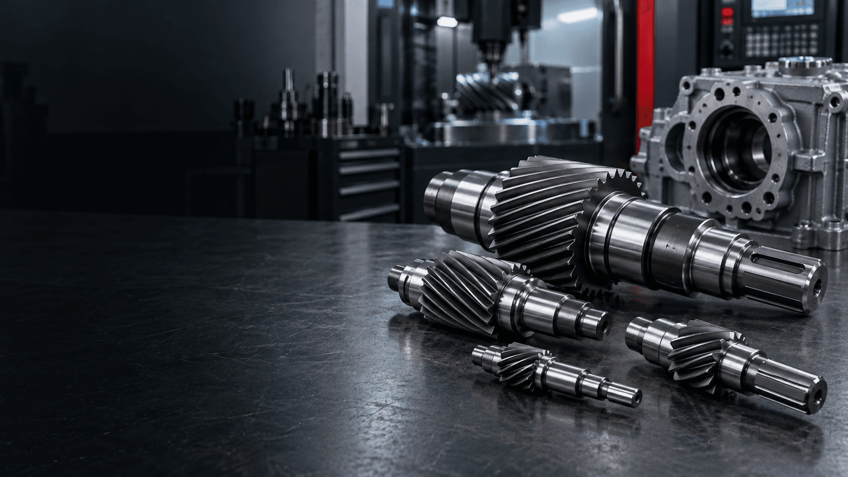
HELICAL GEAR SHAFT MANUFACTURING
Custom Helical
Gear Shaft
Precision helical gear shafts built to your drawing.
Topshaft manufactures custom helical gear shafts and helical pinion shafts for gearboxes, gear reducers, motors, automation systems and industrial power transmission.Gear geometry, bearing journal dimensions, gear-to-journal runout, concentricity, straightness, hardness and surface finish are reviewed around your technical drawing.
Send your 2D drawing, 3D model and gear specifications for engineering review.AT A GLANCE
Custom helical gear shaft capabilities
Every route is selected around the gear specification, shaft interfaces, heat treatment and functional inspection requirements.- Manufacturing type
- Custom / OEM / made to drawing
- Product types
- Helical gear shafts, helical pinion shafts and integrated gear shafts
- Shaft processes
- CNC turning, milling, grinding and secondary machining
- Gear geometry
- Made to customer drawing and approved gear specification
- Materials
- Carbon steel, alloy steel, stainless steel and specified machinable materials
- Shaft features
- Journals, shoulders, keyways, splines, grooves, threads, holes and tapers
- Heat treatment
- Specified treatment incorporated into the manufacturing route
- Inspection
- Dimensional, runout, concentricity, hardness and drawing-specific checks
ENGINEERING OVERVIEW
What is a helical gear shaft?
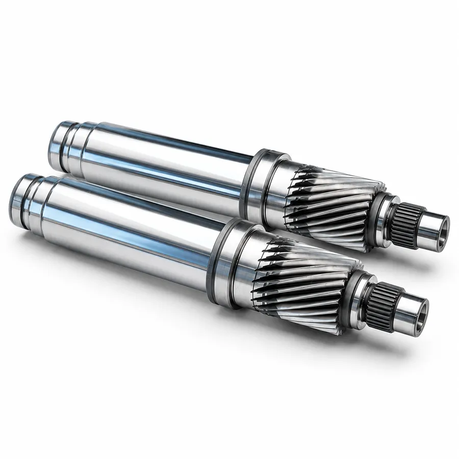
A helical gear shaft has helical gear teeth integrated directly into part of the shaft body. The gear and shaft can therefore be manufactured as one functional component.
Because the teeth are angled to the shaft axis, they engage progressively across the face width. This can support smooth torque transmission and compact drivetrain architecture.
Helical geometry also creates axial thrust, so bearing arrangement, shaft datums and gearbox design must be considered together.
GEAR SPECIFICATION
What specifications define a helical gear shaft?
Pressure angle
The drawing should identify the specified pressure angle and its reference plane where needed.Helix angle
Defines tooth inclination and influences contact characteristics and axial force.Helix direction
Right-hand or left-hand tooth direction must be identified for the mating gear arrangement.Tooth count & face width
Together they define transmission ratio, tooth contact area and load distribution.Gear accuracy
Specify the required gear accuracy system, profile or lead modification where applicable.INTEGRATED SHAFT FEATURES
What features can be combined with a helical gear shaft?
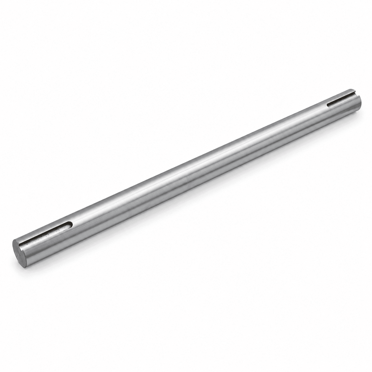
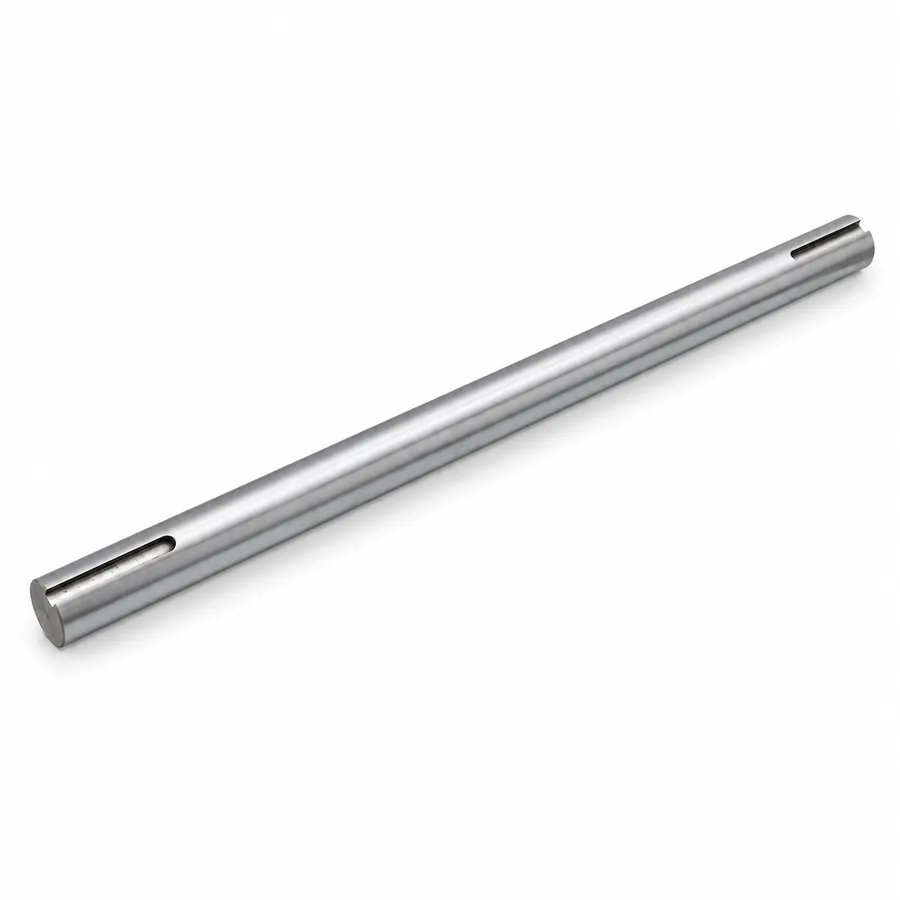
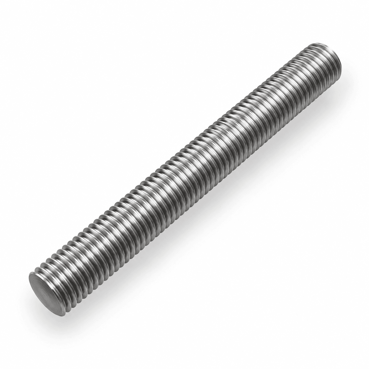
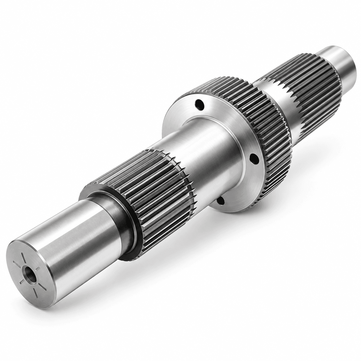
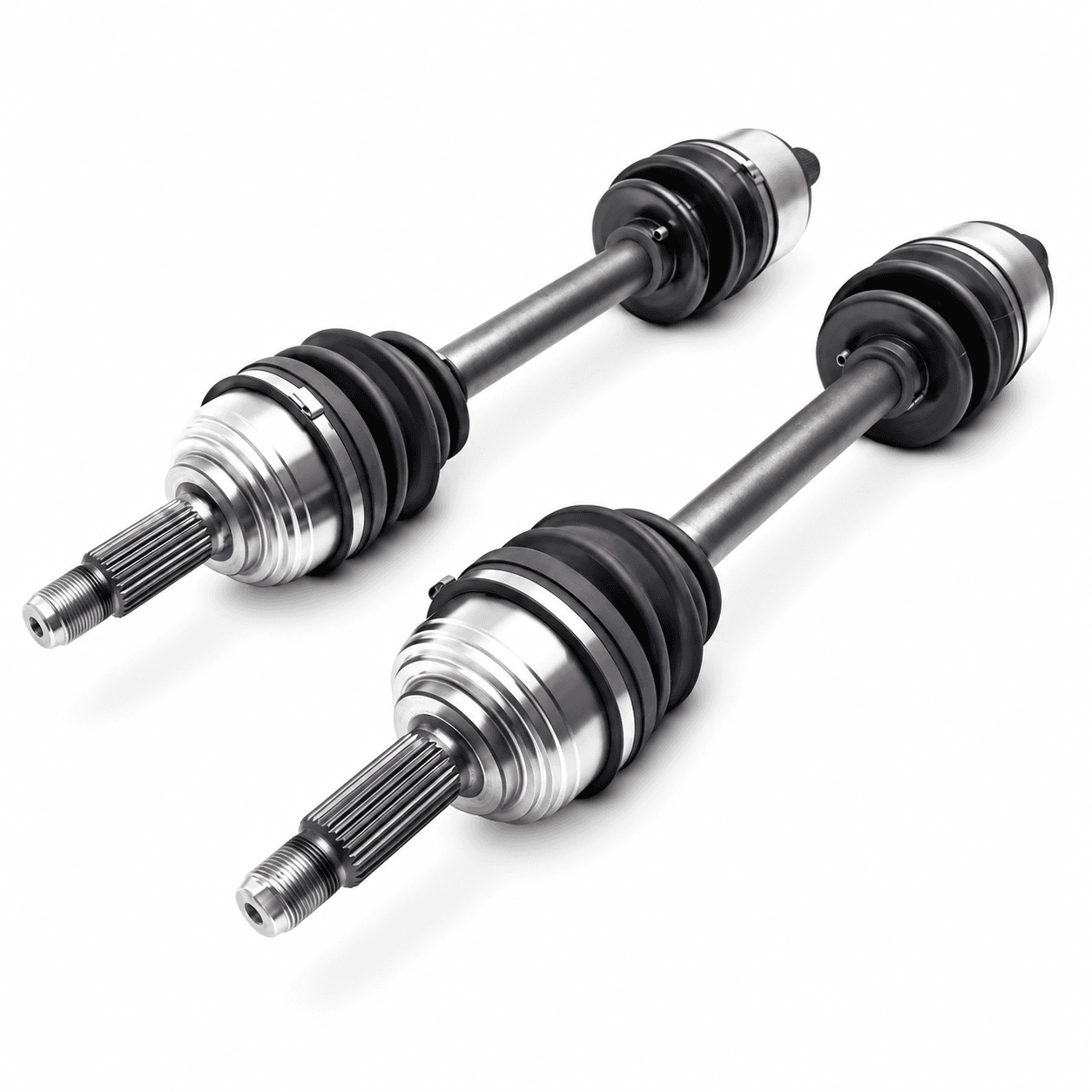
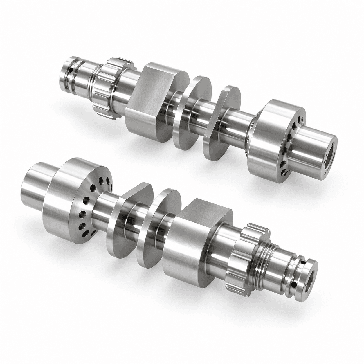
A helical gear shaft commonly combines the gear section with multiple locating, torque-transmission and assembly interfaces.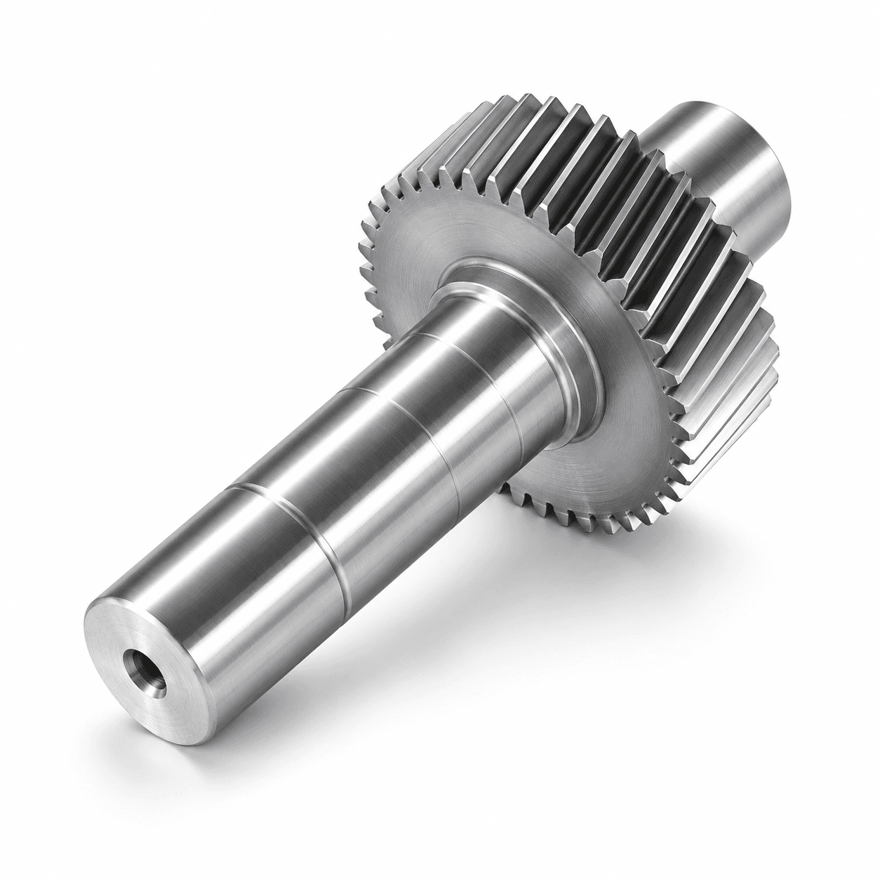
MANUFACTURING ROUTE
How are helical gear shafts manufactured?
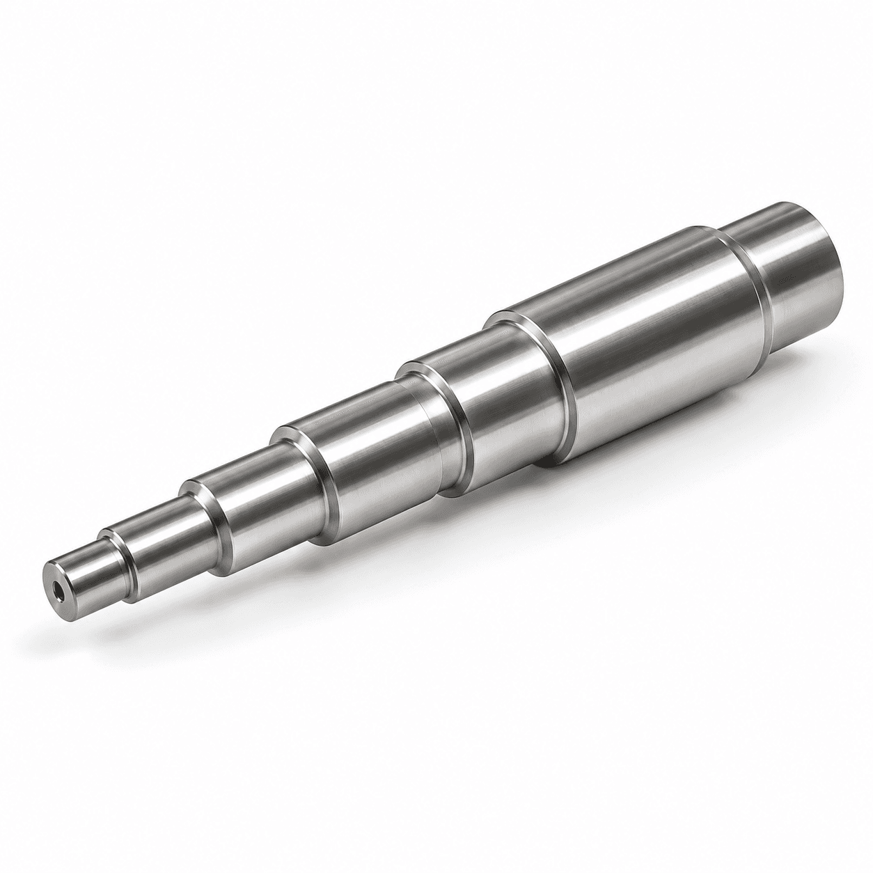
Precision helical gear shafts require coordinated shaft machining, gear-feature production, heat treatment, finishing and inspection.MATERIAL SELECTION
What materials are used for helical gear shafts?
Selection depends on transmitted torque, tooth contact stress, bending fatigue, wear, shaft load, heat treatment and operating environment.1045 / C45
General industrial gear shafts: strength, machinability and cost.4140 / 42CrMo
Higher strength and toughness for heavy-duty transmission shafts.4340
High-strength, fatigue-resistant applications.8620
Carburized components with wear-resistant gear teeth.20CrMnTi
Carburizing steel for gearboxes and transmission systems.40Cr
Industrial transmission components after heat treatment.304 / 316 stainless steel
Corrosion-resistant applications in wet or chemical environments.17-4PH
High strength plus corrosion resistance for specialized components.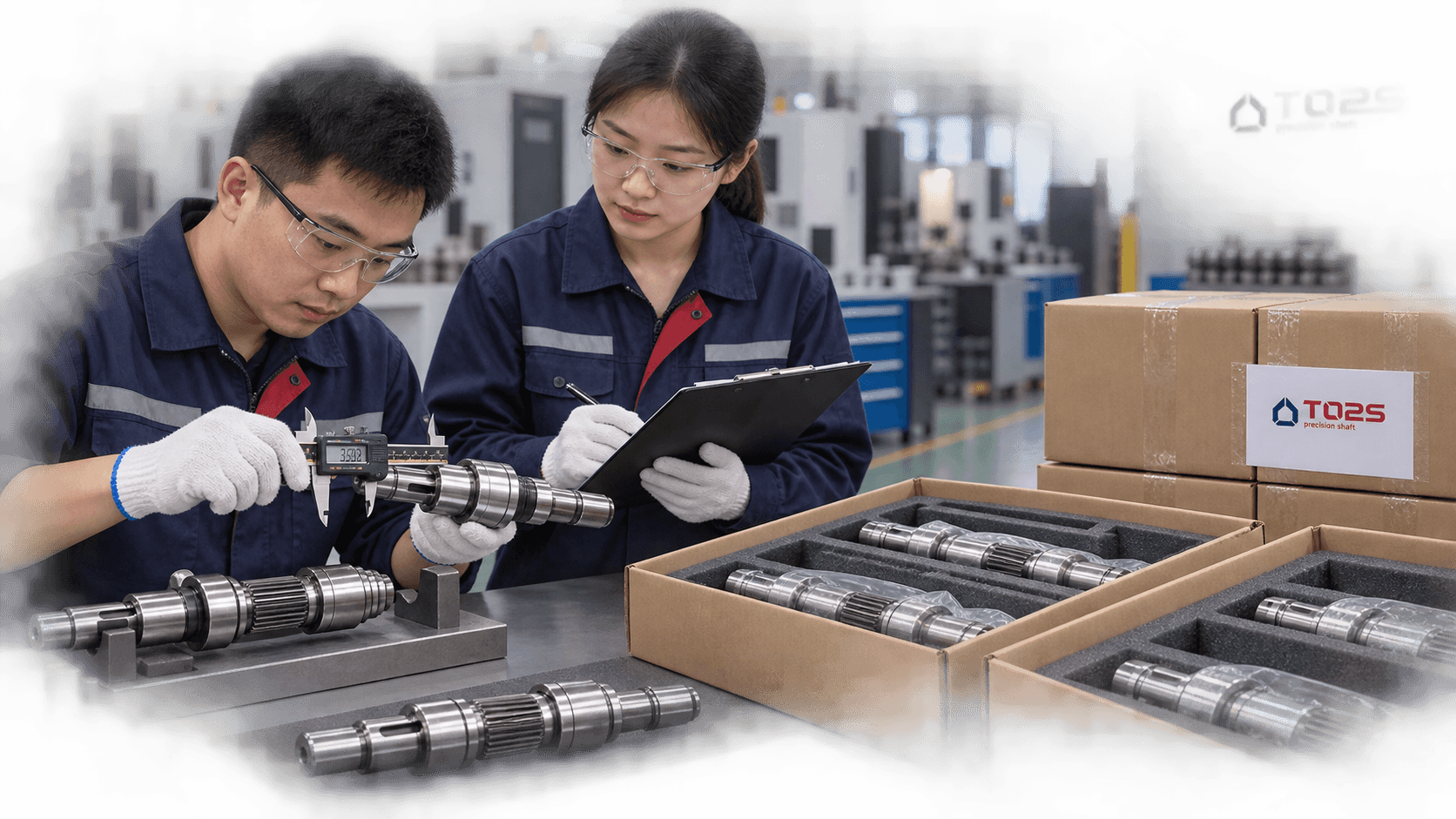
GEAR & SHAFT ACCURACY
Which tolerances matter on a helical gear shaft?
A helical gear shaft is not evaluated only by outside diameter. The relationship between gear teeth, bearing journals and the rotational axis affects drivetrain performance.- Gear-to-journal runout and the intended rotational datum
- Bearing-journal diameter, roundness and surface finish
- Concentricity, coaxiality and shaft straightness
- Tooth profile, helix geometry and tooth pitch
- Gear, seal and journal surface roughness
POST-MACHINING REQUIREMENTS
Heat treatment and gear finishing
Specified material properties, tooth wear resistance and critical surface performance are incorporated into the manufacturing route where required.Heat treatment
Carburizing, induction hardening, quenching and tempering, nitriding and through-hardening can be evaluated according to material and drawing requirements.
Finish machining
Critical bearing journals, locating surfaces and specified gear surfaces can be finish-machined or ground after heat treatment where the route requires it.
APPLICATION CONTEXT
Where are helical gear shafts used?
Industrial gearboxes
Transmit torque between gearbox stages while supporting bearings and transmission components.Gear reducers
Integrated pinion shafts for compact reduction systems.Electric gear motors
Motor-drive components for a first reduction stage.Robotics & automation
Compact transmission parts for actuators and automated machinery.Automotive & electric drives
Transmission, auxiliary-drive and powertrain mechanisms.Machine tools
Rotational motion within machine-tool drive systems.Industrial machinery
Packaging, printing, material handling and processing equipment.Pumps & mechanical drives
Gear transmission systems linking motors and driven assemblies.CONTROLLED WORKFLOW
How we manufacture a custom helical gear shaft
Gear teeth transmit torque while bearing journals define the rotation axis. The manufacturing and inspection route evaluates both functions together.- 01
Drawing review
Review module or DP, pressure angle, helix angle and hand, tooth count, material, journals and functional tolerances. - 02
Process planning
Plan the shaft, gear, heat-treatment, finishing and inspection sequence around the drawing. - 03
Material preparation
Prepare the specified steel or other material with appropriate machining allowance. - 04
Machine the shaft blank
Create journals, shoulders, grooves, thread blanks and the basic gear blank. - 05
Produce gear features
Manufacture the helical tooth geometry to the approved technical data. - 06
Secondary machining
Add keyways, splines, threads, flats, holes and drawing-specified features. - 07
Heat treatment
Apply the specified route for surface hardness, strength and wear performance. - 08
Finish critical surfaces
Finish-machine or grind journals and other critical surfaces where required. - 09
Inspect
Verify shaft and gear-related characteristics to the agreed inspection plan. - 10
Protect & package
Clean, protect and package finished components for transport.
WHY TOPSHAFT
A helical gear shaft partner for aligned, reliable transmission.
Shaft-focused manufacturing
Shaft geometry, journals, secondary features and gear section are considered as one component.Made to your drawing
Manufactured to customer drawings, CAD models and technical specifications rather than limited catalog sizes.Gear-to-journal relationship
Datums, machining sequence and inspection requirements are reviewed around the intended rotational axis.Complex shaft features
Support for journals, gear features, keyways, splines, threads, grooves, shoulders, holes and tapers.Prototype to production
Projects can progress from samples and engineering validation to recurring production.Engineering review
Drawing requirements that affect process selection, cost or lead time are reviewed before quotation.PREPARE YOUR RFQ
What information is needed for a helical gear shaft quote?
Share the gear data, shaft data, material requirements and commercial quantity so the route can be evaluated accurately.- 01Normal module or DP
- 02Pressure angle, helix angle and helix hand
- 03Tooth count and face width
- 04Gear accuracy or profile / lead modification
- 05Shaft diameters and overall length
- 06Bearing journal tolerances and runout
- 07Keyways, splines, threads and surface roughness
- 08Material grade, heat treatment and hardness
- 09Prototype, production and annual quantities
- 10Required inspection documents
BUYER QUESTIONS
Helical gear shaft FAQs
Practical answers for gearbox, drive-system and industrial sourcing teams.What is a helical gear shaft?+
A helical gear shaft incorporates angled helical gear teeth directly into the shaft body, combining torque transmission, bearing journals and other shaft interfaces in one component.
What is the difference between a helical gear and a helical gear shaft?+
A helical gear is usually a separate component mounted to a shaft. A helical gear shaft integrates the gear teeth and shaft as one component.
What are the advantages of an integral helical gear shaft?+
It can reduce assembly interfaces, simplify assembly and directly control the relationship between the gear and bearing journals.
Are helical gears quieter than spur gears?+
Helical teeth engage progressively and generally provide smoother meshing than comparable straight spur teeth. The design must also account for axial thrust.
Do helical gear shafts generate axial force?+
Yes. The angled tooth geometry produces axial thrust. Its magnitude and direction depend on load, helix angle, helix hand and direction of rotation.
What is the difference between left-hand and right-hand helical teeth?+
The terms describe the direction of the tooth helix. Conventional parallel-axis external gear pairs normally use opposite helix hands.
What materials are used for helical gear shafts?+
Common choices include C45/1045, 4140/42CrMo, 4340, 8620, 20CrMnTi and suitable stainless steels. Material depends on load, fatigue, wear, treatment and environment.
Can a helical gear shaft be heat treated?+
The manufacturing route can incorporate carburizing, induction hardening, quenching and tempering, nitriding or other drawing-specified treatments where suitable.
Can bearing journals be ground after heat treatment?+
Yes, where required by the manufacturing plan. Finish grinding can help achieve the specified journal dimensions, roundness and surface finish.
What do you need for a quotation?+
Provide the drawing with module or DP, pressure angle, helix angle and hand, tooth count, gear accuracy, shaft dimensions, tolerances, material, treatment and quantity.
READY TO START?