Input shaft
Receives torque from the motor, engine or preceding drive stage. Typical interfaces include a coupling seat, spline, keyway, gear, bearing journals and seal surfaces.

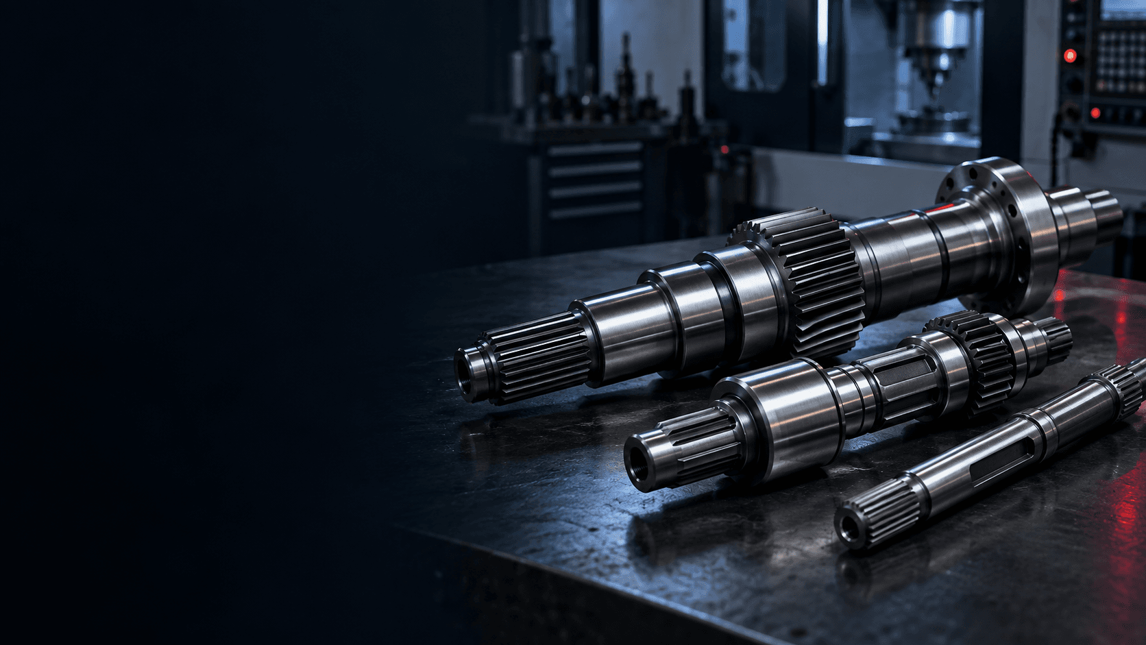
CUSTOM TRANSMISSION SHAFT MANUFACTURER
Topshaft manufactures custom input, intermediate, output and stepped transmission shafts around your drawing, torque-transfer interfaces, bearing support and critical rotational requirements.
Send your drawing, material, quantity and any torque, speed or application information for engineering review.ENGINEERING SNAPSHOT
Transmission shafts are evaluated as a complete power path: support surfaces, torque interfaces, material properties and the rotational axis work together.
POWER-TRANSMISSION ROLE
A transmission shaft is a rotating machine component designed to transfer mechanical power and torque between elements of a drivetrain or machine. It may connect or support gears, bearings, couplings, sprockets, pulleys, clutches and other rotating components.
Unlike a simple locating shaft or pin, it normally sits in the machine's power path. That means torsion, bending from mounted components and cyclic stress at shoulders, keyways and splines can all need to be considered together.
GEARBOX ARCHITECTURE
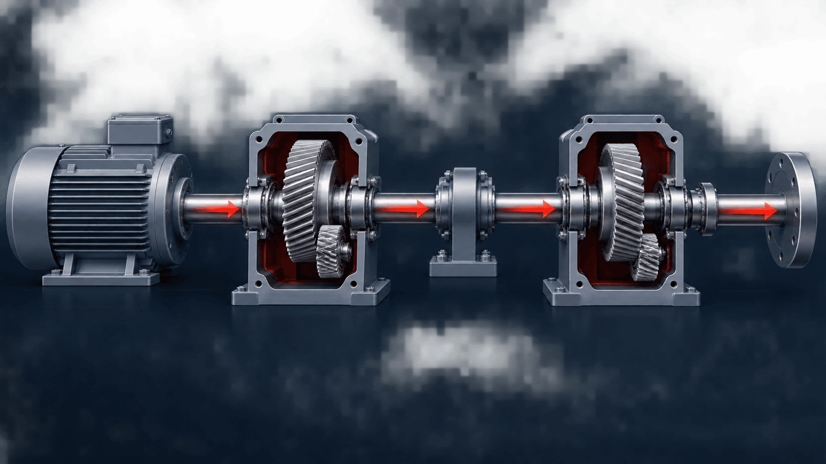
Receives torque from the motor, engine or preceding drive stage. Typical interfaces include a coupling seat, spline, keyway, gear, bearing journals and seal surfaces.
Transfers power between stages. It can carry multiple gears, bearing journals, splines, shoulders and spacers, so their relationship needs to be controlled.
Carries gears or transmission elements between input and output stages and can experience torsion plus substantial radial force from gear mesh.
Delivers torque to the driven component through a coupling, spline, pulley, sprocket, flange or another drive shaft.
LOAD PATH
Gears, pulleys, sprockets and couplings can add radial, axial and alignment loads. As the shaft rotates, these loads can create repeated stresses at the surface—so fatigue, shaft stiffness and the geometry of transitions matter alongside static strength.
STRESS-CONCENTRATION AREAS
TORQUE-TRANSFER INTERFACES
Distribute torque across multiple teeth and provide positive rotational engagement.
A familiar connection for gears, pulleys, sprockets and couplings; the keyway must match the hub and specified key.
A separate gear can locate through an interference fit, key, spline or another drawing-defined connection.
Clamping diameters, tapers, threads, splines and keyed forms connect the shaft to the next machine element.
Where the gear is part of the shaft itself, see our gear shaft and helical gear shaft manufacturing options.
Grooves, shoulders, threads and cross holes are planned around assembly position and the functional load path.
ROTATIONAL AXIS
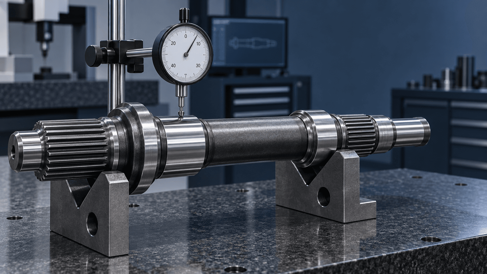
Bearings establish the shaft's rotational axis. Journal size, fit, roundness, surface finish and the relationship between bearing supports and gear or coupling seats all affect assembly, vibration and bearing loading.
MATERIAL & HEAT TREATMENT
Balanced machinability, strength and cost efficiency for general machinery applications.
A common direction where higher strength, toughness and heat-treatment capability are required.
Can be evaluated for demanding load cases that need high strength and toughness.
Selected when spline, gear or journal wear—or corrosion resistance—sets the priority.
Quenching and tempering can support core strength and toughness. Induction hardening, carburizing or nitriding can target wear-critical areas. Critical journals, seal surfaces, gear seats and coupling fits may be finish-machined or ground after treatment where the route requires it.
MANUFACTURING ROUTE
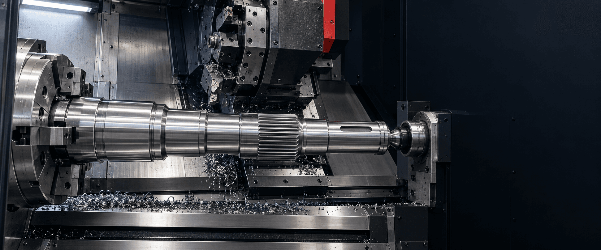
Reference diameters, bearing journals, shoulders and torque interfaces are planned around the finished shaft axis and drawing requirements.
CNC turning creates reference diameters, journals, shoulders and external profiles.
Milling and dedicated operations add keyways, splines, flats, coupling interfaces and gear seats.
Heat treatment is selected around material, duty, hardness and distortion risk.
Grinding or finish machining can be used after heat treatment for specified fits and finishes.
Inspection checks the critical relationship between bearing journals, torque interfaces and other drawing features.
Finished components are cleaned, protected and prepared to the agreed packaging and documentation requirement.
QUALITY CONTROL
Inspection focuses on the characteristics that affect bearing fit, torque transfer, alignment and assembly compatibility.
| Bearing journal diameter | Correct bearing fit |
|---|---|
| Journal runout | Stable rotation |
| Gear / coupling seat runout | Alignment with transmission axis |
| Spline & keyway dimensions | Correct torque-transfer interface |
| Straightness & shoulder location | Assembly alignment and axial positioning |
| Surface roughness & hardness | Wear and specified treatment result |
APPLICATION CONTEXT
High-torque, lower-speed shafts often focus on torsional strength, spline or keyway capacity, material and treatment. High-speed shafts can require additional attention to runout, straightness, mass distribution, surface finish, balance and critical-speed behaviour.
A transmission shaft is the broader gearbox and machinery power-transmission component. A drive shaft more often connects separate drive components.
Explore custom drive shafts →A gear shaft has an integral gear feature. A transmission shaft may carry a separate gear on a spline, key or interference-fit seat.
Explore custom gear shafts →PREPARE YOUR RFQ
Share the information that helps us evaluate shaft geometry, bearing interfaces, torque-transfer features, material, heat treatment and critical tolerances before quotation.
BUYER QUESTIONS
A transmission shaft is a rotating component that transfers mechanical power and torque between machine or drivetrain elements. It may also support gears, bearings, pulleys, sprockets or couplings.
Common features include bearing journals, splines, keyways, threads, gear and coupling seats, grooves, shoulders, flats and holes.
Yes. Where the drawing requires it, cylindrical grinding can be used to achieve tighter diameter, roundness or surface-finish requirements on critical journals.
Depending on material and application, the route can include quenching and tempering, induction hardening, carburizing, nitriding or another specified treatment.
The terms can overlap. Here, a transmission shaft means the broader gearbox and machinery power-transmission component, while a drive shaft is usually a connecting torque-transfer shaft between separate components.
Send the drawing or CAD model, material, heat treatment, quantity and critical tolerances. Power, speed, peak torque and application information are also useful when available.
READY TO START?