
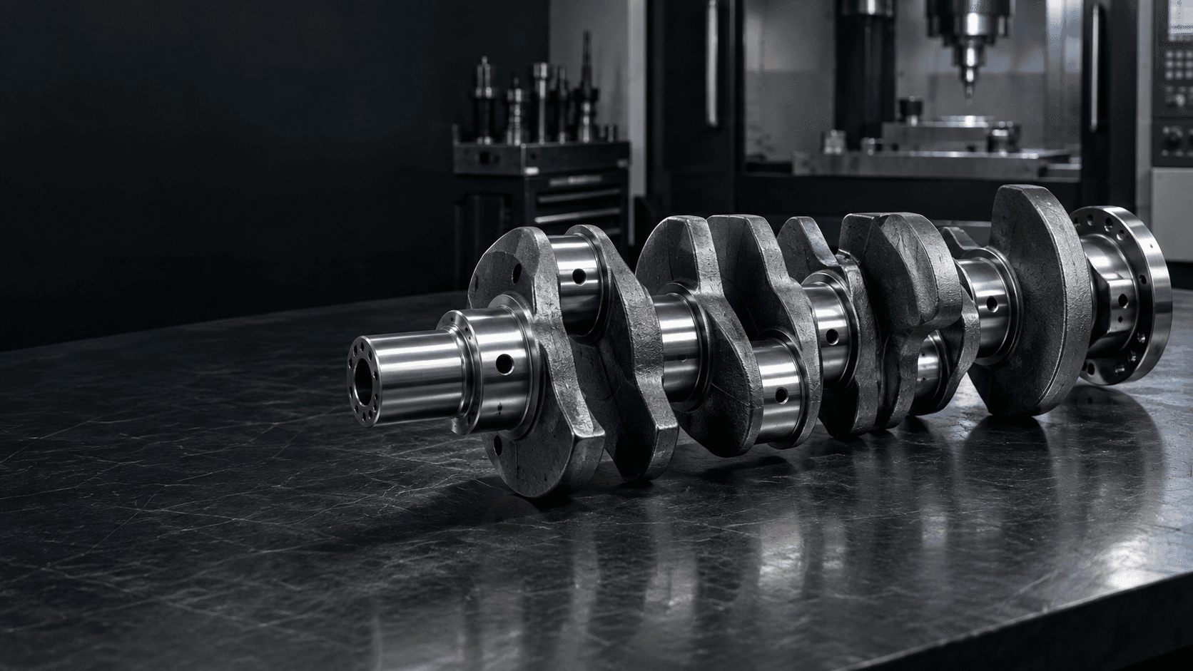
CUSTOM CRANKSHAFT MANUFACTURER
Custom
Crankshafts
Precision journals. Controlled throw. Reliable motion conversion.
Custom crankshafts with precision-controlled main journals, crankpins, throw geometry and fatigue-critical surfaces for engines, compressors and industrial reciprocating machinery.We review the main axis, offset geometry, phase relationships, materials and inspection requirements around your drawing.
For multi-throw crankshafts, include crankpin phase angles and complete journal datum requirements.CRANKSHAFT ENGINEERING SNAPSHOT
Offset geometry must work as one motion system.
The main journals establish the axis; the crankpins, webs and counterweights define the mechanism around it.- Core mechanism
- Main journals, offset crankpins and crank webs converting rotary and reciprocating motion
- Critical geometry
- Crank throw, crankpin phase, journal alignment and web relationships
- Functional surfaces
- Main journals, rod journals, thrust faces, oil passages and drive interfaces
- Manufacturing
- Turning, offset crankpin machining, drilling, heat treatment and journal grinding
- Load priorities
- Cyclic bending, torsion, fatigue-sensitive fillets and balance requirements
- Inspection
- Main axis, journal form, throw, phase, parallelism and drawing-defined documentation
WHAT IS A CRANKSHAFT?
A structured mechanism—not simply an eccentric shaft.
A crankshaft connects one or more offset crankpins to a main rotational axis through crank webs. Connecting rods mounted on those crankpins convert linear reciprocating motion and rotary motion in engines, compressors, pumps and special machinery.
Its critical geometry is the relationship among the main journals, crankpin offsets, axial locations and phase angles—not one isolated diameter.
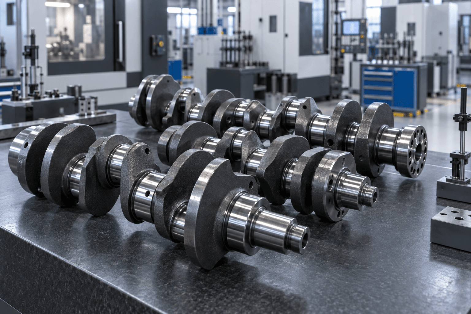
CRANKSHAFT ANATOMY
What are the main functional features?
Crankpins
Offset rod journals that create the crank throw and connect to rods.Crank webs
Structural links between journals and crankpins that transmit load.Fillet transitions
Fatigue-sensitive geometry between journals and webs.Counterweights
Drawing-defined mass geometry that can manage rotating and reciprocating forces.Oil passages
Internal routes that deliver lubricant to journal and crankpin interfaces.MANUFACTURING ROUTE
How is a custom crankshaft manufactured?
The sequence is selected to preserve the main axis and specified offset geometry through machining, treatment and final finishing.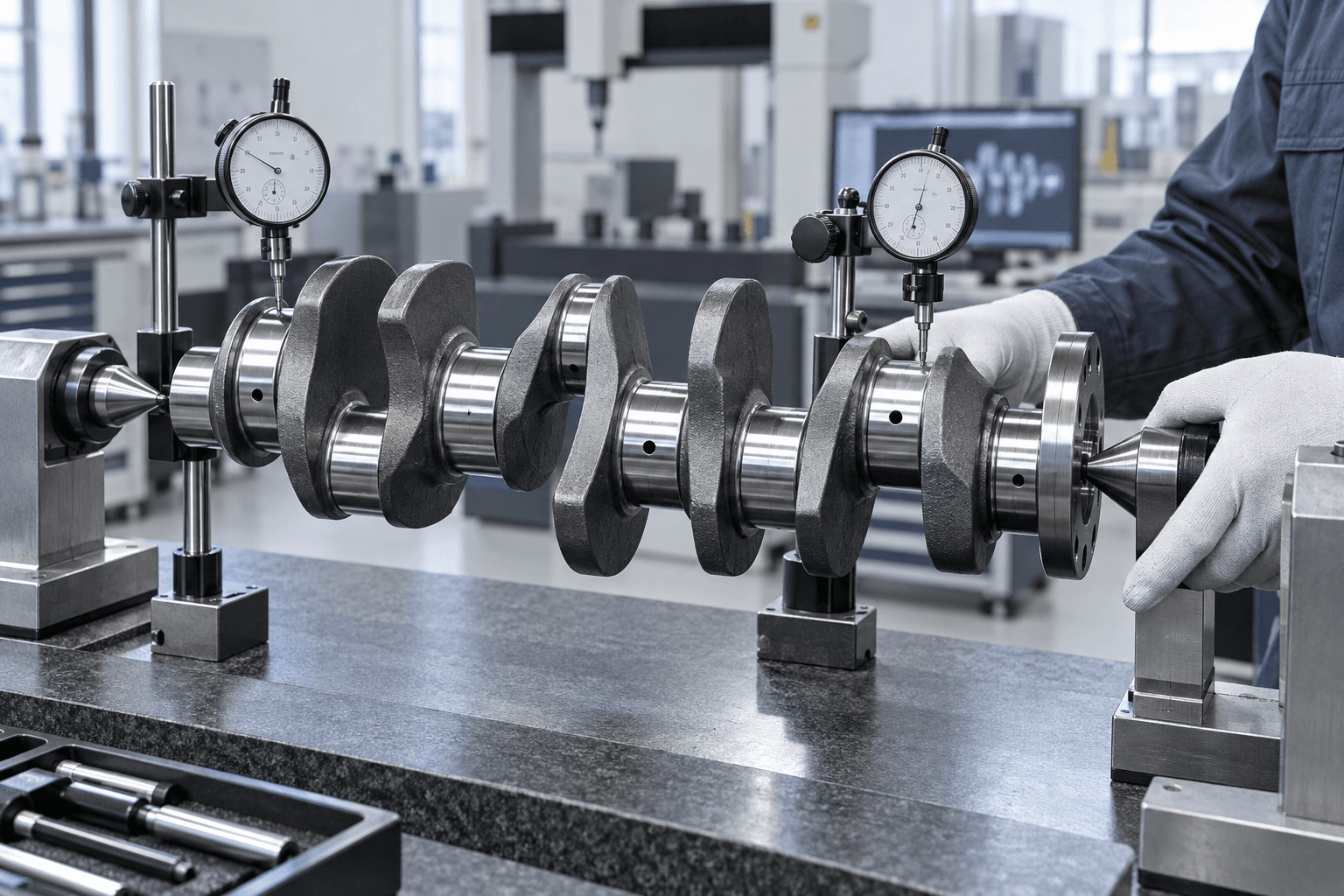
JOURNALS, THROW AND PHASE
A correct journal diameter is only one part of the result.
Main journals need a common rotational reference. Crankpins also need their specified offset, axial location, parallelism and phase relationship to produce the intended mechanism motion.- Main-journal diameter, roundness, taper and alignment
- Crankpin diameter, width, offset and axial position
- Crank throw and phase-angle relationships for multi-throw designs
- Journal-to-web fillet geometry and relevant thrust surfaces
- Oil-hole location, surface condition, hardness and balance requirements where specified
FATIGUE AND ROTATIONAL BEHAVIOR
Webs, fillets and counterweights are functional geometry.
Crankshaft loading is typically cyclic. Journal-to-web fillets, reduced sections and oil-hole areas can be particularly important; counterweight geometry and balance may also need review for the intended operating conditions.Forged, cast or billet
The most appropriate starting route depends on the drawing, quantity, required fatigue performance, material and the complete manufacturing plan.
Grinding after treatment
Final grinding can be used on main journals and crankpins where the drawing requires controlled diameter, roundness, taper or surface finish after treatment.
APPLICATION CONTEXT
Where are custom crankshafts used?
Engine systems
Gasoline, diesel, generator and special-purpose engine crank mechanisms.Compressors
Rotary-to-reciprocating mechanisms for piston compressors.Reciprocating pumps
Crank-driven pump and plunger systems.Test equipment
Repeatable motion and load generation for engineering test rigs.Industrial machinery
Custom slider-crank mechanisms for production equipment.Replacement projects
Drawing-based manufacture for industrial repair and legacy equipment.RELATED SHAFT TYPES
Motion-conversion geometry has its own requirements.
Crankshaft vs. Eccentric Shaft
An eccentric shaft uses offset cylindrical sections. A crankshaft uses crankpins and webs connected to a main rotational axis, often across multiple throws.Explore →Crankshaft vs. Camshaft
Crankshafts generate reciprocating-to-rotary motion through offset crankpins; camshafts create programmed follower movement through lobe profiles.Explore →Crankshaft vs. Transmission Shaft
A transmission shaft transfers power through a drivetrain. A crankshaft is a motion-conversion mechanism with throw and phase geometry.Explore →Crankshaft vs. Stepped Shaft
Stepped shaft describes multiple diameter geometry. Crankshaft adds offset crankpins, webs and a defined motion relationship.Explore →PREPARE YOUR RFQ
What is needed for a crankshaft quote?
Complete crank geometry and functional data supports a practical manufacturing review.- 01Overall length, number of throws and complete main-journal geometry
- 02Crankpin diameters, widths, axial positions and crank throw
- 03Crankpin phase angles, web dimensions and counterweight geometry
- 04Oil passages, thrust surfaces, keyways, splines, threads and flanges
- 05Journal tolerances, runout, straightness, parallelism, phase and GD&T
- 06Material, blank type, heat treatment, hardness and finishing requirements
- 07Prototype or production quantity and required inspection documentation
CRANKSHAFT FAQS
Common engineering questions.
Practical guidance for teams sourcing custom crankshaft components.What is a crankshaft?+
A crankshaft is a rotating shaft with one or more offset crankpins that converts reciprocating motion into rotation, or rotation into reciprocating movement.
What is a crankshaft main journal?+
A main journal is a concentric cylindrical surface supported by the main bearings. The main journals establish the crankshaft's primary rotational axis.
What is a crankpin?+
A crankpin, also called a rod journal, is an offset journal that connects with a connecting rod. Its offset from the main axis creates the crank throw.
How does crank throw affect stroke?+
For a conventional centered slider-crank mechanism, total piston or follower stroke is twice the crank radius. The required throw should be defined directly on the drawing.
Why are crankshaft fillets important?+
Journal-to-web fillets are fatigue-sensitive transitions under cyclic bending and torsional load. Their geometry must balance stress control with clearance and manufacturing requirements.
Can Topshaft evaluate multi-throw crankshafts?+
Multi-throw projects can be evaluated from the drawing, number of throws, crankpin positions, phase angles, material, heat treatment and tolerance requirements.
READY TO START?