
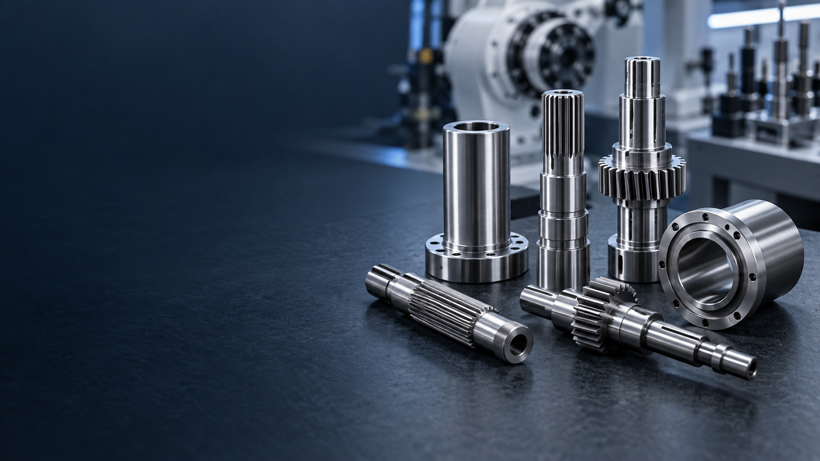
ROBOTICS SHAFT MANUFACTURING
Robotics Precision,
Made For Controlled Motion.
Custom motor, hollow, gear, spline, joint and motion shafts manufactured around the bearing, reducer, routing, weight and precision requirements of robotic systems.JOINTS / ACTUATORS / BORES / SPLINES / GRINDINGROBOTICS SHAFT ENGINEERING SNAPSHOT
Precision Components
For Controlled Motion.
TOPSHAFT manufactures custom precision shaft components used inside robotic systems. We focus on the shaft interfaces that support motor, bearing, reducer, routing and output requirements—not on complete robot joints, reducers or robots.| Capability | TOPSHAFT support |
|---|---|
| Manufacturing focus | Custom precision shafts for robot joints, actuators, servo systems, reducers, wrists and linear axes |
| Shaft roles | Motor, hollow, gear, spline, output, wrist, joint and linear-motion shaft components |
| Functional geometry | Bearing journals, rotor seats, bores, splines, gears, shoulders, threads and encoder interfaces |
| Critical controls | Runout, journal alignment, bore concentricity, straightness, fits, surface finish and hardness |
| Processes | CNC turning and milling, bore machining, gear/spline features, heat treatment, grinding and inspection |
| Project support | Prototype, first article, pilot and repeat OEM production around approved drawings |
PRECISION SHAFT SOLUTIONS FOR ROBOTICS
Designed Around
The Robot Axis.
A robotic axis combines multiple components. The shaft must be considered around its bearing supports, motor or reducer connection, output relationship, routing path and drawing-defined tolerance chain.ROBOTICS SHAFT APPLICATIONS AT A GLANCE
Match The Shaft
To The Axis.
Application context helps establish the right shaft architecture and functional measurement plan.| Robotics application | Typical shaft configuration | Key requirements |
|---|---|---|
| Industrial robot joint | Joint / output shaft | Bearing alignment, reducer interface, runout |
| Collaborative robot | Compact joint or hollow shaft | Mass, routing, controlled interfaces |
| Humanoid joint | Motor, reduction and output shaft | Compactness, stiffness, packaging |
| Robot wrist | Small hollow or stepped shaft | Routing, concentricity, end-effector fit |
| Servo actuator | Motor / rotor shaft | Bearing fit, rotor runout, encoder interface |
| Reducer stage | Gear or spline shaft | Torque interface, gear-to-journal relationship |
| SCARA robot | Rotary-axis shaft | Bearing alignment, repeatable rotation |
| Cartesian robot | Linear-motion shaft | Straightness, surface and support geometry |
| End effector | Output / coupling shaft | Tool interface and load transfer |
ROBOT JOINT ARCHITECTURE
One Motion Axis.
A Controlled Stack.
Precision shaft interfaces support alignment and fit requirements of low-backlash robotic drivetrains. The complete joint is a system-level assembly; the component drawing defines TOPSHAFT's shaft scope.Encoder / Feedback → Servo Motor → Motor / Rotor Shaft → Reducer → Gear / Spline Interface → Output Bearing → Joint / Hollow Output Shaft → Next Robot Link
Functional shaft interfaces
- Bearing journals establish the supported rotation axis
- Motor and rotor seats locate actuator components
- Splines and gears transfer torque to reducer stages
- Hollow bores can support routing through the axis
- Shoulders and threads control axial location and retention
WHAT MAKES A ROBOTICS SHAFT DIFFERENT?
Interfaces Matter
As Much As Diameter.
Robot shafts commonly link bearing, motor, reducer, routing and output functions in compact space. The relevant datums and CTQs should follow the actual axis assembly rather than isolated nominal dimensions.Engineering focus
- Compact packaging around multiple interfaces
- Controlled fit and alignment relationships
- Torque transfer, routing and weight requirements
HUMANOID & COBOT SHAFTS
Compact Motion
Needs Context.
Humanoid and collaborative robots can place high value on packaging, mass, routing and repeatability. TOPSHAFT evaluates the shaft component from its drawing, not the complete robot design.Useful project inputs
- Axis role, bearing arrangement and motor/reducer interface
- Hollow-bore routing requirements
- Mass, stiffness and load information where available
CRITICAL ROBOTICS SHAFT CHARACTERISTICS
Inspect The Features
That Support The Axis.
Robot positioning accuracy is a system-level result, but shaft and bearing-interface geometry contribute to the mechanical joint tolerance chain. Select controls that represent the customer's actual functional datum structure.| CTQ | Why it matters |
|---|---|
| Bearing journal diameter | Controls bearing fit |
| Journal-to-journal alignment | Defines the mechanical rotating axis |
| Runout | Controls variation of a rotating feature relative to datum axis |
| Straightness | Supports controlled rotating or linear behavior |
| Rotor seat | Controls rotor or motor-component fit |
| Spline fit | Transfers torque through the required interface |
| Gear-to-journal alignment | Supports reducer and drivetrain geometry |
| Hollow-bore concentricity | Supports routing and wall consistency |
| Wall thickness | Maintains hollow-section design intent |
| Shoulder position | Controls axial component location |
| Surface roughness | Supports fit, wear and bearing requirements |
| Hardness | Supports wear and fatigue requirements |
| Thread / interface geometry | Defines assembly and retention features |
STIFFNESS VS. WEIGHT
Balance The
Load Path.
Stiffness and mass are linked design choices. Shaft geometry should be evaluated within the complete bearing span, torque path, acceleration profile, external loads and packaging envelope.Consider
- Axis acceleration and transmitted torque
- Bending length, bearing spacing and output load
- Wall thickness and bore geometry for hollow designs
HOLLOW BORE & CABLE ROUTING
Route Through
The Rotational Axis.
A central bore can simplify routing through a rotational axis and reduce the need for external cable loops. Bore size, wall thickness, concentricity and surface requirements should be explicit on the drawing.Review points
- Routing type: cable, pneumatic or fluid pathway
- Bore-to-OD relationship and inspection datum
- Changes in stiffness, treatment and machining route
MATERIALS FOR ROBOTICS SHAFTS
Chosen For The
Functional Requirement.
Material selection follows the customer's torque, fatigue, wear, corrosion, mass, treatment and operating requirements. The final grade and condition should be stated on the drawing.Discuss Your Material Requirement →| Material | Typical direction | Engineering reason |
|---|---|---|
| 1045 / C45 | General joint and motion shafts | Strength and machinability |
| 4140 / 42CrMo | Higher-load drivetrain shafts | Strength and toughness |
| 17-4PH | Precision or corrosion-sensitive applications | Strength with corrosion resistance |
| 304 / 316 stainless | Corrosive or clean environments | Corrosion resistance |
| Aluminum alloys | Lightweight structures | Reduced mass |
| Titanium | Weight-critical specialized designs | Strength-to-weight direction |
| Customer-specified alloy | Drawing-led programs | Specified functional requirement |
HEAT TREATMENT & SURFACE CONDITION
Plan The Thermal Route
Around Functional Fits.
Critical journals, splines, gears and mating surfaces may require a controlled sequence of machining, thermal processing and final grinding where specified.Potential routes
- Quenching and tempering for suitable alloy steels
- Induction hardening on selected wear surfaces
- Nitriding for compatible steel grades
- Age hardening for precipitation-hardening stainless steel
- Stress relieving where dimensional stability is required
RUNOUT & JOINT-AXIS RELATIONSHIP
Control The
Relevant Datum Axis.
Runout measures variation of a rotating surface relative to a defined datum axis. Gear, spline, bore and output requirements should reference the axis that represents the assembly function.Drawing review questions
- Which journal or datum axis controls the function?
- Which surfaces require grinding or fine finish?
- How are bore, gear and spline relationships measured?
ROBOTICS SHAFT MANUFACTURING PROCESSES
Linked Processes
For Compact Geometry.
Turning, bore machining, milling, gear or spline work, treatment and grinding are planned as one process chain around approved geometry and inspection requirements.CNC Turning
Journals, shoulders, stepped geometry, grooves, threads and output sections.
Swiss Turning
Small-diameter or slender precision shaft geometries.
Multi-Axis CNC Milling
Flats, slots, holes, keyways and complex interfaces.
Deep-Hole / Bore Machining
Controlled hollow sections and routing bores.
Gear & Spline Machining
Torque-transfer and reducer interfaces.
Precision Grinding
Selected critical journals, bores, rotor fits and precision surfaces.
FROM ROBOTICS DRAWING TO PRODUCTION SHAFT
Build The Route
Around The Interfaces.
Projects are reviewed around customer drawings, critical datums, interfaces, material, treatment, precision, inspection and commercial requirements. Final system performance is validated by the customer in the complete robot assembly.- 01Robot Axis & Drawing ReviewPlanned around the drawing and confirmed project requirements.
- 02Identify Bearing, Reducer & Motor InterfacesIdentify functional relationships among bearing, motor, reducer, bore and output interfaces.
- 03Define Datums & CTQsPlanned around the drawing and confirmed project requirements.
- 04CNC Shaft & Bore MachiningPlanned around the drawing and confirmed project requirements.
- 05Gear, Spline & Secondary FeaturesPlanned around the drawing and confirmed project requirements.
- 06Heat TreatmentPlanned around the drawing and confirmed project requirements.
- 07Precision GrindingPlanned around the drawing and confirmed project requirements.
- 08Runout, Bore & Interface InspectionInspect drawing-specified geometry, runout, bore, surface and interface features.
- 09Prototype Validation & Repeat ProductionPlanned around the drawing and confirmed project requirements.
Axis review → Datums & CTQs → Process plan → Machining → Treatment → Grinding → Inspection
FROM PROTOTYPE TO PRODUCTION
Support The
Development Path.
Robotics projects can move from initial geometry review to a repeatable approved component process while the customer validates the shaft in its complete system.Typical project stages
- Prototype: confirm geometry and assembly intent
- First article: validate CTQs and inspection approach
- Customer system validation: verify robot-axis performance
- Pilot batch: confirm process repeatability
- Production: maintain approved requirements across repeat orders
ROBOTICS SHAFT QUALITY CONTROL
Measure The
Functional Geometry.
Inspection methods are selected around the drawing and agreed project requirements.Possible inspection controls
- Journal, bore, shoulder, spline, gear, thread and interface dimensions
- Runout, straightness and selected axis relationships
- Surface roughness, hardness and drawing-specific documentation
- Material and processing certificates where agreed
DFM FOR ROBOTICS SHAFTS
Define The Functional
Interfaces Early.
Useful DFM information helps focus manufacturing controls where they affect the robot axis rather than applying unnecessary precision to nonfunctional surfaces.Helpful inputs
- Identify bearing, motor, reducer and output interfaces
- Define reference datums for runout and bore relationships
- State material, treatment, hardness and ground surfaces
- Provide load, speed or routing context where available
- Consider assembly sequence and access for inspection
WHY TOPSHAFT FOR ROBOTICS SHAFTS
Robotics Context,
Shaft-Focused Delivery.
TOPSHAFT combines drawing-led component manufacturing with review of the shaft's practical role inside robotic motion systems.Project approach
- Review motor, bearing, reducer, routing and output interfaces together
- Support compact hollow, splined, geared and stepped shaft requirements
- Manufacture and inspect to approved drawing requirements
- Support prototype, first article, pilot and repeat OEM production
WHAT INFORMATION IS NEEDED FOR A ROBOTICS SHAFT PROJECT?
Send The Data That
Defines The Axis.
Complete geometry, interface, precision, material and quantity information enables a more useful engineering review.Upload Your Robotics Shaft Drawing →| Information group | Include where available |
|---|---|
| Application & axis role | Robot type, joint, wrist, actuator, reducer, SCARA, Cartesian or end-effector role |
| Shaft geometry | Overall length, journals, bore, shoulders, splines, gears, threads and interfaces |
| Mating interfaces | Bearing, motor/rotor, reducer, output and routing requirements |
| Precision requirements | Fits, runout, straightness, surface roughness, GD&T and inspection datum |
| Material & treatment | Material grade, heat treatment, hardness and surface treatment |
| Commercial requirements | Prototype and production quantity, annual demand, documentation and delivery |
RELATED ROBOTICS SHAFT SOLUTIONS
Follow The Motion
Architecture.
01Motor ShaftServo and rotor interfaces→02Hollow ShaftThrough-bore geometry→03Gear ShaftReducer interfaces→04Helical Gear ShaftHelical transmission features→05Spline ShaftTorque-transfer splines→06Stepped ShaftMulti-diameter joint geometry→07Spindle ShaftPrecision rotary systems→08Linear Motion ShaftAutomation-axis components→09Motor IndustryMotor-system context→10Gearbox IndustryReducer-system context→11Medical IndustryPrecision automation context→
View All Precision Shaft Products →ROBOTICS SHAFT FAQS
Answers For The
Axis Drawing Review.
Practical questions for robotics engineers, OEM procurement teams and automation-system buyers.What shafts are used in robotics?+
Robotic systems can use motor, rotor, hollow, gear, spline, output, wrist, stepped and linear-motion shafts. The correct type follows the joint, actuator, reducer, bearing and routing architecture.
Does TOPSHAFT manufacture complete robot joints or reducers?+
No. TOPSHAFT manufactures custom precision shaft components to the approved drawing. Complete robot joints, harmonic drives, reducers and robots are system-level products supplied by their respective manufacturers.
Why are hollow shafts used in robot joints?+
A central bore can simplify routing through a rotational axis and reduce the need for external cable loops. The bore, wall thickness and concentricity should be defined around the actual system requirements.
Why does robot joint runout matter?+
Robot positioning accuracy is a system-level result, but shaft and bearing-interface geometry contribute to the mechanical joint tolerance chain. Runout is specified relative to the datum axis that reflects the assembly function.
Can robot shafts include splines or gears?+
Yes. Drawing-specified spline, gear, pinion, keyway and other torque-transfer features can be reviewed as part of a custom shaft component.
Can TOPSHAFT make hollow shafts with splines?+
Projects with hollow bores, splines and external functional features can be reviewed around material, wall thickness, datums, manufacturing sequence and inspection requirements.
What materials are used for robotics shafts?+
Carbon steels, alloy steels, stainless steels, aluminum, titanium and customer-specified alloys may be selected according to load, wear, corrosion, mass, treatment and drawing requirements.
Can bearing journals be precision ground?+
Where specified, final grinding can control selected bearing journals, fits and precision surfaces after machining or thermal processing.
How do stiffness and weight affect a robotics shaft?+
They are related engineering tradeoffs. The required shaft geometry depends on the complete load path, bearing span, torque, packaging, acceleration and dynamic system requirements.
Can you support prototype and repeat production?+
Projects can be reviewed from prototype and first article through pilot quantities and repeat OEM production based on the approved drawing and commercial requirements.
What inspection data can be discussed?+
Drawing-specified dimensional results, runout, surface, hardness, material and agreed documentation requirements can be reviewed during quotation and project planning.
Can TOPSHAFT support servo and actuator shafts?+
Servo and actuator shaft projects can be reviewed around bearing, rotor, encoder, output, speed and critical geometry requirements.
Can you advise on robot shaft DFM?+
TOPSHAFT can review manufacturability around the supplied drawing, functional datums, material, tolerances and practical process route. Final robot-system design responsibility remains with the customer.
What is needed for a robotics shaft quotation?+
Please provide the drawing or CAD, application and axis role, material, bearing/motor/reducer interfaces, CTQs, quantity, documentation and delivery requirements.
NEED A CUSTOM ROBOTICS SHAFT?