
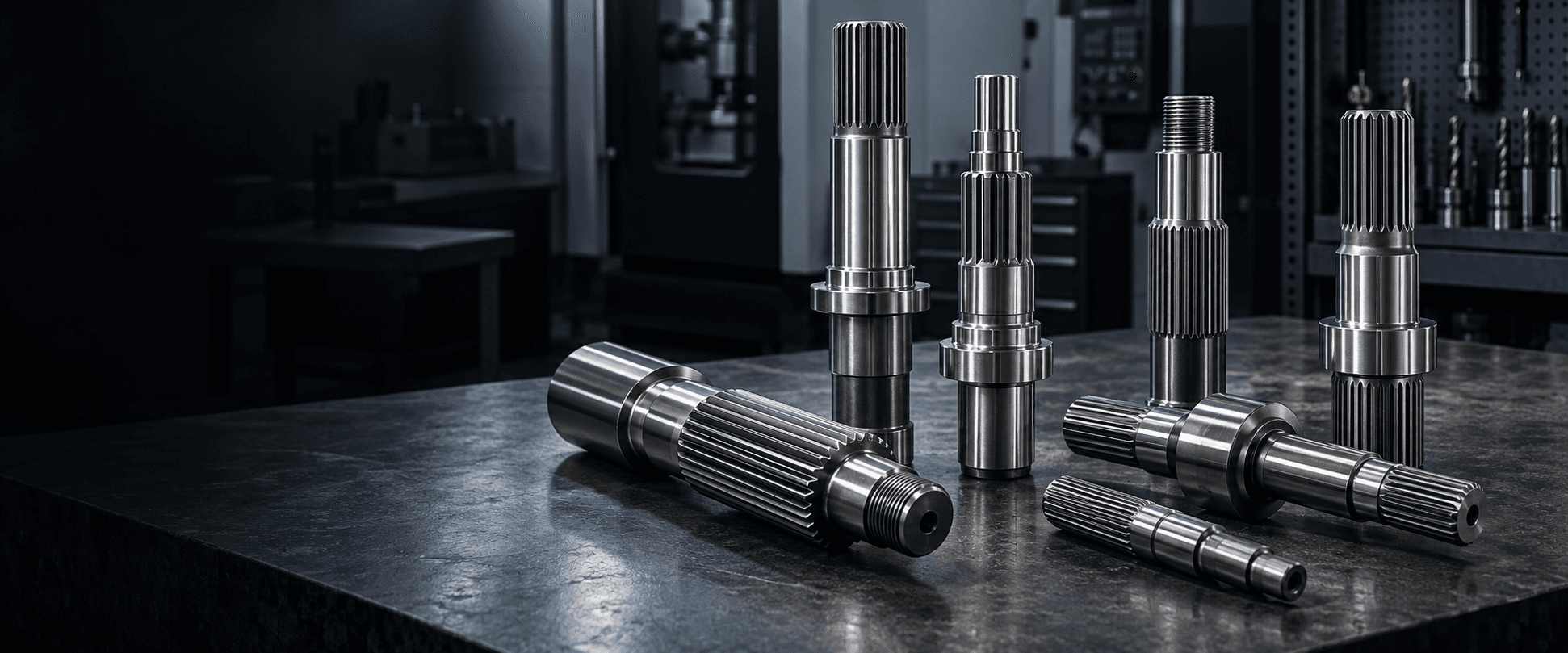
PRECISION SPLINE SHAFT MANUFACTURING
Custom Spline
Shaft
Multiple teeth. Controlled fit. Reliable torque transfer.
Custom precision spline shafts with controlled tooth geometry, spline fit and shaft alignment for gearboxes, motors and industrial power-transmission systems.We review the spline profile, mating function, bearing journals, material, heat treatment and inspection requirements around your drawing.
Include the applicable spline standard and complete spline designation whenever available.SPLINE SHAFT ENGINEERING SNAPSHOT
Fit and alignment are as important as the tooth shape.
A spline connection is a functional interface between shaft and hub—not merely an outside diameter with teeth.- Spline types
- Involute, straight-sided and drawing-defined profiles
- Functional focus
- Tooth-flank engagement, fit, centering and torque transfer
- Critical controls
- Spline-to-journal alignment, runout and usable engagement length
- Manufacturing
- Turning, spline cutting, heat treatment, finishing and inspection
- Applications
- Gearboxes, motors, drives and industrial power transmission
- Inspection
- Functional gauges, tooth measurement and datum-based checks
WHAT IS A SPLINE SHAFT?
Torque transfer through multiple controlled tooth flanks.
External spline teeth engage with an internal spline hub. The contact surfaces can transfer torque across multiple teeth while supporting a coaxial shaft-to-hub relationship.
The right profile and fit depend on whether the connection is fixed or sliding, the torque and reversing load, required engagement length, wear conditions and surrounding shaft geometry.
SPLINE PARAMETERS
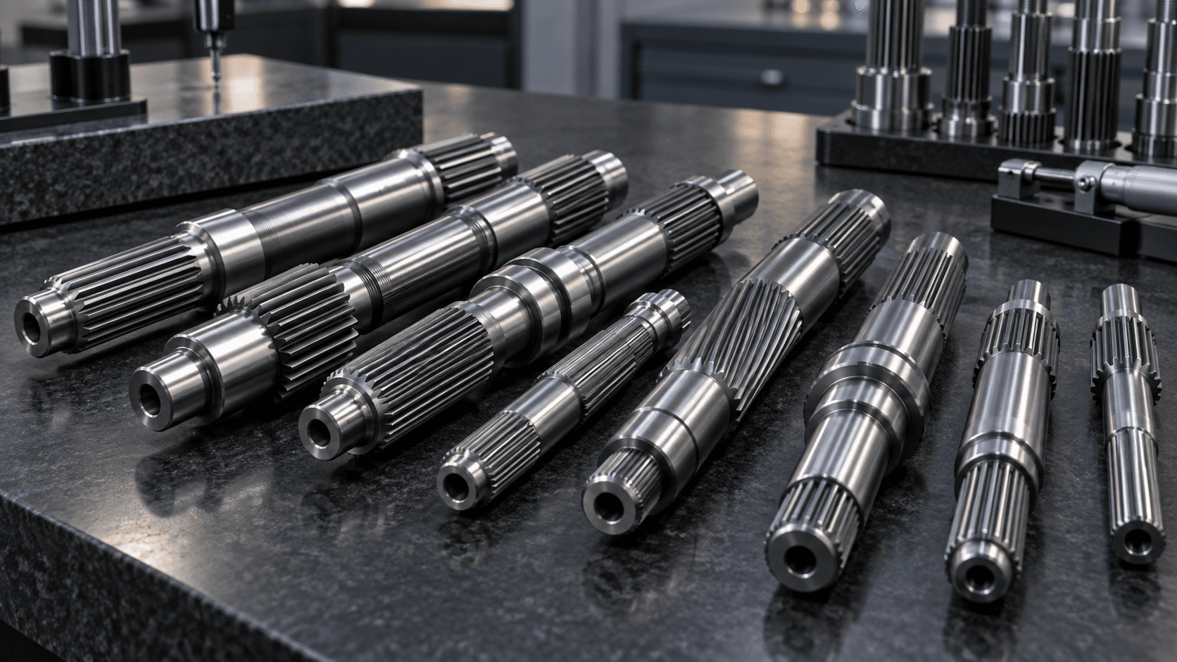
What defines a custom spline connection?
Tooth geometry
Tooth count, module or pitch, pressure angle, major and minor diameters.Spline fit
Tooth thickness, space width and the functional clearance or interference requirement.Engagement length
Usable full-tooth length distinguished from relief or tool-runout zones.Connection type
Fixed or sliding, because axial motion changes wear and lubrication considerations.Rotational datum
Spline-to-journal alignment and runout relative to the operating axis.MANUFACTURING ROUTE
How are spline shafts manufactured?
The specific method is selected after reviewing the spline standard, size, tolerance, material and surrounding shaft features.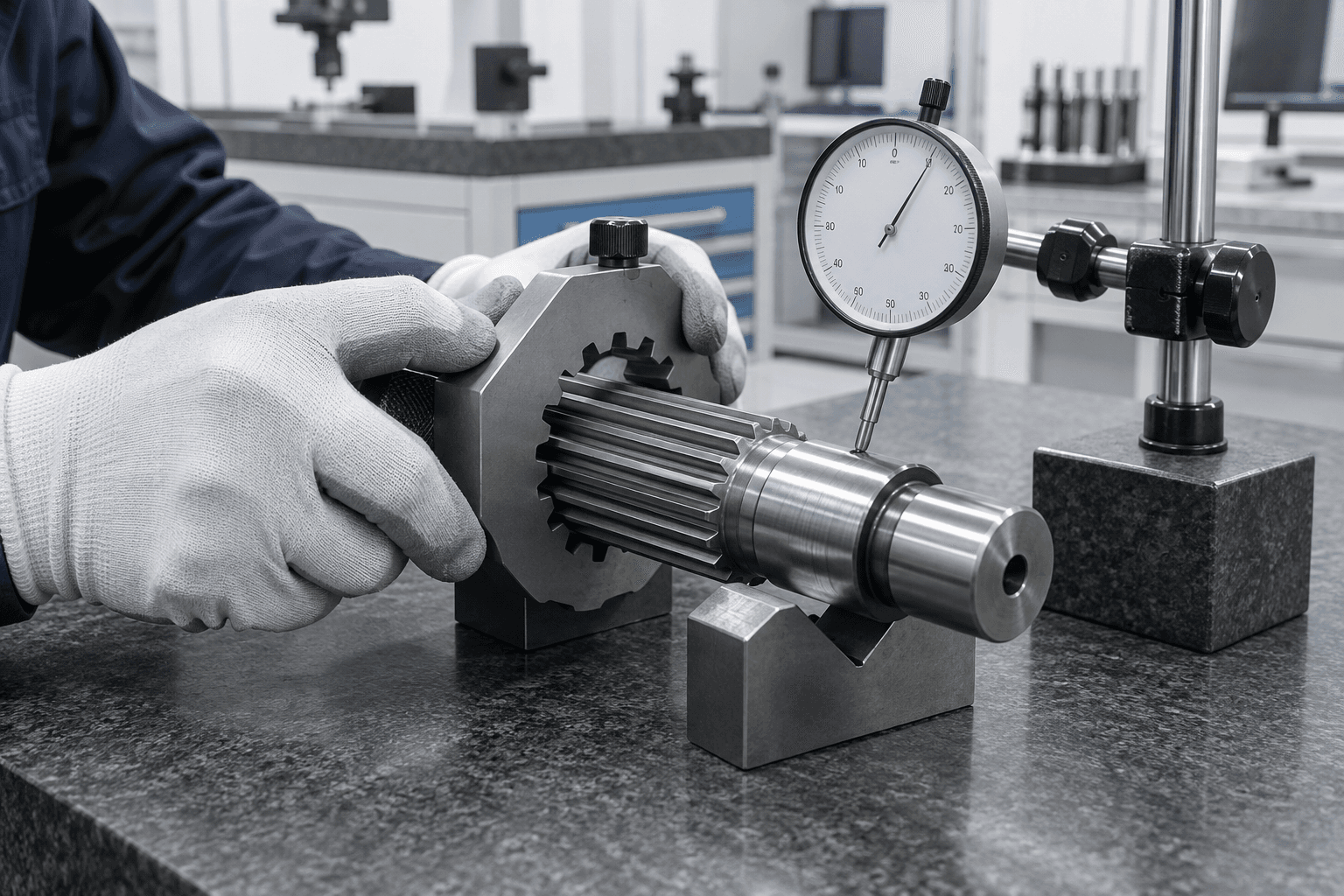
SPLINE FIT AND INSPECTION
A correct spline profile must also assemble correctly.
Inspection can focus on engagement itself and how the spline is positioned relative to bearing journals, shoulders and the intended rotation axis.- Tooth count, major and minor diameters
- Tooth thickness, space width and functional fit
- Usable full-tooth engagement length and relief
- Spline runout and spline-to-journal alignment
- Surface finish, hardness and drawing-defined documentation
FIXED OR SLIDING
One spline profile can serve different functional roles.
Fixed splines transfer torque in one axial position. Sliding splines transfer torque while allowing axial movement, making fit, friction, lubrication and wear particularly important.Involute vs. straight-sided
Involute splines use curved tooth flanks; straight-sided splines use parallel-sided teeth. They require complete and distinct geometry definitions.
Spline vs. gear shaft
A spline connects a shaft to a hub at the same ratio. Gear teeth mesh with another gear to transmit power through a gear pair.
APPLICATION CONTEXT
Where are spline shafts used?
Gearboxes
Torque transfer between gearbox components and hubs.Electric motors
Motor output and rotor-side transmission interfaces.Industrial drives
Fixed or sliding connections in machinery drives.Automation
Compact torque connections for actuators and equipment.Construction equipment
Durable power-transfer components under cyclic load.Agricultural machinery
Splined interfaces across implements and drivetrains.Pumps & machinery
Rotary transmission with shaft-to-hub engagement.Custom OEM systems
Drawing-specific splines combined with other shaft features.RELATED PRODUCTS
Choose the connection by function.
Spline Shaft vs. Gear Shaft
Spline teeth engage a mating hub; gear teeth mesh with another gear and can change torque or speed.Explore →Spline Shaft vs. Transmission Shaft
A spline may be one interface on a transmission shaft; transmission shaft describes the broader power-transfer role.Explore →Spline Shaft vs. Keyed Shaft
Both can transfer torque. Splines use multiple tooth surfaces and can support fixed or sliding configurations.Explore →Spline Shaft vs. Motor Shaft
A motor shaft may include a spline when the output interface needs controlled torque engagement.Explore →PREPARE YOUR RFQ
What is needed for a spline shaft quote?
Complete spline and shaft data supports a useful manufacturing review.- 01Spline type and applicable standard
- 02Tooth count, module / pitch and pressure angle
- 03Major, minor and pitch diameters
- 04Spline length and usable engagement length
- 05Fit or tolerance class; fixed or sliding function
- 06Bearing journals, runout and GD&T
- 07Material, heat treatment and surface requirements
- 08Quantity and required inspection documentation
BUYER QUESTIONS
Spline shaft FAQs
Practical answers for transmission and sourcing teams.What is a spline shaft?+
A spline shaft has multiple longitudinal teeth that engage a mating internal spline to transmit torque while maintaining a coaxial shaft-to-hub connection.
What is an involute spline?+
An involute spline uses involute tooth flanks. A complete drawing or spline designation is needed to define its geometry and fit.
Can a spline shaft move axially?+
Yes. A sliding spline is designed to transmit torque while allowing axial movement; a fixed spline connection has different fit and wear requirements.
How are splines inspected?+
Depending on the requirement, inspection may use functional gauges, tooth measurements, span measurement, profile inspection or datum-based checks.
What should I send for quotation?+
Please send the 2D drawing, 3D model where available, spline standard or full designation, fit, material, heat treatment, critical GD&T and quantity.
READY TO START?