Keep the rotation centred
Variation perpendicular to the spindle axis can affect tool position, hole accuracy, surface finish and vibration.

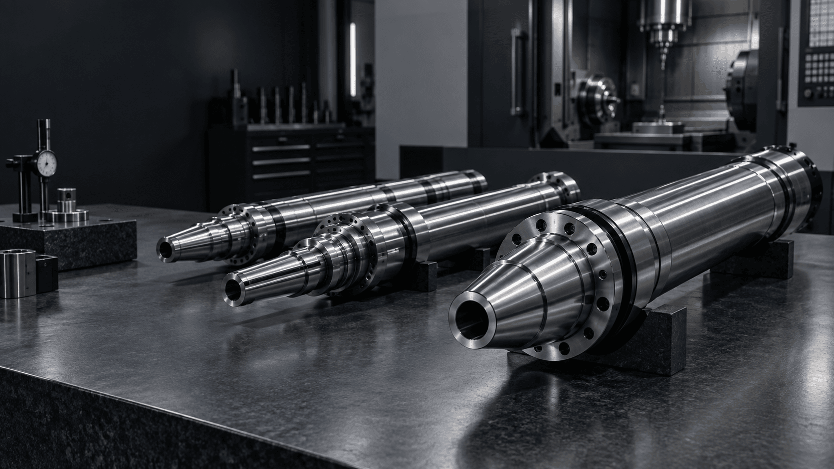
CUSTOM SPINDLE SHAFT MANUFACTURER
Topshaft manufactures custom spindle shafts for machine tools, grinding equipment, CNC machinery and high-accuracy rotating equipment—made to your drawing with controlled bearing seats, nose geometry and runout requirements.
Include bearing fits, critical runout, taper or nose geometry, material and operating speed where available.ENGINEERING SNAPSHOT
A spindle does more than transmit torque. It supports precision bearings and establishes the working axis of the machine under speed, load and thermal change.
SPINDLE ARCHITECTURE
A spindle shaft is the precision rotating member at the centre of a spindle system. It can hold a tool, chuck, wheel, workpiece or other rotating process component while being supported by high-precision bearings.
Its performance is defined by the relationship between bearing seats, spindle nose, taper or mounting interface, bore, straightness and radial or axial runout.
ROTATIONAL ACCURACY
Variation perpendicular to the spindle axis can affect tool position, hole accuracy, surface finish and vibration.
Movement parallel to the axis can affect face milling, grinding, flange location and tool seating.
A small interface or angular error can create a larger displacement further out at the cutting point.
Shaft diameter, bearing arrangement, bearing spacing and overhang all influence deflection under load.
FUNCTIONAL INTERFACES
Each feature should be defined by its function and its relationship to the primary bearing datum rather than its nominal diameter alone.
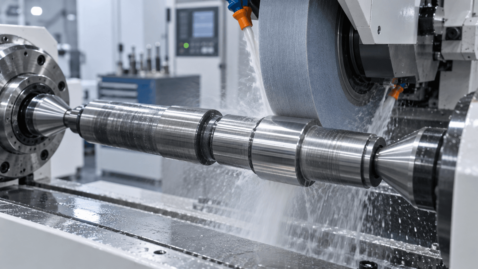
PRECISION GRINDING
Precision turning establishes the route efficiently; grinding can finish bearing seats, shoulders and other functional surfaces after heat treatment where the drawing requires finer diameter, geometry or finish control.
For a taper or internal bore, the important relationship is the interface axis relative to the bearing-defined rotational axis—not simply the nominal taper angle or diameter.
MANUFACTURING ROUTE
Review bearing seats, spindle nose, taper or bore, drive interface and runout references.
Turn the primary OD sections, journals, shoulders and nose with finishing allowance where required.
Produce the specified through bore, drawbar passage, internal taper, threads and other internal features.
Apply the drawing-defined heat treatment while planning for dimensional change and final finishing.
Finish bearing seats, precision shoulders and taper or bore surfaces relative to the required axis.
Inspect runout, journal dimensions, taper alignment, coaxiality, straightness and roughness.
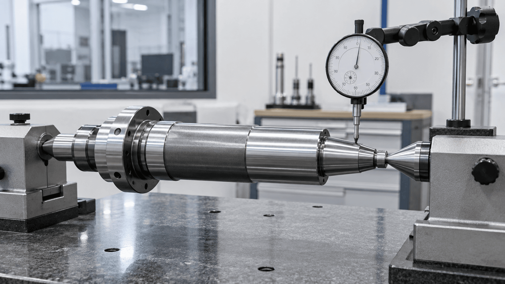
RUNOUT INSPECTION
Spindle inspection focuses on the features that establish bearing alignment and working-end accuracy. A precision test bar or indicator setup can help evaluate the functional relationship of the nose or taper to the axis.
RELATED ROTATING SHAFTS
A motor shaft primarily supports the rotor and transfers motor torque. A spindle shaft is designed around the accuracy and stiffness of the tool, wheel, chuck or workpiece interface under machining load.
Working rotational accuracy, bearing seats, nose/taper geometry, stiffness and runout are the central requirements.
Rotor fit, motor bearing support and reliable torque transmission set the primary engineering focus.
Explore precision motor shafts →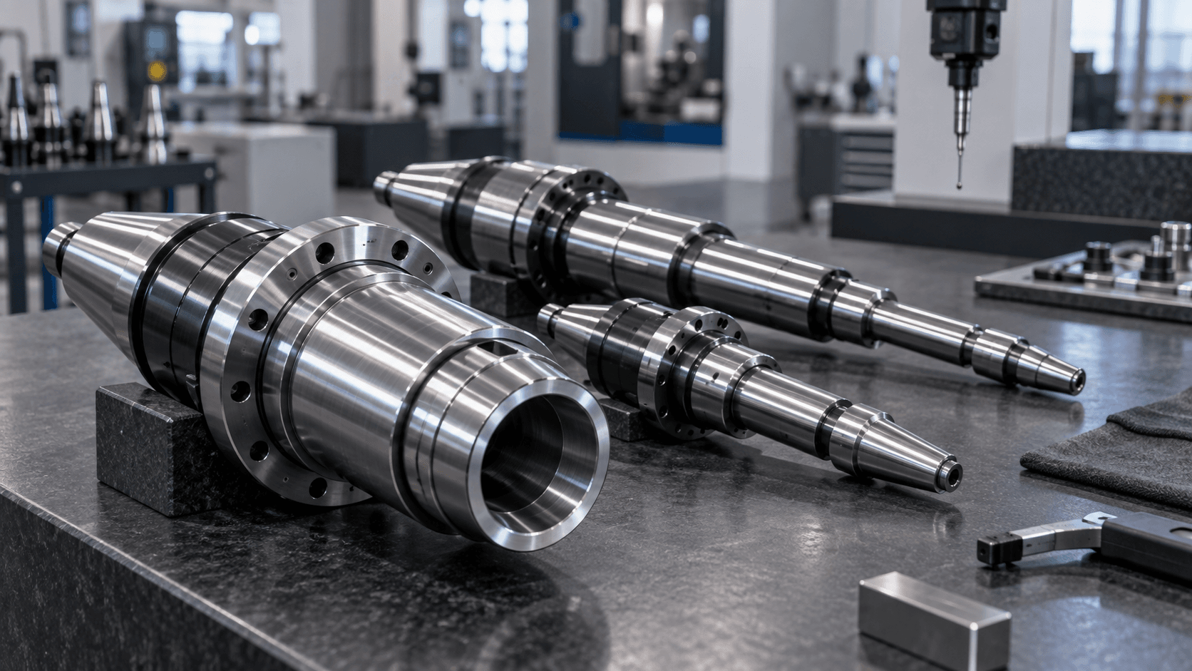
HIGH-SPEED CONSIDERATIONS
As speed increases, balance, bearing fit, shaft stiffness, vibration and thermal expansion become increasingly important. Spindle shaft material and treatment should be evaluated together with RPM, loading, assembly and precision requirements.
Discuss Your Spindle Project →PREPARE YOUR RFQ
BUYER QUESTIONS
A spindle shaft is the precision rotating component inside a spindle system. It supports bearings and provides the working interface for a tool, workpiece, chuck, wheel or other rotating component.
No. The shaft is the rotating component. A full spindle assembly can also include bearings, housing, seals, clamping systems, drive components and sensors.
Grinding can provide the diameter, cylindricity, roundness and finish required by precision bearings, particularly after heat treatment.
Runout is the deviation of a rotating surface from its intended axis. Radial runout acts perpendicular to the axis; axial runout is commonly measured at a face or shoulder.
Yes. A hollow spindle can provide a passage for bar stock, a drawbar, coolant, clamping components or other internal systems.
Send the drawing or CAD model, material, bearing-seat specifications, nose or taper geometry, runout requirements, treatment, maximum RPM and quantity.
READY TO START?